
Related Manuals for Siemens TC65 Terminal


Summary of Contents for Siemens TC65 Terminal
- Page 1 TC65 Terminal Siemens Cellular Engine Version: 02.000b DocID: TC65 Terminal_HD_V02.000b...
- Page 2 GSM products, which also apply to cellular phones must be followed. Siemens or its suppliers shall, regardless of any legal theory upon which the claim is based, not be liable for any consequential, incidental, direct, indirect, punitive or other damages whatsoever...
-
Page 3: Table Of Contents
Terms and Abbreviations ..................9 Regulatory and Type Approval Information ............12 1.3.1 Directives and Standards..............12 1.3.2 Safety Precautions ................15 Key Features of the TC65 Terminal................17 Technical Requirements for Using TC65 Terminal..........20 Interface Description ....................21 Overview ......................21 Block Diagram....................22 Operating Modes ....................23 Terminal Circuit....................24... - Page 4 TC65 Terminal Hardware Interface Description Confidential / Released Characteristics of the Audio Interface ..............55 5.6.1 Audio Parameters Adjustable by AT Commands........56 Characteristics of the GPIOs................57 Characteristics of the Pulse Counter ..............57 Characteristics of the I C interface ..............58 5.10 Characteristics of the SPI interface ..............58 5.11 Characteristics of the ADC Interface ..............59...
- Page 5 TC65 Terminal Hardware Interface Description Confidential / Released Tables Table 1: Directives........................12 Table 2: Standards of North American Type Approval............12 Table 3: Standards of European Type Approval..............13 Table 4: Requirements of quality..................13 Table 5: Standards of the Ministry of Information Industry of the People’s Republic of China .13 Table 6: Toxic or hazardous substances or elements with defined concentration limits ..14...
- Page 6 Figure 13: ADC balanced amplifier..................41 Figure 14: Mechanical dimensions ..................45 Figure 15: Tyco Micro Mate-N-LOK series on the TC65 Terminal ........46 Figure 16: Mating connector Tyco Micro Mate-N-LOK series ..........46 Figure 17: Receptacle contact for Tyco Micro Mate-N-LOK series ........46 Figure 18: Mechanical dimensions of the Tyco Mate_N_LOK connector on the TC65 Terminal.
-
Page 7: Document History
TC65 Terminal Hardware Interface Description Confidential / Released Document History Preceding document: "TC65 Terminal Hardware Interface Description" Version 02.000a New document: "TC65 Terminal Hardware Interface Description" Version 02.000b Chapter What is new 1.3.1 Added MII standards to list of directives and standards (Table 5 and Table 6). -
Page 8: Introduction
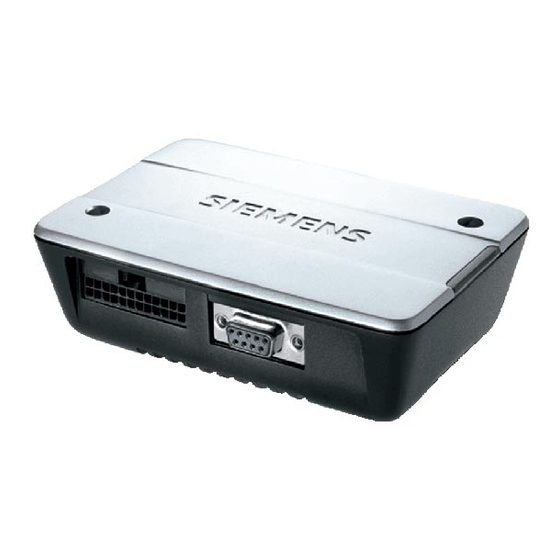
The TC65 Terminal is a compact GSM modem for the transfer of data, voice, SMS and faxes in GSM networks. Industrial standard interfaces and an integrated SIM card reader allow using TC65 Terminal easily as a quad band GSM terminal. -
Page 9: Terms And Abbreviations
Clear to Send Digital-to-Analog Converter dBm0 Digital level, 3.14dBm0 corresponds to full scale, see ITU G.711, A-law Data Communication Equipment (typically modems, e.g. Siemens GSM engine) DCS 1800 Digital Cellular System, also referred to as PCN Digital Signal Processor Data Set Ready... - Page 10 TC65 Terminal Hardware Interface Description Confidential / Released Abbreviation Description High Impedance Half Rate Input/Output IMEI International Mobile Equipment Identity International Standards Organization International Telecommunications Union kbps kbits per second Light Emitting Diode Mbps Mbits per second Man Machine Interface...
- Page 11 TC65 Terminal Hardware Interface Description Confidential / Released Abbreviation Description Terminal Equipment, also referred to as DTE Transmit Direction UART Universal asynchronous receiver-transmitter Unsolicited Result Code USSD Unstructured Supplementary Service Data TC65 Terminal_HD_V02.000b Page 11 of 65 2007-02-19...
-
Page 12: Regulatory And Type Approval Information
Confidential / Released Regulatory and Type Approval Information 1.3.1 Directives and Standards TC65 Terminal is designed to comply with the directives and standards listed below. Table 1: Directives 99/05/EC “Directive of the European Parliament and of the Council of 9 March, 1999 on radio equipment and telecommunications terminal equipment and the mutual recognition of their conformity”, in short referred to as R&TTE Directive 1999/5/EC... -
Page 13: Table 3: Standards Of European Type Approval
TC65 Terminal Hardware Interface Description Confidential / Released Table 3: Standards of European Type Approval 3GPP TS 51.010-1 “Digital cellular telecommunications system (Phase 2); Mobile Station (MS) conformance specification” V5.10.0 ETSI EN 301 511 “V9.0.2 (2003-03) Candidate Harmonized European Standard (Telecommunications series) Global System for Mobile communications (GSM);... -
Page 14: Table 6: Toxic Or Hazardous Substances Or Elements With Defined Concentration Limits
TC65 Terminal Hardware Interface Description Confidential / Released Table 6: Toxic or hazardous substances or elements with defined concentration limits 部件名称 有毒有害物质或元素 Hazardous substances Name of the part 铅 汞 镉 六价铬 多溴联苯 多溴二苯醚 (Pb) (Hg) (Cd) (Cr(VI)) (PBB) (PBDE) 金属部件... -
Page 15: Safety Precautions
Safety Precautions The following safety precautions must be observed during all phases of the operation, usage, service or repair of any cellular terminal or mobile incorporating TC65 Terminal. Manufacturers of the cellular terminal are advised to convey the following safety information to users and operating personnel and incorporate these guidelines into all manuals supplied with the product. - Page 16 TC65 Terminal Hardware Interface Description Confidential / Released IMPORTANT! Cellular terminals or mobiles operate using radio signals and cellular networks. In that case connections cannot be guaranteed at all times under all conditions. Therefore, you should never rely solely upon any wireless device for essential communications, for example emergency calls.
-
Page 17: Key Features Of The Tc65 Terminal
Implementation General Incorporates TC65 The TC65 module handles all processing for audio, signal and module data within the TC65 Terminal. Internal software runs the application interface and the whole GSM protocol stack. Frequency bands Quad band: GSM 850/900/1800/1900MHz GSM class... - Page 18 IP address IP version 6 Remote SIM Access TC65 Terminal supports Remote SIM Access. RSA enables TC65 Terminal to use a remote SIM card via its serial interface and an external application, in addition to the SIM card locally attached to the dedicated lines of the application interface.
- Page 19 TC65 Terminal Hardware Interface Description Confidential / Released Feature Implementation Interfaces • Serial interface 8-wire modem interface with status and control lines, unbalanced, asynchronous • Fixed bit rates: 300 bps to 460,800 bps • Autobauding: 1,200 bps to 460,800 bps •...
-
Page 20: Technical Requirements For Using Tc65 Terminal
TC65 Terminal Hardware Interface Description Confidential / Released Technical Requirements for Using TC65 Terminal • Computer running Windows 2000, Windows XP • 1.8V or 3.0V SIM card • 8 to 30 Volts power supply unit • RS-232 cable (for high data rates ≤ 1.5m) •... -
Page 21: Interface Description
Confidential / Released Interface Description Overview TC65 Terminal provides the following connectors for power supply, interface and antenna: 1. 24-pole GPIO Micro Mate-N-LOK connector for GPIOs, I²C, SPI, ADC 2. 9-pole (female) SUB-D plug for RS-232 serial interface 3. SMA connector (female) for antenna 4. -
Page 22: Block Diagram
TC65 Terminal Hardware Interface Description Confidential / Released Block Diagram Figure 3 shows a block diagram of a sample configuration that incorporates a TC65 Terminal and typical accessories. Module TC65 Contact spring Heat Sink Antenna 80 pin B2B (female) Contact... -
Page 23: Operating Modes
TC65 Terminal Hardware Interface Description Confidential / Released Operating Modes The table below briefly summarizes the various operating modes referred to in the following chapters. Table 7: Overview of operating modes Normal operation GSM / GPRS SLEEP Various power save modes set with AT+CFUN command. -
Page 24: Terminal Circuit
Feeding Bridge Handset AGND SIM-Holder CCxx RS232 9 pole level D-Sub (female) converter ASC0 RS232 VPOS VNEG BATT+ lin. Reg- 2.9V PWR_IND SYNC blue (female) RF-Cable Figure 4: TC65 Terminal circuit block diagram TC65 Terminal_HD_V02.000b Page 24 of 65 2007-02-19... -
Page 25: Power Supply
Confidential / Released Power Supply The power supply of the TC65 Terminal has to be a single voltage source of POWER=8V…30V capable of providing a peak during an active transmission. The uplink burst causes strong ripples (drop) on the power lines. -
Page 26: Switch On Tc65 Terminal
Switch on via IGT_IN line (power supply connector) or DTR line (serial connector). The rising edge of the IGT_IN line or the DTR line voltage generates an ignition signal (impulse) so that it is possible to switch on the TC65 Terminal from the host or by remote control. -
Page 27: Signal States After Startup
TC65 Terminal Hardware Interface Description Confidential / Released 3.5.5 Signal States after Startup Table 9 describes the various states each interface pin passes through after startup and during operation. The state of several pins will change again once the respective interface is activated or configured by AT command. -
Page 28: Rs-232 Interface
Confidential / Released RS-232 Interface The serial interface of the TC65 Terminal is intended for the communication between the GSM module and the host application. This RS-232 interface is a data and control interface for transmitting data, AT commands and providing multiplexed channels. EMC immunity complies with the vehicular environment requirements according to EN 301 489-7. - Page 29 DSR0 DCD0 RING0 RING TC65 Terminal is designed for use as a DCE. Based on the conventions for DCE-DTE connections it communicates with the customer application (DTE) using the following signals: • Port TxD @ application sends data to TXD of TC65 Terminal •...
-
Page 30: Audio Interface
TC65 Terminal Hardware Interface Description Confidential / Released Audio Interface The audio interface provides one analog input for a microphone and one analog output for an earpiece. • The microphone input and the earpiece output are balanced. • For electret microphones a supply source is implemented. -
Page 31: Supported Audio Modes
1. The settings are optimized for the reference handset (type Votronic) connected to the TC65 Terminal (see chapters 6.1 and 7). To ensure that the reference parameters are always within the limits demanded by the standards they cannot be changed by AT command. -
Page 32: Speech Processing
TC65 Terminal Hardware Interface Description Confidential / Released 3.7.2 Speech Processing The speech samples from the ADC are handled by the DSP of the baseband controller to calculate e.g. amplifications, sidetone, echo cancellation or noise suppression depending on the configuration of the active audio mode. These processed samples are passed to the speech encoder. -
Page 33: Antenna Interface
SIM card during operation. Also, no guarantee can be given for properly initializing any SIM card that the user inserts after having removed a SIM card during operation. In this case the TC65 Terminal must be restarted by the application. -
Page 34: Table 12: Pin Assignment - Sim Card Holder
TC65 Terminal Hardware Interface Description Confidential / Released Table 12: Pin assignment – SIM card holder Pin number on Signal name Function holder VSIM Supply voltage for SIM card is generated by the module. CCRST Chip card reset, prompted by the module... -
Page 35: Io Interface
• Backup supply • VDD supply • On/Off switch of the TC65 Terminal • Pulse counter The total cable length of the digital lines for I²C and SPI interfaces should not exceed 150mm. Figure 10: IO interface connector front view TC65 Terminal_HD_V02.000b... -
Page 36: Table 13: Assignment Of The Io Interface Connector
TC65 Terminal Hardware Interface Description Confidential / Released Table 13: Assignment of the IO interface connector Signal name Description I2CCLK_SPICLK I2C or SPI Clock I2CDAT_SPIDO I2C Data or SPI Data out GPIO3 Programmable GPIO GPIO4 Programmable GPIO GPIO5 Programmable GPIO... -
Page 37: Gpios
3.10.1 GPIOs The TC65 Terminal provides 10 GPIO pins at the IO interface connector. Each GPIO line is ESD protected and a serial resistor of 100 Ohm is added. This avoids short circuits and is especially important in the first stages of development where the Java application is not yet fully implemented. -
Page 38: Using Gpio Pin10 As Pulse Counter
These are the serial data line I2CDAT and the serial clock line I2CCLK. The TC65 Terminal acts as a single master device, e.g. the clock I2CCLK is driven by the Terminal. The connection I2CDAT is a bi-directional line. -
Page 39: Spi Interface
The TC65 Terminal acts as a single master device, e.g. the clock SPICLK is driven by the TC65 Terminal. Whenever the SPICS pin is in a low state, the SPI bus is activated and data can be transferred from the Terminal and vice versa. The SPI interface uses two independent lines for data input (SPIDI) and data output (SPIDO). -
Page 40: Figure 12: Characteristics Of Spi Modes
TC65 Terminal Hardware Interface Description Confidential / Released Clock phase SPI MODE 0 SPI MODE 1 SPICS SPICS SPICLK SPICLK SPIDO SPIDO SPIDI SPIDI Sample Sample SPI MODE 2 SPI MODE 3 SPICS SPICS SPICLK SPICLK SPIDO SPIDO SPIDI SPIDI... -
Page 41: Analog-To Digital Converter (Adc)
Note: It is necessary to recalculate measurement results because an amplifier is used to scale down the ADCx_IN input voltage of the TC65 Terminal (5V) to the ADCx_IN input voltage of the in-built TC65 module (2.4V). Two parameters (determined and stored by factory) have to be used for offset compensation... -
Page 42: Rtc Backup Supply
The two pins of the power supply at the IO interface connector are directly connected to two pins of the Western Jack for power supply. This allows supplying the TC65 Terminal by using the Power connector or via the IO interface connector. -
Page 43: Status Led
TC65 Terminal Hardware Interface Description Confidential / Released 3.11 Status LED A blue LED displays the operating status of the TC65 Terminal. The LED can be operated in two different display modes: AT^SSYNC=1 or AT^SSYNC=2 (factory default). For more information of the different operating states and changing this mode please refer to [1]. -
Page 44: Mechanical Characteristics
130mm x 90mm x 38mm Temperature range -30°C to +65°C ambient temperature Protection class IP40 (Avoid exposing TC65 Terminal to liquid or moisture, for example do not use it in a shower or bath.) Mechanical vibrations Amplitude 7.5mm at 5-200Hz sinus Max. pulse acceleration... -
Page 45: Figure 14: Mechanical Dimensions
TC65 Terminal Hardware Interface Description Confidential / Released Figure 14: Mechanical dimensions TC65 Terminal_HD_V02.000b Page 45 of 65 2007-02-19... -
Page 46: Io Interface Connector
I2C, SPI and GPIO interfaces of the Terminal. The type of the receptacle assembled on the TC65 Terminal is Micro Mate-N-LOK 3mm from Tyco Electronics. Mating headers can be chosen from the Tyco Micro Mate-N-LOK Series. For latest product information please contact your Micro Electronics dealer or visit the Tyco home page, for example http://www.tycoelectronics.com. -
Page 47: Recommended Mating Connector
Number of Positions 40.00 36.86 33.00 Values in mm Figure 18: Mechanical dimensions of the Tyco Mate_N_LOK connector on the TC65 Terminal. 4.1.1 Recommended Mating Connector Table 20: Ordering information for mating connector Tyco Micro Mate-N-LOK Item Number of positions... -
Page 48: Electrical And Environmental Characteristics
TC65 Terminal Hardware Interface Description Confidential / Released Electrical and Environmental Characteristics Table 21: Absolute maximum ratings Parameter Port / Description Min. Max. Unit Supply voltage POWER Input voltage for Ignition IGT_IN Input voltage for EMERGOFF emergency off RS-232 input voltage... -
Page 49: Table 22: Operating Conditions
GPRS-Class (e.g. from GPRS Class 12 to GPRS Class 8). At a successful change of the GPRS class the intrinsic heating of the TC65 Terminal will be reduced. If the board temperature decreases by an amount of 15°C the GPRS Class will be stepped up again. -
Page 50: Table 24: Longest Duration Until 81°C Are Reached
TC65 Terminal Hardware Interface Description Confidential / Released The following table shows the longest possible duration of a connection until 81°C (Temperature of GPRS Class Change) are reached at the NTC when the ambient temperature is 65°C. Table 24: Longest duration until 81°C are reached... -
Page 51: Characteristics Of The Power Supply
TC65 Terminal Hardware Interface Description Confidential / Released Characteristics of the Power Supply Table 26: Characteristics of the power supply Parameter Description Conditions Max Unit Operating Voltage for one minute POWER 0.45 Power Down mode @12V 0.50 @30V 0.80 SLEEP mode... -
Page 52: Characteristics Of On/Off Control
TC65 Terminal Hardware Interface Description Confidential / Released Characteristics of On/Off control Table 27: Characteristics On/Off control Function Signal name Signal form and level Comment Emergency EMERGOFF Emergency-off switches ≈ 100kOhm the power supply of the Terminal off. max = 0.8V min = -0.3V... -
Page 53: Characteristics Of The Rs-232 Interface
TC65 Terminal Hardware Interface Description Confidential / Released Characteristics of the RS-232 interface Table 28: Characteristics of the RS-232 interface Function Signal name Signal from and level Comment RS232 min = 3kOhm max = 0.6V min = 2.4V max = ±25V If lines are unused keep pin open. -
Page 54: Characteristics Of The Sim Interface For Use With 1.8V Cards
TC65 Terminal Hardware Interface Description Confidential / Released Characteristics of the SIM interface for Use with 1.8V Cards Table 30: Characteristics of the SIM interface for use with 1.8V cards Function Signal name Signal form and level Comment Reset CCRST ≈... -
Page 55: Characteristics Of The Audio Interface
TC65 Terminal Hardware Interface Description Confidential / Released Characteristics of the Audio Interface Table 31: Characteristics of the audio interface Function Signal name Parameter Min. Typ. Max. Unit DC (no load) at MICP DC at MICP in POWER DOWN DC (no load) at MICN... -
Page 56: Audio Parameters Adjustable By At Commands
TC65 Terminal Hardware Interface Description Confidential / Released 5.6.1 Audio Parameters Adjustable by AT Commands Table 32: Audio Parameters Adjustable by AT Commands Parameter Influence to Range Gain range Calculation inBbcGain MICP/MICN analog amplifier gain 0...7 0...42dB 6dB steps of baseband controller before ADC... -
Page 57: Characteristics Of The Gpios
TC65 Terminal Hardware Interface Description Confidential / Released Characteristics of the GPIOs Table 33: Characteristics of the GPIOs Function Signal name Signal form and level Comment GPIO1 GPIO2 ≈ 100Ω If unused keep pins with a max = 0.4V at I = 2mA... -
Page 58: Characteristics Of The I 2 C Interface
TC65 Terminal Hardware Interface Description Confidential / Released Characteristics of the I C interface Table 35: Characteristics of the I C interface Function Signal name Signal form and level Comment I2CDAT is configured as ≈ 33Ω Open Drain and needs a max = 0.25V at I = 2mA... -
Page 59: Characteristics Of The Adc Interface
TC65 Terminal Hardware Interface Description Confidential / Released 5.11 Characteristics of the ADC Interface Table 37: Characteristics of the ADC interface Function Signal name Signal form and level Comment gle ended or differential input voltage ADCx_IN_N = GND or negative... -
Page 60: Rf Connector
TC65 Terminal Hardware Interface Description Confidential / Released 5.13 RF Connector Table 39: RF connector Parameter Conditions Min. Typical Max. Unit GPRS connectivity GPRS multislot class 12 Time slots Rx Time slots Tx GPRS coding schemes Full implementation CS-1,CS-2,CS-3, CS-4... -
Page 61: Full Type Approval
TC65 Terminal Hardware Interface Description Confidential / Released Full Type Approval Siemens Reference Setup The Siemens reference setup submitted to type approve TC65 Terminal consists of the following components: • TC65 Terminal with approved GSM module TC65 • Votronic Handset type •... -
Page 62: Compliance With Fcc Rules And Regulations
Please note that changes or modifications not expressly approved by the party responsible for compliance could void the user’s authority to operate the equipment. Cable Requirements The TC65 Terminal has to be tested and approved for use with a maximum cable length of 3m for following interfaces: - USB interface (shielded) -
Page 63: Restrictions
>30% for >1ms does reset or shut down the terminal. The TC65 Terminal does not resist against test pulse 5 according ISO 7637-2 (load dump at vehicles 24 volt supply voltage). The internal slow acting, not removable fuse will be damaged. -
Page 64: List Of Parts And Recommended Accessories
TC65 Terminal Hardware Interface Description Confidential / Released List of Parts and Recommended Accessories Table 40: List of parts and accessories Description Supplier Ordering information TC65 Terminal Siemens Siemens ordering number: L36880-N8670-B200 Power supply unit Sphere Design Ordering number: 39020... - Page 65 TC65 Terminal Hardware Interface Description Confidential / Released Description Supplier Ordering information GPIO-Connector Tyco Electronics Ordering Numbers: Mating connector Micro Mate-N_LOK 3mm: 2-794617-4 Crimp Snap_In contacts: 794606-* or 794607-* (24 pieces/housing for full assembly) Hand Tool CERTI-CRIMP II Straight: 91501-1 http://www.tycoelectronics.com/cust.stm...