
Related Manuals for Siemens AOP


Summary of Contents for Siemens AOP
-
Page 1: Table Of Contents
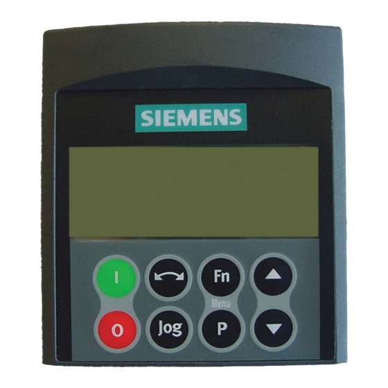
Issue 07/05 Contents Warnings and Notes 1.1 Special Key Functions Applications Examples 2.1 Single drive control using the AOP 2.2 Network Setup (RS 485 With Panel Mounting Kit) 2.3 Parameter Upread 2.4 Parameter Download 2.5 AOP Parameters 2.6 Slave Mode and operation with DriveMonitor 2.7 MM3 Upread... - Page 2 AOP Menu Structure The diagram below gives an overview of the menu structure of the AOP. Introduction The Advanced Operator Panel (AOP) has been designed to enhance the interface and communications capability of the MICROMASTER 4th generation frequency inverters. For details on the operation of the AOP see the following Sections:...
-
Page 3: Warnings And Notes
The AOP will not START or STOP an attached inverter until it has been set as the command source. (P0700 = 4 or 5) If the AOP has been set as the I/O control (P0700= 4 or 5); to prevent unexpected drive operation, the USS timeout parameter (P2014) should be set to 5000. -
Page 4: Special Key Functions
Is used throughout the manual to indicate a keypad special function. Applications Examples Single drive control using the AOP To configure a single inverter with the AOP as the control source, the following procedure should be performed to change the required parameters. Fit the AOP to the inverter. -
Page 5: Network Setup (Rs 485 With Panel Mounting Kit)
Micromaster 4 generation drive. These modes are both under the Master mode of operation on the AOP allowing a single drive to be accessed on the network with full control/parameter access or selecting B or broadcast mode all drives on the network can be set to start/stop at the same time. - Page 6 Note If the AOP is to be used as the normal control means for the inverter it is recommended that the user Set P2014.0 = 5000. To do this first set P0003 = 3. This setting will cause the drive to trip if communication with the control source, the AOP, is lost.
-
Page 7: Parameter Upread
2.2.3 Network control – PC Mode The AOP may be configured as an RS232 to RS485 converter. This will allow a PC running software such as DriveMonitor to connect to a network of drives, as described above. - Page 8 To upread a parameter set from an inverter to the AOP the following procedure must be performed: From the Main Menu scroll through the list of options using the keys until ‘UPREAD’ is highlighted. Press the key to confirm the selected option.
-
Page 9: Parameter Download
In Master mode the user would have to select a specific inverter from the networked inverters. Using the keys scroll through the parameter sets of the AOP, from which the information is to be written. The user will be presented with a confirmation screen. Press the key to confirm or to cancel the process. -
Page 10: Aop Parameters
Select ‘Parameters’ as described in Section 6 on page 22. Select the AOP Parameter Set. View ‘All’ parameters. Set P0003 = 3. The AOP internal parameters that display useful information are as follows: P0964 Software Version Information P8552 Base slave address... -
Page 11: Mm3 Upread
MM3 Upread It is possible to use the AOP to upread a parameter set held on an MM3 inverter. To do this the user must use a PMK as an RS232 to RS485 converter to allow the AOP to communicate with the MM3. - Page 12 If necessary use the keys to select ON. Press to confirm the selection and move the cursor to the Day of the Week field. Using the keys select to required Day of the Week. AOP Operating Instructions – Issue 07/05 6SE6400-5AP00-0BB0...
- Page 13 Event View field. Note If no events are programmed into the AOP, the cursor will still move to this field. Press to move the cursor to the Inverter Address field.
- Page 14 To EXIT from the TIMER screen and save the changes, two long presses of the are required. To CANCEL/DELETE an event, press the keys simultaneously. AOP Operating Instructions – Issue 07/05 6SE6400-5AP00-0BB0...
-
Page 15: Aop Start-Up
Normal operation display (start help is OFF). Display type depends on the operating mode in use. Language Selection The AOP has the ability to display information in a number of languages. Notes Prior to language selection the AOP has no control over the inverter. -
Page 16: Start Help
The user then selects OPERATE The screen now displays the current state of the inverter and motor. An explanation of the information displayed on the screen is given in the following table: AOP Operating Instructions – Issue 07/05 6SE6400-5AP00-0BB0... -
Page 17: Main Menu (Local Mode)
Inverter is in a running state with pulses enabled. STOPPED Inverter stopped – pulses disabled. Inverter will not run; a fault as described by the AOP under FAULT Diagnostics is preventing operation. Inverter has detected a problem in normal operation and is WARNING informing the user of the condition of the inverter. -
Page 18: Wait Request
Allows the user to read a parameter set from the inverter UPREAD into the AOP. DOWNLOAD Allows the user to write a parameter set to the inverter. Allows the user to select a new language for the AOP LANGUAGE display. Allows the user to personalize the configuration of the SETUP AOP. -
Page 19: Operate Menu
Main Menu. 4.1.2 Display Drive State The AOP has the ability to monitor the state of the inverter and motor to which it is connected. The current activity of the inverter and motor will be displayed, including any fault conditions. -
Page 20: Operating In Master Mode
4.1.3 Drive Type Check The AOP will check the type of inverter to which is connected. If the drive type is incompatible with the AOP, it will refuse to function and return the user to the Main Menu. Operating in Master Mode Selecting ‘Operate’... -
Page 21: Selecting The Operating Mode
A summary of the various modes and their limitations is contained in the table below. When changing the mode of the AOP, the user is always presented with a confirmation screen. Press to confirm the selected mode. -
Page 22: Local Mode
AOP on initial power-up or after a reset has been performed. Master Mode In Master mode the AOP can control up to 31 inverters connected in a multi- drop arrangement. Full operator control of each inverter is possible with access to all normal inverter and AOP internal parameters. - Page 23 The parameter value that has been changed will be retained within the AOPs internal memory, but not sent to the inverter. Should power to the inverter or AOP be disconnected, all changes will be lost.
-
Page 24: Use Of Function Key
A number of parameters contain indexes that group together closely related parameter type information. The access level set on the inverter and not the AOP governs all access to the various levels of parameter sets. AOP Operating Instructions – Issue 07/05... -
Page 25: Aop Stored Parameter Sets
To edit another parameter steps 4 to 10 should be repeated until all the necessary parameters have been configured. AOP Stored Parameter Sets The AOP contains a battery-backed storage facility capable of storing up to 10 parameter sets. The standard AOP will be issued with three drive type parameter sets:... -
Page 26: Engineering
The user is then presented with the Internal mode menu screen. Using the keys highlight ‘PARAMETERS’. The user is then presented with the internal edit menu for the AOP. Using the keys highlight required parameter set number. - Page 27 7.1.1 Backlighting To activate the backlighting option on the AOP, the following procedure should performed: Using the keys select the ‘Backlighting’ option from the Setup menu.
- Page 28 7.1.4 Cursor Type To change the type of cursor that the AOP uses, select the ‘Cursor Type’ option from the Setup Menu. Using the keys scroll through the cursor types until the required cursor is highlighted.
- Page 29 Setup menu. Pressing the keys simultaneously, at any time will display the relevant help screens to assist the user. AOP Operating Instructions – Issue 07/05 6SE6400-5AP00-0BB0...
- Page 30 Warning This function deletes all parameter sets and settings stored within the The AOP reset is accomplished by selecting the ‘AOP Reset’ option from the Setup menu. The normal default for this function is to clear all internal faults, message logs and the stored parameter sets.
- Page 31 The user is then presented with the parameter reset screen: Press to confirm the AOP reset and the deletion of the inverter parameter sets stored within the AOP’s memory. Press to perform the AOP reset without deleting the inverter parameter sets stored within the AOP’s memory.
-
Page 32: Fault Indication
This is dependent on the fault condition and the cause of the fault should be investigated. To be able to clear the fault the AOP must have been set as the command source (P0700 =4 or 5) -
Page 33: Multiple Faults
For instructions on how to acknowledge the fault messages, see Section 9.1. Inverter Fault Codes When a fault occurs on the inverter(s) to which the AOP is connected, a fault code is displayed with a description of the relevant fault. - Page 34 Press the keys simultaneously to display the help screen which will contain details of the relevant corrective action. Press and hold down the key to return to the Main Menu. AOP Operating Instructions – Issue 07/05 6SE6400-5AP00-0BB0...
- Page 35 NOTES AOP Operating Instructions – Issue 07/05 6SE6400-5AP00-0BB0...
-
Page 36: 6Se6400-5Ap00-0Bb0
For use in a pollution degree 2 environment ISO 9001 Siemens plc operates a quality management system, which complies with the requirements of ISO 9001. To submit any suggestions for improvements, please visit the Siemens Standard Drives Web Site at http://www.siemens.de/micromaster *6SE6400-5AP00-0BB0* Siemens plc Automation &...