Advertisement
Quick Links
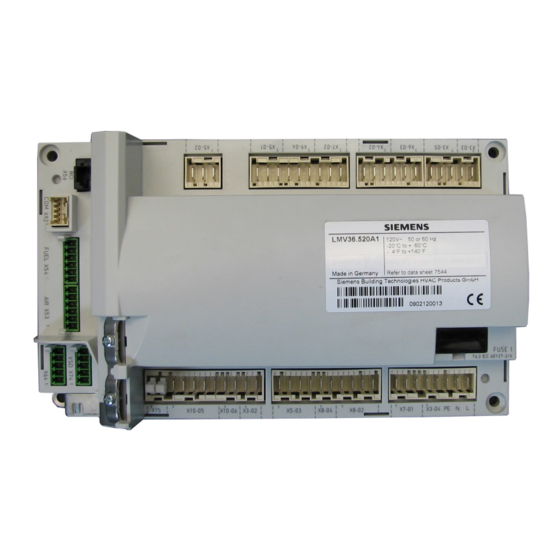
Basic unit with integrated fuel-air
ratio control for forced draft burners
Switch unit for switching the valve
control or feedback signals of both
fuels
CC1N7544en
21.05.2021
LMV36.520...
The LMV36 burner management system is a microprocessor-based burner
control with matching system components for control and supervision of forced
draft burners of medium to high capacity.
For the use of dual fuel application with 2 fuel actuators, the AGM60 dual fuel
switch unit is required.
The LMV36 / AGM60 and this Data Sheet are intended for use by OEMs which
integrate the actuators in their products!
7
544
AGM60.4A9
LMV36.520...
AGM60.4A9
Smart Infrastructure
Advertisement

Related Manuals for Siemens LMV36.520 Series


Summary of Contents for Siemens LMV36.520 Series
- Page 1 LMV36.520... AGM60.4A9 Basic unit with integrated fuel-air LMV36.520… ratio control for forced draft burners Switch unit for switching the valve AGM60.4A9 control or feedback signals of both fuels The LMV36 burner management system is a microprocessor-based burner control with matching system components for control and supervision of forced draft burners of medium to high capacity.
- Page 2 Microprocessor-controlled LMV36 for single-fuel burners of any capacity, with electronic fuel-air ratio control, with up to 2 actuators, and with integrated gas valve proving. The system components (AZL2 and actuators) are connected directly to the LMV36 in single-fuel operation. All safety-related digital inputs and outputs of the LMV36 are supervised by a contact feedback network.
- Page 3 The electrical connections of the LMV36 and the AGM60 comply with the requirements of EN 60335-2-102. EAC Conformity mark (Eurasian Conformity mark) ISO 9001:2015 ISO 14001:2015 OHSAS 18001:2007 China RoHS Hazardous substances table: http://www.siemens.com/download?A6V10883536 3/30 Smart Infrastructure CC1N7544en 21.05.2021...
-
Page 4: Supplementary Documentation
Life cycle LMV36 The burner management system has a designed lifetime* of 250,000 burner startup cycles which, under normal operating conditions in heating mode, correspond to approx. 10 years of usage (starting from the production date given on the type field). AGM60 The AGM60 dual fuel switch unit has a designed lifetime* of 5,000 burner startup cycles which, under normal operating conditions in heating mode, correspond to approx. - Page 5 System overview The diagram shows the full scope of functions of the LMV36. The actual functions are to be determined based on the respective execution / configuration! 5/30 Smart Infrastructure CC1N7544en 21.05.2021...
- Page 6 Ordering Burner control LMV36 The basic unit is the actual burner control featuring all-polar input/output terminals. No operating elements. Operation via detached ancillary units for wire-bound communication. See Basic Documentation P7544. Article no. Type Mains voltage Parameter set Detectors BPZ:LMV36.520A1 LMV36.520A1 AC 120 V North America...
- Page 7 Ordering (cont'd) Display and operating AZL21.00A9 units Article no.: BPZ:AZL21.00A9 Detached display and operating unit, choice of mounting methods, 8-digit LCD, 5 buttons, BCI for LMV36, degree of protection IP40. See Data Sheet N7542. AZL23.00A9 Article no.: BPZ:AZL23.00A9 Detached display and operating unit, choice of mounting methods, 8-digit LCD, 5 buttons, BCI for LMV36 system, degree of protection IP54.
- Page 8 Ordering (cont´d) Flame detectors QRA2 Flame detector for use with Siemens burner controls, for the supervision of gas flames and yellow- or blue-burning oil flames as well as ignition spark checking. Plastic housing, metalized to prevent static charging caused by the air flow from the fan.
- Page 9 Ordering (cont´d) Actuators SQM33.4 Rated torque 1.2 Nm (0.8 Nm holding torque when dead), running time 5 s, stepper motor, front mounting, D-type drive shaft. See Data Sheet N7813. SQM33.5 Rated torque 3 Nm (2.6 Nm holding torque when dead), running time 5 s, stepper motor, front mounting, D-type drive shaft.
- Page 10 Ordering (cont´d) Connector sets AGG3.131 Article no.: BPZ:AGG3.131 Complete connector set RAST2.5 / RAST3.5 / RAST5 for Example: X5-02 gas / oil applications, single pack. See Object List C7541 (74 319 0637 0). AGG3.132 Article no.: BPZ:AGG3.132 Complete connector set RAST2.5 / RAST3.5 / RAST5 for gas- / oil applications, pack of 10.
- Page 11 Ordering (cont´d) Example: X5-02 AGG3.162 Article no.: BPZ:AGG3.162 Connector set for AGM60.4A9 (US), RAST5, set of 10 AGM60.4A9. AGG3.162 Connector Terminal Description type RAST5 X5-01 Fuel 1: Pressure switch-min (Pmin) RAST5 X5-02 Fuel 1: Pressure switch-max (Pmax) or POC RAST5 X6-02 Fuel 1: Safety valve (SV) / Magnetic clutch RAST5...
- Page 12 Ordering (cont´d) AGG9 Example X5-03 Single connectors Packing unit 200 in total. Type of Article no. Type Terminal Description connector BPZ:AGG9.203 AGG9.203 RAST5 X3-02 Air pressure switch (LP) BPZ:AGG9.204 AGG9.204 RAST5 X3-03 Burner flange Reset BPZ:AGG9.206 AGG9.206 RAST5 X8-04 ...
- Page 13 Ordering (cont´d) Accessories AGG5.310 Article no.: BPZ:AGG5.310 Accessories set speed control, for burner management systems, composed of sensor disk 50, sensor and mounting set. See Mounting instructions M7550.1 (74 319 9322 0). Cables AGV50.100 Article no.: BPZ:AGV50.100 Signal cable for AZL2, with RJ11 connector, length 1 m, pack of 10.
- Page 14 Ordering (cont´d) Proportional controlling element with mounting plate Proportional controlling element for mounting between threaded flanges in gas trains. Refer to Data Sheet N7646 ASK33.1 Article no.: BPZ:ASK33.1 Larger mounting plate required to replace existing mounting plate. Required for mounting the actuators SQM4 or SQM33.
- Page 15 Connection and internal diagram LMV36 Fuel 1 (oil) Fuel 0 (gas) LMV36... AGM60... X8-02.1 Fuel valve V1 X8-02.1 X32-01.2 X24-04.4 X8-03.1 Fuel valve V1 / V2 X7-01.3 X32-01.3 X24-04.3 Extra valve (SV) X6-02.3 Magnetic clutch Extra valve SV / magnetic clutch X6-03.3 X32-01.5 X24-06.3...
- Page 16 Connection and internal diagram LMV36 (cont´d) Shielding: For shielding the cables on the VSD, refer to: Siemens SED2 VSD Commissioning Manual (G5192), chapter 4 and chapter 7, or Danfoss Operation Manual VLT 6000 (MG60A703), chapter Installation Switching between 2 ratio control curves LMV...
- Page 17 Technical Data Basic unit LMV36 General Mains voltage AC 120 V -15% / +10% Mains frequency 50 / 60 Hz ±6% Power consumption <30 W (typically) Safety class I with parts according to II and III to EN 60730-1:2016 Degree of protection IP00 to EN 60529:1991 + A1:2000 + A2:2013 Note...
- Page 18 Technical Data (cont´d) Terminal loading Total contact loading: «Outputs» Rated voltage AC 120 V, 50 / 60 Hz Unit input current (safety loop) from: Max. 5 A - Fan motor contactor - Ignition transformer - Fuel valves - Oil pump / magnetic clutch (optional via AGM60) Individual contact loading: Fan motor contactor...
- Page 19 Technical Data (cont´d) Cable lengths Mains line AC 120 V Max. 100 m (100 pF/m) Display, BCI For installation under the burner hood or in the control panel Max. 3 m (100 pF/m) Load controller X5-03 Max. 20 m (100 pF/m) Load controller analog X64 (24 mA) Max.
-
Page 20: Environmental Conditions
Technical Data (cont´d) Environmental Storage EN 60721-3-1:1997 conditions Climatic conditions Class 1K3 Mechanical conditions Class 1M2 Temperature range -20...+60 °C Humidity <95 % r.h. Transport EN 60721-3-2:1997 Climatic conditions Class 2K2 Mechanical conditions Class 2M2 Temperature range -30...+60 °C Humidity <95 % r.h. - Page 21 Technical Data (cont´d) Flame supervision with No-load voltage at ION terminal Approx. U Mains ionization probe (X10–05 pin 2) Caution! The ionization probe must be protected against electric shock hazard (electric shock hazard)! Short-circuit current Max. AC 1 mA Required detector current Min.
- Page 22 Technical Data (cont´d) Ionization input Ionization current in µA Measuring circuit for Ionization probe detector current measurement Legend LMV... Electrolytic capacitor 100...470 µF; DC 10...25 V Ionization probe X10-05/2 Microammeter Ri max. 5000 X10-05/1 22/30 Smart Infrastructure CC1N7544en 21.05.2021...
- Page 23 Technical Data (cont´d) Flame supervision with Warning! QRA2 / QRA4 / QRA10 If UV flame detectors QRA2 / QRA4 / QRA10 are used for flame supervision with the LMV36, it must be ensured that the LMV36 is permanently connected to power (conforming to DIN EN 298), thus enabling the LMV36 to detect flame detector failures during startup and shutdown.
- Page 24 Technical Data (cont´d) Flame supervision with No-load voltage at QRB1/QRB3 terminal Approx. DC 5 V QRB1/QRB3 (X10-05 pin 3) Max. perm. length of QRB1/QRB3 3 m (wire – wire 100 pF/m) detector cable (laid separately) Note A detector resistance of RF <500 is identified as a short-circuit and leads to safety shutdown in operation as if the flame had been lost.
- Page 25 Technical Data (cont´d) Flame supervision with Open-circuit voltage at terminal QRB4 Approx. 5 V DC QRB4 (X10-05 pin 3) Permissible length of QRB4 detector 3 m (wire to wire 100 pF/m) cable (laid separately) Threshold values when flame is supervised by QRB4 Start prevention (extraneous light) Flame intensity (parameter 954) ≥10% Operation...
- Page 26 Technical Data (cont´d) Mains voltage AC 120 V -15% / +10% Dual fuel switch unit Mains frequency 50/60 Hz ±6% AGM60 Power consumption <5 W (typically) (without actuator supply) Safety class I with parts according to II and III to EN 60730-1:2016 Galvanic separation between mains voltage terminals and actuator signal lines...
- Page 27 Technical Data (cont´d) Terminal output Outputs Total contact output: Rated voltage AC 120 V, 50/60 Hz Refer also Total contact output in chapter Terminal output Outputs Individual contact loads: Fuel valve Rated voltage AC 120 V, 50/60 Hz ...
- Page 28 Technical Data (cont´d) Environmental conditions Storage EN 60721-3-1:1997 Climatic conditions Class 1K3 Mechanical conditions Class 1M2 Temperature range -20...+60 °C Humidity <95% r.h. Transport EN 60721-3-2:1997 Climatic conditions Class 2K2 Mechanical conditions Class 2M2 Temperature range -30...+60 °C Humidity <95% r.h. Operation EN 60721-3-3:1995 + A2:1997 Climatic conditions...
- Page 29 Dimensions Dimensions in mm LMV36 82,5 22,8 17,3 10,2 12,5 23,5 27,2 82,5 128,5 29/30 Smart Infrastructure CC1N7544en 21.05.2021...
- Page 30 Dimensions (cont´d) Dimensions in mm AGM60 37,9 180,7 2021 Siemens AG Smart Infrastructure, Berliner Ring 23, D-76437 Rastatt Subject to change! 30/30 Smart Infrastructure CC1N7544en 21.05.2021...