
Related Manuals for Siemens RUGGEDCOM RS401


Summary of Contents for Siemens RUGGEDCOM RS401
- Page 1 Preface Introduction Installing the Device RUGGEDCOM RS401 Communication Ports Technical Specifications Dimension Drawings Installation Guide Certification 09/2016 RC1017-EN-05...
-
Page 2: Security Information
Warranty Siemens warrants this product for a period of five (5) years from the date of purchase, conditional upon the return to factory for maintenance during the warranty term. This product contains no user-serviceable parts. Attempted service by unauthorized personnel shall render all warranties null and void. - Page 3 RUGGEDCOM RS401 Installation Guide Contacting Siemens Address Telephone E-mail Siemens Canada Ltd Toll-free: 1 888 264 0006 ruggedcom.info.i-ia@siemens.com Industry Sector Tel: +1 905 856 5288 300 Applewood Crescent Fax: +1 905 856 1995 Concord, Ontario www.siemens.com/ruggedcom Canada, L4K 5C7...
- Page 4 RUGGEDCOM RS401 Installation Guide...
-
Page 5: Table Of Contents
RUGGEDCOM RS401 Installation Guide Table of Contents Table of Contents Preface ......................Alerts ..............................vii Related Documents ..........................vii Accessing Documentation ........................viii Training ............................viii Customer Support ..........................viii Chapter 1 Introduction ..................... 1.1 Feature Highlights ........................1 1.2 Description ........................... 2 Chapter 2 Installing the Device .................. - Page 6 RUGGEDCOM RS401 Table of Contents Installation Guide 3.4.5 Connecting Multiple RS485 Devices ................... 19 Chapter 4 Technical Specifications .................. 4.1 Power Supply Specifications ......................21 4.2 Failsafe Alarm Relay Specifications ....................21 4.3 Copper Ethernet Port Specifications ....................22 4.4 Fiber Optic Ethernet Port Specifications ..................22 4.4.1 10BaseFL Ethernet Optical Specifications ................
-
Page 7: Preface
Installation Guide Preface Preface This guide describes the RUGGEDCOM RS401. It describes the major features of the device, installation, commissioning and important technical specifications. It is intended for use by network technical support personnel who are responsible for the installation, commissioning and maintenance of the device. -
Page 8: Accessing Documentation
Siemens Sales representative. Customer Support Customer support is available 24 hours, 7 days a week for all Siemens customers. For technical support or general information, contact Siemens Customer Support through any of the following methods: Online Visit http://www.siemens.com/automation/support-request... -
Page 9: Introduction
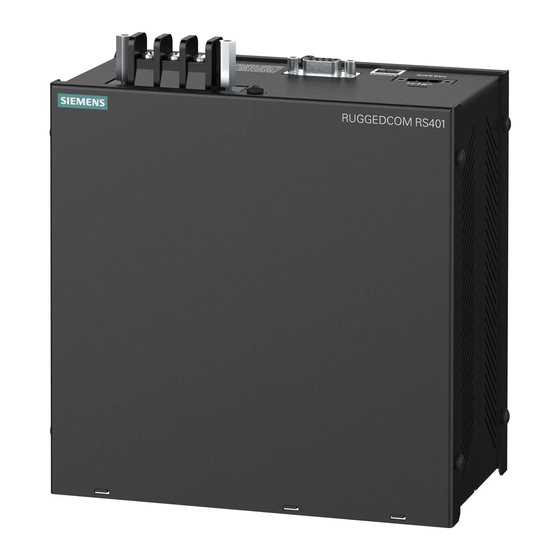
Introduction Introduction The RUGGEDCOM RS401 is an industrially hardened, serial device server with an integrated, fully managed Ethernet switch, designed to operate reliably in electrically harsh and climatically demanding environments. Featuring an integrated 4 port serial server, a 4 port managed Ethernet switch, and an optional V.90 modem, the RS401 is able to interconnect multiple types of intelligent electronic devices (IEDs) that have different methods of communications. -
Page 10: Description
Chapter 1 RUGGEDCOM RS401 Introduction Installation Guide Cyber Security Features • Multi-level user passwords • SSH/SSL (128-bit encryption) • Enable/disable ports, MAC based port security • Port based network access control (802.1x) • VLAN (802.1Q) to segregate and secure network traffic •... - Page 11 Chapter 1 Installation Guide Introduction Figure 1: RUGGEDCOM RS401 Modules 1. POWER LED 2. ALARM LED 3. RESET Button 4. Ethernet Port Status LEDs 5. Serial Port Status LEDs 6. Power Supply Terminal Block 7. Surge Ground Terminal 8. RS232 Serial Console Port (DB9) 9. Modem Port (Optional) 10. Failsafe Alarm Relay POWER LED Illuminates when power is being supplied to the device.
- Page 12 Installation Guide Communication Ports Receive and transmit data, as well as provide access to the RUGGEDCOM ROS Web interface. For more information about the various ports available for the RUGGEDCOM RS401, refer to Chapter 3, Communication Ports RS-232 Console Port The serial console port is for interfacing directly with the device and accessing initial management functions.
-
Page 13: Installing The Device
Installation Guide Installing the Device Installing the Device This section describes how to install and connect to the RUGGEDCOM RS401. WARNING! Radiation hazard – risk of serious personal injury. This product contains a laser system and is classified as a CLASS 1 LASER PRODUCT. Use of controls or adjustments or performance of procedures other than those specified herein may result in hazardous radiation exposure. -
Page 14: Mounting The Device On A Din Rail
Chapter 2 RUGGEDCOM RS401 Installing the Device Installation Guide NOTE For detailed dimensions of the device with either DIN rail or panel hardware installed, refer to Chapter 5, Dimension Drawings CONTENTS • Section 2.1.1, “Mounting the Device on a DIN Rail” •... -
Page 15: Connecting Power
RUGGEDCOM RS401 Chapter 2 Installation Guide Installing the Device Figure 3: Panel Mounting 1. Screw 2. Panel/DIN Rail Adaptor Install the supplied screws to secure the adapters to the panel. Section 2.2 Connecting Power The RS401 supports a single integrated high AC/DC or low DC power supply NOTE •... -
Page 16: Connecting Ac Power
Chapter 2 RUGGEDCOM RS401 Installing the Device Installation Guide • Section 2.2.2, “Connecting DC Power” Section 2.2.1 Connecting AC Power To connect a high AC power supply to the device, do the following: CAUTION! Electrical hazard – risk of damage to equipment. Before testing the dielectric strength (HIPOT) in the field, remove the braided ground cable connected to the surge ground terminal and chassis ground. -
Page 17: Connecting The Failsafe Alarm Relay
RUGGEDCOM RS401 Chapter 2 Installation Guide Installing the Device This cable connects transient suppression circuitry to chassis ground and must be removed in order to avoid damage to transient suppression circuitry during testing. Connect the positive wire from the power source to the positive/hot (+/H) terminal on the terminal block. -
Page 18: Grounding The Device
Chapter 2 RUGGEDCOM RS401 Installing the Device Installation Guide Figure 6: Failsafe Alarm Relay Wiring 1. Normally Open 2. Common 3. Normally Closed Section 2.4 Grounding the Device The RS401 chassis ground terminal uses a #6-32 screw. It is recommended to terminate the ground connection with a #6 ring lug and torque it to 1.7 N·m (15 lbf·in). -
Page 19: Connecting To The Device
Installation Guide Installing the Device Siemens also does not recommend using copper Ethernet ports to interface with devices in the field across distances that could produce high levels of ground potential rise (i.e. greater than 2500 V), during line-to-ground fault conditions. - Page 20 RUGGEDCOM RS401 Chapter 2 Installation Guide Installing the Device Connecting to the Device...
-
Page 21: Communication Ports
RUGGEDCOM RS401 Chapter 3 Installation Guide Communication Ports Communication Ports The RS401 can be equipped with various types of communication ports to enhance its abilities and performance. To determine which ports are equipped on the device, refer to the factory data file available through ROS. For more information on how to access the factory data file, refer to the ROS User Guide for the RS401. -
Page 22: Fiber Optic Ethernet Ports
Chapter 3 RUGGEDCOM RS401 Communication Ports Installation Guide RJ45 receptacles at either end. Ground loops can cause excessive noise and interference, but more importantly, create a potential shock hazard that can result in serious injury. LEDs Each port features a Speed and Link LED that indicates the state of the port. -
Page 23: Modem Port
RUGGEDCOM RS401 Chapter 3 Installation Guide Communication Ports Port Types Figure 12: LC Port Figure 11: MTRJ Port 1. Tx Connector 2. Rx Connector 1. Tx Connector 2. Rx Connector Figure 13: SC Port Figure 14: ST Port 1. Tx Connector 2. Rx Connector 1. Tx Connector 2. Rx Connector Specifications For specifications on the available fiber optic Ethernet ports, refer to Section 4.4, “Fiber Optic Ethernet Port... -
Page 24: Serial Ports
Chapter 3 RUGGEDCOM RS401 Communication Ports Installation Guide NOTE This product meets the applicable Industry Canada technical specifications. The Ringer Equivalence Number is an indication of the maximum number of devices allowed to be connected to a telephone interface. The termination on an interface may consist of any combination of devices subject only to the requirement that the sum of the RENs of all the devices does not exceed five. -
Page 25: Serial Rs232/Rs485/Rs422 Db9 Ports
RUGGEDCOM RS401 Chapter 3 Installation Guide Communication Ports Name Description Reserved (Do Not Connect) Transmit Data Receive Data Reserved (Do Not Connect) Common Ground Reserved (Do Not Connect) Reserved (Do Not Connect) Figure 16: RS232 DB9 Serial Console Port Reserved (Do Not Connect) Reserved (Do Not Connect) Section 3.4.2... -
Page 26: Serial Rs232/Rs485/Rs422 Rj45 Ports
Chapter 3 RUGGEDCOM RS401 Communication Ports Installation Guide Section 3.4.3 Serial RS232/RS485/RS422 RJ45 Ports The RS401 can be equipped with serial RS232/RS485/RS422 RJ45 ports. Each port can be set individually through the ROS operating system to operate in RS232, RS485 or RS422 mode. For more information, refer to the ROS User Guide for the RS401. -
Page 27: Connecting Multiple Rs485 Devices
RUGGEDCOM RS401 Chapter 3 Installation Guide Communication Ports Terminal Description Positive Negative Common (Isolated Ground) Figure 19: Serial Insulated Terminal Port Section 3.4.5 Connecting Multiple RS485 Devices Each RS485 port can communicate with multiple RS485 devices by wiring devices together in sequence over a single twisted pair with transmit and receive signals on the same two wires (half duplex). - Page 28 Chapter 3 RUGGEDCOM RS401 Communication Ports Installation Guide 120Ω 10nF 120Ω 10nF Figure 20: Recommended RS485 Wiring Connecting Multiple RS485 Devices...
-
Page 29: Technical Specifications
RUGGEDCOM RS401 Chapter 4 Installation Guide Technical Specifications Technical Specifications This section details the specifications and operating conditions of the device. CONTENTS • Section 4.1, “Power Supply Specifications” • Section 4.2, “Failsafe Alarm Relay Specifications” • Section 4.3, “Copper Ethernet Port Specifications” •... -
Page 30: Copper Ethernet Port Specifications
To convert from average to peak, add 3 dBm. To convert from peak to average, subtract 3 dBm. Maximum segment length is greatly dependent on factors such as fiber quality, and the number of patches and splices. Consult a Siemens sales associate when determining maximum segment distances. -
Page 31: Fast Ethernet (100 Mbps) Optical Specifications
To convert from average to peak, add 3 dBm. To convert from peak to average, subtract 3 dBm. Maximum segment length is greatly dependent on factors such as fiber quality, and the number of patches and splices. Consult a Siemens sales associate when determining maximum segment distances. -
Page 32: Operating Environment
Chapter 4 RUGGEDCOM RS401 Technical Specifications Installation Guide Section 4.6 Operating Environment Parameter Range Comments Ambient Operating Temperature -40 to 85 °C Measured from a 30 cm (12 in) radius surrounding the center of the (-40 to 185 °F) enclosure. Ambient Relative Humidity... -
Page 33: Dimension Drawings
RUGGEDCOM RS401 Chapter 5 Installation Guide Dimension Drawings Dimension Drawings NOTE All dimensions are in millimeters, unless otherwise stated. 172.0 88.6 Figure 21: Overall Dimensions... - Page 34 Chapter 5 RUGGEDCOM RS401 Dimension Drawings Installation Guide 125.7 Figure 22: Panel and Din Rail Mount Dimensions...
-
Page 35: Certification
RUGGEDCOM RS401 Chapter 6 Installation Guide Certification Certification The RUGGEDCOM RS401 device has been thoroughly tested to guarantee its conformance with recognized standards and has received approval from recognized regulatory agencies. CONTENTS • Section 6.1, “Agency Approvals” • Section 6.2, “FCC Compliance”... -
Page 36: Emi And Environmental Type Tests
Chapter 6 RUGGEDCOM RS401 Certification Installation Guide Section 6.4 EMI and Environmental Type Tests The RS401 has passed the following EMI and environmental tests. IEC 61850-3 EMI Type Tests Severity Test Description Test Levels Levels IEC 61000-4-2 Enclosure Contact +/- 8 kV... - Page 37 RUGGEDCOM RS401 Chapter 6 Installation Guide Certification Severity Test Description Test Levels Levels DC Power ports 5 kV AC Power ports 5 kV IEEE 1613 (C37.90.x) EMI Immunity Type Tests NOTE The RS401 meets Class 2 requirements for an all-fiber configuration and Class 1 requirements for copper ports.
- Page 38 RUGGEDCOM RS401 Chapter 6 Installation Guide Certification EMI and Environmental Type Tests...