Siemens RUGGEDCOM RMC30 Installation Manual
2-port serial-to-ethernet server
Hide thumbs
Also See for RUGGEDCOM RMC30:
- Installation manual (40 pages) ,
- Technical guidance notes (29 pages)

Related Manuals for Siemens RUGGEDCOM RMC30


Summary of Contents for Siemens RUGGEDCOM RMC30
- Page 1 Preface Introduction Installing the Device RUGGEDCOM RMC30 Communication Ports Technical Specifications Dimension Drawings Installation Guide Certification 01/2017 RC1008-EN-05...
-
Page 2: Security Information
Warranty Siemens warrants this product for a period of five (5) years from the date of purchase, conditional upon the return to factory for maintenance during the warranty term. This product contains no user-serviceable parts. Attempted service by unauthorized personnel shall render all warranties null and void. - Page 3 RUGGEDCOM RMC30 Installation Guide Contacting Siemens Address Telephone E-mail Siemens Canada Ltd Toll-free: 1 888 264 0006 ruggedcom.info.i-ia@siemens.com Industry Sector Tel: +1 905 856 5288 300 Applewood Crescent Fax: +1 905 856 1995 Concord, Ontario www.siemens.com/ruggedcom Canada, L4K 5C7...
- Page 4 RUGGEDCOM RMC30 Installation Guide...
-
Page 5: Table Of Contents
RUGGEDCOM RMC30 Installation Guide Table of Contents Table of Contents Preface ......................Alerts ..............................vii Related Documents ..........................viii Accessing Documentation ........................viii Training ............................viii Customer Support ..........................viii Chapter 1 Introduction ..................... 1.1 Feature Highlights ........................1 1.2 Description ........................... 2 Chapter 2 Installing the Device .................. - Page 6 RUGGEDCOM RMC30 Table of Contents Installation Guide 4.5 Mechanical Specifications ......................20 Chapter 5 Dimension Drawings ..................Chapter 6 Certification ....................6.1 Approvals ........................... 23 6.1.1 CSA ..........................23 6.1.2 European Union (EU) ....................... 24 6.1.3 FCC ..........................24 6.1.4 FDA/CDRH ........................
-
Page 7: Preface
Installation Guide Preface Preface This guide describes the RUGGEDCOM RMC30. It describes the major features of the device, installation, commissioning and important technical specifications. It is intended for use by network technical support personnel who are responsible for the installation, commissioning and maintenance of the device. -
Page 8: Related Documents
Mobile App Install the Industry Online Support app by Siemens AG on any Android, Apple iOS or Windows mobile device and be able to: • Access Siemens' extensive library of support documentation, including FAQs and manuals • Submit SRs or check on the status of an existing SR •... -
Page 9: Introduction
An operating temperature range of -40 to 85°C (-40 to 185°F) without the use of internal cooling fans allows it to be placed in almost any location. The RUGGEDCOM RMC30 is compliant with EMI and environmental standards for utility substations, industrial manufacturing, process and control and intelligent transportation systems applications. -
Page 10: Description
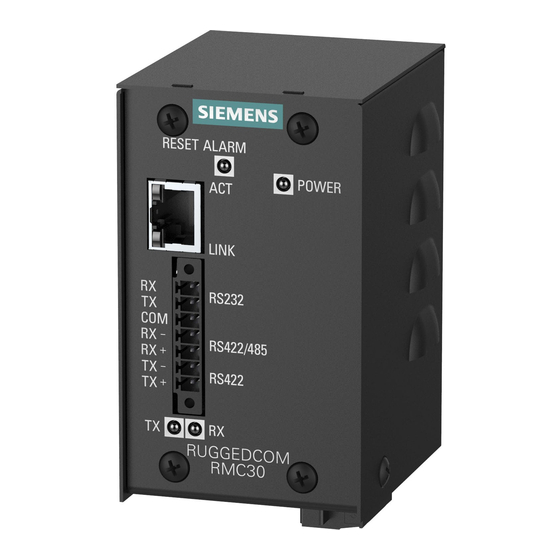
Section 1.2 Description The RUGGEDCOM RMC30 features various ports, controls and indicator LEDs on the display panel for connecting, configuring and troubleshooting the device. The display panel can be located on the rear, front or top of the device, depending on the mounting configuration. -
Page 11: Communication Ports
A pluggable terminal. For more information, refer to: • Section 2.2, “Connecting Power” • Section 4.1, “Power Supply Specifications” Communication Ports Receive and transmit data. For more information about the various ports available for the RUGGEDCOM RMC30, refer to Chapter 3, Communication Ports Description... - Page 12 Chapter 1 RUGGEDCOM RMC30 Introduction Installation Guide Description...
-
Page 13: Installing The Device
Section 2.1 Mounting the Device The RUGGEDCOM RMC30 is designed for maximum mounting and display flexibility. It can be equipped with connectors that allow it to be installed in a 35 mm (1.4 in) DIN rail or directly on a panel. -
Page 14: Mounting The Device On A Din Rail
Chapter 2 RUGGEDCOM RMC30 Installing the Device Installation Guide IMPORTANT! Heat generated by the device is channeled outwards to the enclosure. As such, it is recommended that 2.5 cm (1 in) of space be maintained on all open sides of the device to allow for some convectional airflow. -
Page 15: Mounting The Device To A Panel
Insert the device into the adapter. Make sure the device is secured between the two metal clips. Section 2.2 Connecting Power The RUGGEDCOM RMC30 supports a single integrated high AC/DC or low DC power supply NOTE • For 110/230 VAC rated equipment, an appropriately rated AC circuit breaker must be installed. -
Page 16: Connecting Ac Power
Ground. Note that all line-to-ground transient protection circuitry will be disabled. IMPORTANT! Siemens requires the use of external surge protection in VDSL applications where the line may be subject to surges greater than that for which the device is rated. Use the following specifications as a guide for VDSL external surge protection: •... -
Page 17: Connecting Dc Power
RUGGEDCOM RMC30 Chapter 2 Installation Guide Installing the Device Figure 4: Terminal Block Wiring 1. Positive/Live (+/L) Terminal 2. Negative/Neutral (-/N) Terminal 3. Surge Ground Terminal 4. Braided Ground Cable Connect the negative wire from the power source to the negative/neutral (-/N) terminal on the terminal block. -
Page 18: Connecting To The Device
Connecting to the Device The following describes the various methods for accessing the RUGGEDCOM ROS console and Web interfaces on the device. For more detailed instructions, refer to the RUGGEDCOM ROS User Guide for the RUGGEDCOM RMC30. RS232/RS422/RS485 Serial Console Terminal Connect a PC or terminal directly to the RS232 serial terminals to access the boot-time control and RUGGEDCOM ROS console interface. -
Page 19: Resetting The Device
Section 2.4 Resetting the Device The RUGGEDCOM RMC30 can be reset (rebooted) using the RESET button. The RESET button is recessed and can only be reached using a pin or small screwdriver. To reset the device, quickly press and release the RESET button with a pin. - Page 20 Chapter 2 RUGGEDCOM RMC30 Installing the Device Installation Guide Resetting the Device...
-
Page 21: Communication Ports
RUGGEDCOM RMC30 Chapter 3 Installation Guide Communication Ports Communication Ports The RUGGEDCOM RMC30 can be equipped with various types of communication ports to enhance its abilities and performance. Figure 6: Port Assignment 1. Port 1 2. Port 2 Port Type Copper Ethernet Port RS232/RS485/RS422 Serial Terminal CONTENTS •... -
Page 22: Specifications
Chapter 3 RUGGEDCOM RMC30 Communication Ports Installation Guide WARNING! Electric shock hazard – risk of serious personal injury and/or equipment interference. If shielded cables are used, make sure the shielded cables do not form a ground loop via the shield wire and the RJ45 receptacles at either end. -
Page 23: Serial Terminal
IMPORTANT! The RS232 port is intended for point-to-point applications only. In adherence to the EIA/TIA guidelines for RS232 communications, the following is recommended by Siemens: • Always use shielded cabling to minimize the effects of ambient electrical noise • Although greater distances are possible, limit the cable length to 15 m (49 ft) or less for more reliable communications •... -
Page 24: Rs485/422 Data Ports
NOTE The RUGGEDCOM RMC30 features built-in pull-up and pull-down resistors. As such, external bias resistors are only recommended when connecting the RUGGEDCOM RMC30 to third-party serial devices that do not have built-in pull-up and pull-down resistors. - Page 25 The following shows the recommended RS485 wiring. 120Ω 10nF Figure 10: Recommended RS485 Wiring 1. RUGGEDCOM RMC30 Device With Built-In Termination 2. Common (Isolated Ground) 3. Negative 4. Positive 5. Shield to Earth (Connected At a Single Point) 6. RS485 Devices (32 Total) RS485/422 Data Ports...
- Page 26 Chapter 3 RUGGEDCOM RMC30 Communication Ports Installation Guide RS485/422 Data Ports...
-
Page 27: Technical Specifications
RUGGEDCOM RMC30 Chapter 4 Installation Guide Technical Specifications Technical Specifications This section provides important technical specifications related to the device and available modules. CONTENTS • Section 4.1, “Power Supply Specifications” • Section 4.2, “Copper Ethernet Port Specifications” • Section 4.3, “Supported Networking Standards”... -
Page 28: Supported Networking Standards
Chapter 4 RUGGEDCOM RMC30 Technical Specifications Installation Guide Typical distance. Dependent on the number of connectors and splices. RMS 1 minute. Section 4.3 Supported Networking Standards Parameter 10Base-FL 100Base-FX Notes IEEE 802.3 Yes No 10Base-T IEEE 802.3x Yes No Yes No Full Duplex, Flow Control Section 4.4... -
Page 29: Dimension Drawings
RUGGEDCOM RMC30 Chapter 5 Installation Guide Dimension Drawings Dimension Drawings NOTE All dimensions are in millimeters, unless otherwise stated. 92.8 80.1 73.7 62.2 58.4 70.7 Figure 11: Overall Dimensions... - Page 30 Chapter 5 RUGGEDCOM RMC30 Dimension Drawings Installation Guide 67.3 62.2 96.1 58.4 82.2 35.6 11.4 Figure 12: Panel Mount Dimensions...
-
Page 31: Certification
RUGGEDCOM RMC30 Chapter 6 Installation Guide Certification Certification The RUGGEDCOM RMC30 device has been thoroughly tested to guarantee its conformance with recognized standards and has received approval from recognized regulatory agencies. CONTENTS • Section 6.1, “Approvals” • Section 6.2, “EMC and Environmental Type Tests”... -
Page 32: European Union (Eu)
Information Technology Equipment – Radio disturbance characteristics – Limits and methods of measurement The device is marked with a CE marking and can be used throughout the European community. A copy of the CE Declaration of Conformity is available from Siemens Canada Ltd. For contact information, refer to “Contacting Siemens ”... -
Page 33: Other Approvals
• IEC 61850-3 Communications Networks and Systems for Power Utility Automation – Part 3: General Requirements Section 6.2 EMC and Environmental Type Tests The RUGGEDCOM RMC30 has passed the following EMC and environmental tests. IEC 61850-3 Type Tests Test Description Test Levels... - Page 34 AC Power Ports 5 kV Siemens specified severity level. IEEE 1613 EMC Immunity Type Tests NOTE The RUGGEDCOM RMC30 meets Class 2 requirements for an all-fiber configuration and Class 1 requirements for copper ports. Description Test Levels Enclosure Contact ± 8 kV Enclosure Air ±...
- Page 35 RUGGEDCOM RMC30 Chapter 6 Installation Guide Certification Environmental Type Tests Test Description Test Levels Severity Levels IEC 60068-2-1 Cold Temperature Test Ad -40 °C (-40 °F), 16 Hours IEC 60068-2-2 Dry Heat Test Bd 85 °C (185 °F), 16 Hours...
- Page 36 Chapter 6 RUGGEDCOM RMC30 Certification Installation Guide EMC and Environmental Type Tests...