
Related Manuals for Siemens RUGGEDCOM RS401


Summary of Contents for Siemens RUGGEDCOM RS401
- Page 1 Installation Manual SIMATIC NET Rugged Ethernet Switches RUGGEDCOM RS401 Edition 02/2020 https://www.siemens.com...
- Page 2 Preface Introduction Installing the Device SIMATIC NET Device Management Rugged Ethernet Switches RUGGEDCOM RS401 Communication Ports Technical Specifications Installation Manual Certification 02/2020 C79000-G8976-1017-10...
- Page 3 Note the following: WARNING Siemens products may only be used for the applications described in the catalog and in the relevant technical documentation. If products and components from other manufacturers are used, these must be recommend- ed or approved by Siemens. Proper transport, storage, installation, assembly, commissioning, operation and maintenance are required to ensure that the products operate safely and without any problems.
-
Page 4: Table Of Contents
Accessing Documentation ....................... v Disclaimer of Liability ......................v Registered Trademarks ......................v Training ..........................vi Customer Support ........................vi Contacting Siemens ....................... vii Introduction ........................... 1 Feature Highlights ....................1 Description ......................3 Required Tools and Materials ................. 4 Decommissioning and Disposal ................ - Page 5 European Union (EU) ..................35 6.1.3 FCC ........................36 6.1.4 FDA/CDRH ......................36 6.1.5 ISED ........................36 6.1.6 ACMA ........................37 6.1.7 RoHS ........................37 6.1.8 Other Approvals ....................37 EMC and Environmental Type Tests ..............38 RUGGEDCOM RS401 Installation Manual, 02/2020, C79000-G8976-1017-10...
-
Page 6: Preface
However, deviations between the product and the documentation may exist. Siemens shall not be liable for any errors or omissions contained herein or for conse- quential damages in connection with the furnishing, performance, or use of this ma- terial. -
Page 7: Training
Siemens Sales representative. Customer Support Customer support is available 24 hours, 7 days a week for all Siemens customers. For technical support or general information, contact Siemens Customer Support through any of the following methods: Online Visit http://www.siemens.com/automation/support-request... -
Page 8: Contacting Siemens
Contacting Siemens Address Siemens AG Industry Sector 300 Applewood Crescent Concord, Ontario Canada, L4K 5C7 Telephone Toll-free: 1 888 264 0006 Tel: +1 905 856 5288 Fax: +1 905 856 1995 E-Mail ruggedcom.info.i-ia@siemens.com https://www.siemens.com RUGGEDCOM RS401 Installation Manual, 02/2020, C79000-G8976-1017-10... - Page 9 Preface Contacting Siemens viii RUGGEDCOM RS401 Installation Manual, 02/2020, C79000-G8976-1017-10...
-
Page 10: Introduction
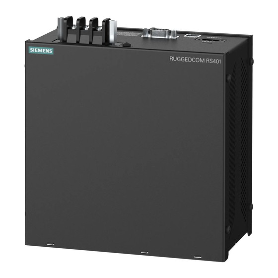
Introduction The RUGGEDCOM RS401 is an industrially hardened, serial device server with an in- tegrated, fully managed Ethernet switch, designed to operate reliably in electrical- ly harsh and climatically demanding environments. Featuring an integrated 4 port serial server, a 4 port managed Ethernet switch, and an optional V.90 modem, the RUGGEDCOM RS401 is able to interconnect multiple types of intelligent electronic devices (IEDs) that have different methods of communications. - Page 11 Fully integrated power supplies (no external adaptors) • Popular low voltage ranges: 24 VDC (10-36 VDC), 48 VDC (36-59 VDC) • Universal high-voltage range: 88-300 VDC or 85-264 VAC • CSA/UL 60950 safety approved to 85 °C (185 °F) RUGGEDCOM RS401 Installation Manual, 02/2020, C79000-G8976-1017-10...
-
Page 12: Description
Introduction 1.2 Description Description The RUGGEDCOM RS401 features various ports, controls and indicator LEDs on the front panel for connecting, configuring and troubleshooting the device. POWER LED ALARM LED RESET Button Ethernet Port Status LEDs Serial Port Status LEDs Power Supply Terminal Block... -
Page 13: Required Tools And Materials
Power (Page 16)" "Power Supply Specifications (Page 29)" Required Tools and Materials The following tools and materials are required to install the RUGGEDCOM RS401: Tools/Materials Purpose AC or DC power cord (16 AWG) For connecting power to the device. -
Page 14: Cabling Recommendations
Siemens also does not recommend using copper Ethernet ports to interface with de- vices in the field across distances that could produce high levels of ground potential rise (i.e. - Page 15 Introduction 1.5.2 Supported Fiber Optic Cables Cable Type Wavelength (nm) Modal Band- Distance (m) width (MHz·km) 100Base-FX 1000Base-SX 10GBase-SR 1300 2000 — — Laser optimized. RUGGEDCOM RS401 Installation Manual, 02/2020, C79000-G8976-1017-10...
-
Page 16: Installing The Device
Installing the Device This section describes how to install and connect to the RUGGEDCOM RS401. WARNING Radiation hazard – risk of serious personal injury This product contains a laser system and is classified as a CLASS 1 LASER PRODUCT. Use of controls or adjustments or performance of procedures other than those speci- fied herein may result in hazardous radiation exposure. -
Page 17: Unpacking The Device
If any item is missing or damaged, contact Siemens for assistance. Mounting the Device The RUGGEDCOM RS401 is designed for maximum mounting and display flexibility. It can be equipped with connectors that allow it to be installed on a DIN rail or directly on a panel. -
Page 18: Mounting The Device On A Din Rail
2.3.1 Mounting the Device on a DIN Rail The RUGGEDCOM RS401 can be ordered with panel/DIN rail adapters preinstalled on each side of the chassis. Use the adapters to mount the device to a standard 35 mm (1.4 in) IEC/EN 60715 or TS35 DIN rail. - Page 19 Mounting the Device to a DIN Rail (Side Panel Mount Option) Install one of the supplied #8-32 lock screws on either side of the device to se- cure the adapters to the DIN rails. RUGGEDCOM RS401 Installation Manual, 02/2020, C79000-G8976-1017-10...
- Page 20 Removing the Device from a DIN Rail (Front Panel Mount Option) Panel/DIN Rail Adapter DIN Rail Screw Figure 2.4 Removing the Device from a DIN Rail (Side Panel Mount Option) Lift the device off the DIN rail. RUGGEDCOM RS401 Installation Manual, 02/2020, C79000-G8976-1017-10...
-
Page 21: Mounting The Device To A Panel
2.3.2 Mounting the Device to a Panel For panel installations, the RUGGEDCOM RS401 can be equipped with panel/DIN rail adapters pre-installed on each side of the chassis. The adapters allow the device to be attached to a panel using screws. - Page 22 To mount the device to a panel, do the following: Place the device against the panel and align the adapters with the mounting holes. Screw Panel/DIN Rail Adaptor Figure 2.5 Panel Mounting (Front Mount Orientation) RUGGEDCOM RS401 Installation Manual, 02/2020, C79000-G8976-1017-10...
-
Page 23: Connecting The Failsafe Alarm Relay
NO contact and closes the NC (Normally Closed) contact. Note Control of the failsafe relay output is configurable through RUGGEDCOM RS401 . One common application for this relay is to signal an alarm if a power failure occurs. -
Page 24: Grounding The Device
Figure 2.7 Failsafe Alarm Relay Wiring Grounding the Device The RUGGEDCOM RS401 chassis ground terminal uses a #6-32 screw. It is recom- mended to terminate the ground connection with a #6 ring lug and torque it to 1.7 N·m (15 lbf·in). -
Page 25: Connecting Power
Installing the Device 2.6 Connecting Power Connecting Power The RUGGEDCOM RS401 supports a single integrated high AC/DC or low DC power supply Note • For 88-300 VDC rated equipment, an appropriately rated circuit breaker must be installed. • For 100-240 VAC rated equipment, an appropriately rated circuit breaker must be installed. -
Page 26: 2.6.2 Connecting Dc Power
This cable connects transient suppression circuitry to chassis ground and must be removed in order to avoid damage to transient suppression circuitry during testing. RUGGEDCOM RS401 Installation Manual, 02/2020, C79000-G8976-1017-10... - Page 27 Connect the ground terminal on the power source to the chassis ground termi- nal on the device. For more information, refer to "Grounding the Device (Page 15)". RUGGEDCOM RS401 Installation Manual, 02/2020, C79000-G8976-1017-10...
-
Page 28: Device Management
Communication Ports Connect any of the available Ethernet ports on the device to a management switch and access the RUGGEDCOM RS401 console and Web interfaces via the device's IP address. For more information about available ports, refer to "Communication Ports (Page 21)". -
Page 29: Configuring The Device
Once the device is installed and connected to the network, it must be configured. All configuration management is done via the RUGGEDCOM ROS interface. For more in- formation about configuring the device, refer to the RUGGEDCOM ROS Configura- tion Manual associated with the installed software release. RUGGEDCOM RS401 Installation Manual, 02/2020, C79000-G8976-1017-10... -
Page 30: Communication Ports
To determine which ports are equipped on the device, refer to the factory data file available through RUGGEDCOM RS401 . For more information on how to access the factory data file, refer to the RUGGEDCOM ROS Configuration Manual for the RUGGEDCOM RS401. -
Page 31: Fiber Optic Ethernet Ports
"Copper Ethernet Port Specifications (Page 29)". Fiber Optic Ethernet Ports Fiber optic Ethernet ports are available with either MTRJ (Mechanical Transfer Reg- istered Jack), LC (Lucent Connector), SC (Standard or Subscriber Connector) or ST RUGGEDCOM RS401 Installation Manual, 02/2020, C79000-G8976-1017-10... -
Page 32: Modem Port
Port Specifications (Page 30)". Modem Port The RUGGEDCOM RS401 can optionally be equipped with a V.90 Modem connection for PPP (Point-to-Point Protocol) connections. For information about how to config- ure and operate the modem, refer to the RUGGEDCOM ROS Configuration Manual for the RUGGEDCOM RS401. -
Page 33: Serial Ports
RENs of all the devices does not exceed five. Serial Ports The RUGGEDCOM RS401 supports RJ45 or DB9 serial ports, which can be run in RS232, RS485 or RS422 mode. Note On power-up, all serial ports default to RS485 mode. -
Page 34: 4.4.2 Serial Rs232/Rs485/Rs422 Db9 Ports
Communication Ports 4.4.2 Serial RS232/RS485/RS422 DB9 Ports ing with an another DCE device, such as another RUGGEDCOM RS401, the RX and TX pins must be crossed-over using, for example, a NULL modem cable. The following is the pin-out description for the RS232 DB9 ports: ... -
Page 35: 4.4.3 Serial Rs232/Rs485/Rs422 Rj45 Ports
Serial RS232/RS485/RS422 RJ45 Ports The RUGGEDCOM RS401 can be equipped with serial RS232/RS485/RS422 RJ45 ports. Each port can be set individually through the RUGGEDCOM RS401 operating sys- tem to operate in RS232, RS485 or RS422 mode. For more information, refer to the RUGGEDCOM ROS Configuration Manual for the RUGGEDCOM RS401. -
Page 36: 4.4.5 Connecting Multiple Rs485 Devices
The shield should be connected to earth ground at a single point to avoid loop currents. • The twisted pair should be terminated at each end of the chain. The following shows the recommended RS485 wiring. RUGGEDCOM RS401 Installation Manual, 02/2020, C79000-G8976-1017-10... - Page 37 Communication Ports 4.4.5 Connecting Multiple RS485 Devices 120Ω 10nF 120Ω 10nF RUGGEDCOM RS401 Common (Isolated Ground) Negative Positive Shield to Earth (Connected At a Single Point) RS485 Devices (32 Total) Figure 4.12 Recommended RS485 Wiring RUGGEDCOM RS401 Installation Manual, 02/2020, C79000-G8976-1017-10...
-
Page 38: Technical Specifications
1 A @ 30 VDC, 0.3 A @ 80 VDC 0.2 A @ 250 VAC 0.6 A @ 125 VAC Copper Ethernet Port Specifications The following details the specifications for copper Ethernet ports that can be ordered with the RUGGEDCOM RS401. Cable Maximum Isola- Speed... -
Page 39: Fiber Optic Ethernet Port Specifications
To convert from average to peak, add 3 dBm. To convert from peak to average, subtract 3 dBm. Maximum segment length is greatly dependent on factors such as fiber quality, and the number of patches and splices. Consult a Siemens sales associate when determining maximum segment distances. Fast Ethernet (100 Mbps) Optical Specifications... -
Page 40: Serial Port Specifications
1200 m (3937 ft) RS232/RS485/RS422 Shielded Twisted-Pair 1200 m (3937 ft) RJ45 Operating Environment The RUGGEDCOM RS401 is rated to operate under the following environmental con- ditions. Ambient Operating Tempera- -40 to 85 °C (-40 to 185 °F) ture Ambient Storage Temperature -40 to 85 °C (-40 to 185 °F) - Page 41 Technical Specifications 5.8 Dimension Drawings 172.0 88.6 Figure 5.1 Overall Dimensions RUGGEDCOM RS401 Installation Manual, 02/2020, C79000-G8976-1017-10...
- Page 42 Technical Specifications 5.8 Dimension Drawings 98.8 134.4 12.7 Figure 5.2 Panel and Din Rail Mount Dimensions (Front Mount Option) RUGGEDCOM RS401 Installation Manual, 02/2020, C79000-G8976-1017-10...
- Page 43 Technical Specifications 5.8 Dimension Drawings 125.7 Figure 5.3 Panel and Din Rail Mount Dimensions (Side Mount Option) RUGGEDCOM RS401 Installation Manual, 02/2020, C79000-G8976-1017-10...
-
Page 44: Certification
Certification The RUGGEDCOM RS401 device has been thoroughly tested to guarantee its confor- mance with recognized standards and has received approval from recognized regula- tory agencies. Approvals This section details the standards to which the RUGGEDCOM RS401 complies. 6.1.1 This device is certified by the CSA Group to meet the requirements of the following standards: •... -
Page 45: 6.1.3 Fcc
Respect to the Restriction of Hazardous Substances The device is marked with a CE marking and can be used throughout the European community. A copy of the CE Declaration of Conformity is available from Siemens AG. For contact information, refer to "Contacting Siemens (Page vii)". -
Page 46: Acma
6.1.7 RoHS This device is declared by Siemens AG to meet the requirements of the following Ro- HS (Restriction of Hazardous Substances) directives for the restricted use of certain hazardous substances in electrical and electronic equipment: •... -
Page 47: Emc And Environmental Type Tests
IEC 61000-6-2 Electromagnetic Compatibility (EMC) – Part 6-2: Generic Standards – Immunity for Industrial Environments EMC and Environmental Type Tests The RUGGEDCOM RS401 has passed the following EMC and environmental tests. IEC 61850-3 EMC Type Tests Test Description Test Levels... - Page 48 AC Power Ports 5 kV IEEE 1613 (C37.90.x) EMC Immunity Type Tests Note The RUGGEDCOM RS401 meets Class 2 requirements for an all-fiber configuration and Class 1 requirements for copper ports. Description Test Levels Enclosure Contact ±8 kV Enclosure Air ±15 kV...
- Page 49 Certification 6.2 EMC and Environmental Type Tests RUGGEDCOM RS401 Installation Manual, 02/2020, C79000-G8976-1017-10...
- Page 50 Further Information Siemens RUGGEDCOM https://www.siemens.com/ruggedcom Industry Online Support (service and support) https://support.industry.siemens.com Industry Mall https://mall.industry.siemens.com Siemens AG Digital Industry Process Automation Postfach 48 48 90026 NÜRNBERG GERMANY...