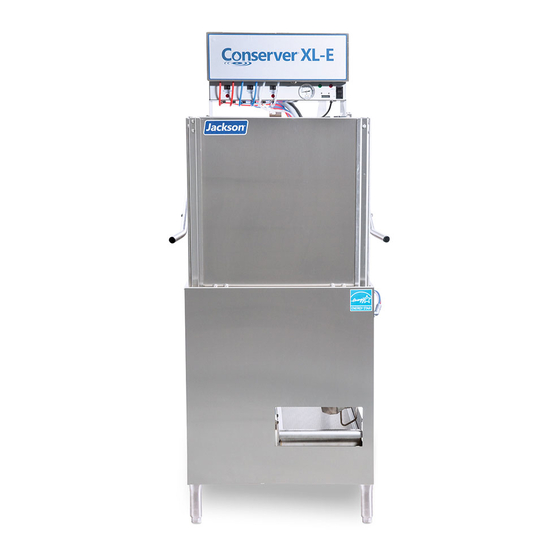
Jackson CONSERVER XL-E Installation, Operation And Service Manual
Door-type dishmachine; chemical-sanitizing, single-rack
Hide thumbs
Also See for CONSERVER XL-E:
- Installation quick manual (2 pages) ,
- Installation, operation and service manual (64 pages) ,
- Installation, operation and service manual (70 pages)

Related Manuals for Jackson CONSERVER XL-E


Summary of Contents for Jackson CONSERVER XL-E
- Page 1 INSTALLATION, OPERATION, AND SERVICE MANUAL CONSERVER XL-E, XL-E-LTH, & XL HH DISHMACHINES ® Conserver XL-E/XL-E-LTH/XL HH Manual • 07610-003-92-84-Q ®...
- Page 2 The labor to repair or replace such failed part will be paid by Jackson WWS, within the continental United States, Hawaii, and Canada, during the warranty period provided a Jackson WWS authorized service agency, or those having prior authorization from the factory, performs the service.
- Page 3 REVISION HISTORY Revision Revision Made by Applicable ECNs Details Letter Date 1-6-14 8241 Release to production. 8-18-14 8305 Removed pg 17, updated part on page 20. 8-29-14 Updated part on pg. 27. Added 208 volt schematic on page 32. Updated available electrical characteristics on pg. 4. 10-14-14 Updated Dimensions pg.
- Page 4 NOMENCLATURE Conserver XL-E ® Door-type dishmachine; chemical-sanitizing, single-rack. Conserver XL-E-LTH ® Door-type dishmachine; chemical-sanitizing, single-rack, with booster heater. Conserver XL HH ® Door-type dishmachine; chemical-sanitizing, single-rack with high hood. The manufacturer provides technical support for all of the dishmachines detailed in this manual.
-
Page 5: Table Of Contents
TABLE OF CONTENTS GUIDES Symbols ............................1 Abbreviations & Acronyms ......................1 SPECIFICATIONS XL-E Dimensions ........................2 XL-E-LTH Dimensions ........................3 XL HH Dimensions ........................4 Table Dimensions ........................5 Operating Capacities ........................6 Electrical Requirements ......................7 INSTALLATION Installation Instructions ....................... 8 Inspection......................... 8 Unpacking ........................8 Leveling.......................... - Page 6 TABLE OF CONTENTS MAINTENANCE Preventative Maintenance ......................22 TROUBLESHOOTING Common Problems ........................23 PARTS XL-E Control Box ........................25 XL-E-LTH Control Box ......................27 XL HH Control Box ........................29 Chemical Feeder Pump Components ..................32 XL-E Hood Assembly .......................34 XL-E-LTH Hood Assembly ......................36 XL HH Hood Assembly ......................38 XL-E/XL-E-LTH Door Assembly ....................40 XL HH Door Assembly ......................42...
-
Page 7: Symbols
GUIDES GUIDES SYMBOLS - risk of injury to personnel. WARNING - risk of damage to equipment. CAUTION - risk of electrical shock. - caustic chemicals. - reference data plate. - lockout electrical power. - important note. NOTICE ABBREVIATIONS & ACRONYMS ANSI - American National Standards Institute CFM - Cubic Feet per Minute GHT - Garden Hose Thread... -
Page 8: Specifications
[853 mm] [748 mm] [63 mm] [248 mm] XL-E DIMENSIONS SPECIFICATIONS 13 in 4 in [63 mm] [328 mm] [248 mm] [102 mm] 13 in 4 in MINIMUM [328 mm] [102 mm] 1 in MINIMUM 1 in [24 mm] [24 mm] 1 (24.63 mm) 31 in 4 in... -
Page 9: Xl-E-Lth Dimensions
[853 mm] [748 mm] [63 mm] [248 mm] XL-E-LTH DIMENSIONS SPECIFICATIONS 13 in 4 in [63 mm] [328 mm] [248 mm] [102 mm] 13 in 4 in MINIMUM [328 mm] [102 mm] 1 in MINIMUM 1 in [24 mm] [24 mm] 1 (24.63 mm) 31 in 4 in... -
Page 10: Xl Hh Dimensions
[853 mm] [748 mm] XL HH DIMENSIONS SPECIFICATIONS [63 mm] [248 mm] 13 in 4 in [328 mm] [102 mm] MINIMUM All dimensions from the floor can be increased 1 in 1 1/2" using the machine's adjustable feet. [24 mm] CONSERVER XL-E HH 31 in 4 in... -
Page 11: Table Dimensions
TABLE DIMENSIONS SPECIFICATIONS Please remove the front dress panel from the dishmachine if mounting dishmachine for a NOTICE corner installation and attaching side tables. Corner installation will trap panel making it difficult to remove. 4” (10.2 cm) MINIMUM TABLE DIMENSIONS CORNER INSTALLATION 20 1/2”... -
Page 12: Operating Capacities
OPERATING CAPACITIES SPECIFICATIONS Model Designation: XL-E XL-E-LTH XL HH Operating Capacity: Racks per Hour Dishes per Hour Glasses per Hour 1404 1404 1404 Tank Capacity (Gallons): Wash Tank 1.02 (40.2 GPH) 1.02 (40.2 GPH) 1.61 (62.8 GPH) Electrical Loads (as applicable): Wash Motor HP Operating Times (seconds): Normal Medium Heavy... -
Page 13: Electrical Requirements
ELECTRICAL REQUIREMENTS SPECIFICATIONS NOTICE All electrical ratings provided in this manual are for reference only. Always refer to the machine data plate to get exact electrical information for this machine. All electrical work performed on machines should be done in accordance with applicable local, state, territorial, and national codes. -
Page 14: Installation
INSTRUCTIONS INSTALLATION INSPECTION Before installing the unit, check the packaging and machine for damage. If the packaging is damaged, the machine might also be damaged. If there is damage to both the packaging and machine, do not throw away the packaging. The dishmachine has been inspected and packed at the factory and is expected to arrive to you in new, Do not throw away the undamaged condition. -
Page 15: Pressure Regulator
INSTRUCTIONS INSTALLATION WATER SUPPLY If water hardness tests at 3 GPG or lower, install the water supply line to the dishmachine’s incoming water connection point using copper pipe (or order the flexible CONNECTION: hose kit offered by the manufacturer). It is recommended that a water shut-off valve be WATER HARDNESS installed in the water line between the main supply and the machine to allow access OF 3 GPG... -
Page 16: Electrical Power Connections
INSTRUCTIONS INSTALLATION ELECTRICAL POWER Electrical and grounding connections must comply with the applicable portions of the National Electrical Code ANSI/NFPA 70 (latest edition) and/or other electrical codes. CONNECTIONS Disconnect electrical power supplies and place a tag at the disconnect switch to indicate that you are working on the circuit. -
Page 17: Voltage Check
INSTRUCTIONS INSTALLATION VOLTAGE CHECK 1. Ensure the power switch is in the OFF position and apply power to the dishmachine. 2. Check the incoming power at the terminal block and ensure it corresponds to the voltage listed on the data plate. If not, contact a qualified service agency to examine the problem. -
Page 18: Heater Contactor Wires (Xl-E-Lth Only)
INSTRUCTIONS INSTALLATION PRIMING CHEMICAL 5. Rinse-aid is dispensed as required into the final rinse. The amount of rinse-aid might need to be adjusted depending on water hardness and results. FEEDER PUMPS WARNING WARNING! Some of the chemicals used in 6. Sanitizer is dispensed into the final rinse. The amount of sanitizer might need to dishwashing might cause be adjusted depending on the concentration and type of sanitizer used. -
Page 19: Cam Timer Operation
INSTRUCTIONS INSTALLATION CAM TIMER The CAM timer is a 1-minute, 30-second, 8-CAM timer that controls the operation of the dishmachine. The following is a description of the setpoints for each CAM and the OPERATION function of each switch. FUNCTION: When the machine is in operation mode the notch is in the home CAM 1 is a cut CAM with position. - Page 20 INSTRUCTIONS INSTALLATION CAM TIMER FUNCTION: The fill solenoid CAM works off the normally-closed contacts of CAM 5. The switch is held open by the CAM until it drops into the notch of the OPERATION CAM. This energizes the fill solenoid, which starts filling the machine with water. After a 10-second delay, the CAM reverses the switch, de-energizing the fill CAM 5 is an adjustable solenoid.
-
Page 21: Xl-E/Xl-E-Lth False Panel Instructions
XL-E/XL-E-LTH FALSE PANEL INSTRUCTIONS INSTALLATION Rack rail removed and repositioned False Panel Weldment for a corner operation 05700-002-51-66 False Panel Kit 05700-003-12-93 False panel positioned in unit. The false panel will mount inside of the dishmachine. Insert this side first 1. -
Page 22: Xl Hh False Panel Instructions
XL HH FALSE PANEL INSTRUCTIONS INSTALLATION Rack rail removed and False Panel Weldment repositioned for a 05700-002-52-54 corner operation. False Panel Kit 05700-002-52-89 False panel positioned in unit. The false panel will mount inside of the dishmachine. 1. Remove the rack assembly from the dishmachine. 2. -
Page 23: Operation
OPERATING INSTRUCTIONS OPERATION PREPARATION Before operating the unit, verify the following: 1. The sump strainer and pan strainer are in place and clean. 2. The drain stopper is installed. 3. The wash/rinse arms are installed and secure. POWER UP To place the unit in standby, flip the "OFF/ON/FILL" switch to the ON position. FILLING THE 1. -
Page 24: First Rack
OPERATING INSTRUCTIONS OPERATION FILLING THE 3. Verify that the drain stopper is preventing the wash tub water from pouring out excessively. There might be some slight leakage from the drain hole. Verify that WASH TUB there are no other leaks on the unit before proceeding any further. 4. -
Page 25: Shutdown & Cleaning
OPERATING INSTRUCTIONS OPERATION SHUTDOWN & 1. Turn machine off by flipping the “OFF/ON/FILL” switch to the “OFF” position. CLEANING 2. Open the door. 3. Remove the drain stopper and allow tub to drain. WARNING WARNING! Wash tank water could be hot. 4. - Page 26 OPERATING INSTRUCTIONS OPERATION SHUTDOWN & 8. Verify the nozzles and arms are free from obstruction. If clogged, remove end- caps, clean nozzles with a brush, and flush with fresh water. CLEANING 9. Replace end-caps and ensure they have been tightened. 10.
-
Page 27: Deliming Instructions
DELIMING INSTRUCTIONS OPERATION DELIMING 1. Follow Filling the Wash Tub section. 2. Add deliming solution per chemical supplier’s instructions. 3. Close the door. 4. Flip the NORMAL/DELIME switch on the back of the control box to DELIME. 5. Run machine the period of time recommended by chemical supplier. 6. -
Page 28: Preventative Maintenance
PREVENTATIVE MAINTENANCE MAINTENANCE PREVENTATIVE The manufacturer highly recommends that any maintenance and repairs not specifically discussed in this manual be performed only by QUALIFIED SERVICE PERSONNEL. MAINTENANCE Performing maintenance on your dishmachine may void your warranty, lead to larger problems, or even cause harm to the operator. So if you have a question or concern, do not hesitate to contact a QUALIFIED SERVICE AGENCY. -
Page 29: Troubleshooting
COMMON PROBLEMS TROUBLESHOOTING PROBLEM POSSIBLE CAUSE REMEDY Dishmachine will not run, 1. Service disconnect switch 1. Turn disconnect on. no voltage at wash relay off or faulty. terminals L1 and T1. 2. Branch circuit breaker 2. Reset or replace. tripped/fuse blown. 3. - Page 30 COMMON PROBLEMS TROUBLESHOOTING PROBLEM POSSIBLE CAUSE REMEDY Dishmachine fills slowly and/ 1. Clogged or obstructed 1. Remove and clean the rinse arms. or the rinse is weak. rinse arms. 2. Low incoming water pressure. 2. Adjust the water pressure regulator to ensure that there is 15 PSI water flow pressure.
-
Page 31: Parts
XL-E CONTROL BOX PARTS 07610-003-92-84-Q... - Page 32 XL-E CONTROL BOX PARTS ITEM DESCRIPTION PART NUMBER Control Box Top 05700-003-81-49 Decal, Warning–Disconnect Power 09905-004-08-16 Upper Decal, XL-E 09905-004-00-07 Chemical Feeder Pump Assembly, 36 RPM (208 V Units) 05700-003-78-74 Chemical Feeder Pump Assembly, 36 RPM (115 V Units) 05700-003-25-02 Chemical Feeder Pump Assembly, 14 RPM (208 V Units) 05700-003-31-86 Chemical Feeder Pump Assembly, 14 RPM (115 V Units)
-
Page 33: Xl-E-Lth Control Box
XL-E-LTH CONTROL BOX PARTS ITEM DESCRIPTION PART NUMBER XL-E-LTH Control Box Complete Assembly 05700-004-49-01 Box, Control Assembly 05700-004-49-02 Bracket, Terminal Block 05700-004-51-59 Bracket, Pressure Switch 05700-004-08-99 Bracket, Timer Mounting 05700-004-08-77 Chemical Feeder Pump Assembly, 36 RPM 05700-003-78-74 Chemical Feeder Pump Assembly, 14 RPM 05700-003-31-86 Timer, Wash Cycle Delay 05945-002-13-78... - Page 34 XL-E-LTH CONTROL BOX PARTS ITEM DESCRIPTION PART NUMBER Contactor, 30 A 05945-004-43-74 Thermostat, Elan Electric (Dual) 06685-004-17-27 Probe, Thermistor 4” 06685-004-17-26 Terminal Board 05940-021-94-85 Terminal Block, 3-Pole 05940-011-48-27 Contactor, 30 A 05945-002-74-20 Counter, Plastic 05990-111-47-42 Relay, Top Mount 05945-111-47-51 Timer 05945-111-48-25 Microswitch, Timer 05930-011-65-81...
-
Page 35: Xl Hh Control Box
XL HH CONTROL BOX PARTS (3 PLC'S) (3 PLC'S) (4 PLC'S) (2 PLC'S) (2 PLC'S) (4 PLC'S) (2 PLC'S) (2 PLC'S) (2 PLC'S) (4 PLC'S) (3 PLC'S) (2 PLC'S) (2 PLC'S) HOUSING COVER AND SCREWS (4 PLC'S) (6 PLC'S) REMOVE COVER FROM PUMP AND (6 PLC'S) (ATTACH THE 8-32 FLAT HEAD SCREW) TO PUMP MOTOR INSIDE CONTROL BOX... - Page 36 XL HH CONTROL BOX PARTS ITEM DESCRIPTION PART NUMBER High Hood Control Box Complete Assembly 05700-004-25-41 Control Box Weldment 05700-003-81-49 Light, Red 05945-504-07-18 Light, Green 05945-504-08-18 Switch, Carling 05930-301-21-18 Counter, 115 V 05990-111-35-38 Counter, 208 V 05990-111-47-42 Screw, 4-40 x 1/4" Phillips Pan Head w/Washer 05305-002-32-38 Chemical Feeder Pump Assembly, 14 RPM (208 V Units) 05700-003-31-86...
- Page 37 XL HH CONTROL BOX PARTS ITEM DESCRIPTION PART NUMBER Upper Decal 09905-004-30-01 Bracket, Pressure Switch 05700-004-08-99 Decal, Wash/Rinse 09905-002-82-46 P-clamp 1/4" ID 05975-002-61-42 Temperature Gauge 06685-111-68-49 Timer 05945-004-11-78 Microswitch, Timer 05930-011-65-81 Decal, Timer Cam Operation 09905-004-37-27 Screw, 6-32 x 3/8" SEMS w/Ext Wash 05305-002-25-91 Plug, 2643 1/3"...
-
Page 38: Chemical Feeder Pump Components
CHEMICAL FEEDER PUMP COMPONENTS PARTS Technical Manual (07610-003-92-84) PARTS SECTION For complete Chemical Feeder Pump Assembly part numbers, see the Control Box pages. NOTICE CHEMICAL FEEDER PUMP COMPONENTS Rear Housing Chemical Feeder Pump Kit Assembly, 36 RPM w/ 04320-111-37-09 Motor 120V (Complete) 05700-003-25-02 Chemical Feeder Pump Kit Assembly, 14 RPM w/ Motor 120V (Complete) 05700-003-25-03 Screw, 8-32 x 3/8”... - Page 39 CHEMICAL FEEDER PUMP COMPONENTS PARTS ITEM DESCRIPTION PART NUMBER Rear Housing 04320-111-37-09 Motor, 14 RPM 115 V Rinse-aid Feeder Pump 04320-111-35-13 Motor, 14 RPM 208/230 V, Rinse-aid Feeder Pump 04320-111-47-46 Motor, 36 RPM 115 V, Detergent/Sanitizer Feeder Pump 04320-111-35-14 Motor, 36 RPM 208/230 V, Detergent/Sanitizer Feeder Pump 04320-111-47-47 Screw, 8-32 x 1/2”...
-
Page 40: Xl-E Hood Assembly
XL-E HOOD ASSEMBLY PARTS Before ordering plumbing assembly or plumbing parts, NOTICE see the note on the next page. Complete Inlet Plumbing Assembly 05700-004-34-44 07610-003-92-84-Q... - Page 41 XL-E HOOD ASSEMBLY PARTS ITEM DESCRIPTION PART NUMBER Control Box Assembly, 115 V 05700-004-01-65 Control Box Assembly, 208 V 05700-004-16-66 Hood, Weldment 05700-004-08-68 Locknut, 1/4-20 with Nylon Insert 05310-374-01-00 Hood Support 05700-002-78-99 Bolt, 1/4-20 x 1/2” 05305-274-02-00 Washer, SS 1/4” 05311-174-01-00 Bracket, Cantilever Support 09515-003-15-64...
-
Page 42: Xl-E-Lth Hood Assembly
XL-E-LTH HOOD ASSEMBLY PARTS Complete Inlet Plumbing Assembly 05700-004-49-05 07610-003-92-84-Q... - Page 43 XL-E-LTH HOOD ASSEMBLY PARTS ITEM DESCRIPTION PART NUMBER Control Box Assembly, XL-E-LTH 05700-004-49-01 Hood, Weldment 05700-004-08-68 Gasket, Air-gap 05330-002-14-48 Air-gap 05700-004-34-42 Nipple, 3/4" x 2" Brass 04730-207-46-00 Elbow, 3/4", 90-degree Brass 04730-206-13-00 Nipple, 3/4" x 1 3/8" Brass 04730-207-34-00 Solenoid Valve, 3/4”, 208/230 V 04810-100-03-18 Nipple, 3/4"...
-
Page 44: Xl Hh Hood Assembly
XL HH HOOD ASSEMBLY PARTS Before ordering plumbing assembly or plumbing parts, NOTICE see the note on the next page. Complete Inlet Plumbing Assembly 05700-004-34-44 07610-003-92-84-Q... - Page 45 XL HH HOOD ASSEMBLY PARTS ITEM DESCRIPTION PART NUMBER Control Box Assembly, 115 V 05700-004-25-41 Control Box Assembly, 208 V 05700-004-30-24 Hood, Weldment 05700-004-24-96 Locknut, 1/4-20 with Nylon Insert 05310-374-01-00 Hood Support 05700-004-13-45 Bolt, 1/4-20 x 1/2” 05305-274-02-00 Washer, SS 1/4” 05311-174-01-00 Bracket, Cantilever Support 09515-003-15-64...
-
Page 46: Xl-E/Xl-E-Lth Door Assembly
XL-E/XL-E-LTH DOOR ASSEMBLY PARTS 24, 18 10, 11, 12 15, 16 23, 18 17, 18 21, 25 19, 11, 12 07610-003-92-84-Q... - Page 47 XL-E/XL-E-LTH DOOR ASSEMBLY PARTS ITEM DESCRIPTION PART NUMBER Arm, Cantilever 05700-031-50-67 Spring Pin, 1/4” Dia. x 1 1/8” 05315-407-06-00 Yoke Assembly 05700-000-75-77 Cotter Pin 05315-207-01-00 Yoke 05700-000-75-78 Clevis Pin 05315-700-01-00 Nylon Washer 05311-369-03-00 Bushing 03120-100-03-00 Lock Nut, 3/8-16 SS (Not Shown) 05310-256-04-00 Rod, Spring Universal 05700-003-67-39...
-
Page 48: Xl Hh Door Assembly
XL HH DOOR ASSEMBLY PARTS 07610-003-92-84-Q... - Page 49 XL HH DOOR ASSEMBLY PARTS ITEM DESCRIPTION PART NUMBER Door, Front Outer 05700-004-14-21 Door, Left Outer 05700-004-14-19 Door, Right Outer 05700-004-14-17 Bracket, Door Connecting 05700-004-14-23 Handle, Door Front 05700-004-14-30 Plug, Cantilever 05340-011-35-00 Washer, 1/4-20 ID 05311-174-01-00 Locknut, 1/4-20 Low Profile with Nylon Insert 05310-374-02-00 Bolt, 1/4-20 x 1/2"...
-
Page 50: Wash Arm Assembly
WASH ARM ASSEMBLY PARTS Wash Arm Assembly 05700-003-59-35 ITEM DESCRIPTION PART NUMBER Bearing Assembly 05700-021-35-97 O-ring, 117-S70 Silicon 05330-002-60-69 Wash Arm End-cap 05700-011-35-92 Wash Arm 05700-003-57-70 07610-003-92-84-Q... -
Page 51: Wash Manifold Assembly
WASH MANIFOLD ASSEMBLY PARTS ITEM DESCRIPTION PART NUMBER Bolt, 3/8-16 x 3/8" SS 05306-011-36-95 Casting, Upper Wash Manifold 05700-031-34-82 3/8" Lockwasher, SS 05311-276-01-00 3/8" Hex Nut, SS 05310-276-01-00 Bolt, 3/8-16 x 1 1/4" SS 05305-276-10-00 Lower Wash Manifold 05700-003-78-40 Gasket, Wash Manifold 05700-111-35-03 3/8"... -
Page 52: Tub Assembly
TUB ASSEMBLY PARTS ITEM DESCRIPTION PART NUMBER Tub Assembly, XL-E/XL-E-LTH 05700-003-78-39 Tub Assembly, XL HH 05700-004-27-28 Rack Guide Assembly 05700-031-36-76 Bulkhead Fitting, 1/2” 04730-011-45-21 Clamp, Nylon 04730-011-39-01 Lock Nut, 10-24 SS 05310-373-01-00 Wash Arm Assembly 05700-003-59-35 Bolt, 1/4-20 x 1/2” SS 05305-274-02-00 Lock Nut, 1/4-20 SS 05310-374-01-00... -
Page 53: Wash Sump Assembly
WASH SUMP ASSEMBLY PARTS ITEM DESCRIPTION PART NUMBER Pump and Motor Assembly 06105-004-24-80 Pump Drain Hose 05700-004-08-52 Clamp, 7/16” to 25/32” 04730-011-36-05 Clamp, 5 5/8” to 6” 04730-011-34-90 Sump Weldment 05700-003-78-41 Sump Gasket 05330-003-78-31 Lock Nut, 1/4-20 S/S 05310-374-01-00 Drain Solenoid, 115 V 04810-200-11-00 Drain Solenoid, 208/230 V 04810-111-87-74... -
Page 54: Spillway Assembly
SPILLWAY ASSEMBLY PARTS Gasket, Spillway 05700-111-34-52 Drain, Seat 05700-004-37-18 05700-021-34-38 Spillway Weldment 05700-003-52-13 Lock Nut, ¼-20 S/S 05310-374-01-00 Connection, Drain Link Drain Link 05700-002-38-10 05700-003-78-49 07610-003-92-84-Q... -
Page 55: Pump & Motor Assembly
PUMP & MOTOR ASSEMBLY PARTS Complete Pump and Motor Assembly 06105-004-24-80 Mechanical Seal 05330-002-34-22 Impeller 05700-002-81-86 Motor Only 06105-004-32-04 Seal Plate 05700-002-81-87 Case O-ring 05330-002-81-83 Shim Kit 05700-002-82-58 Case Cap Screw Pump Dishcharge Hose 05305-356-04-00 (not shown) 05700-003-78-50 Hose Clamp, 1 5/16" to 2 1/4" S/S (not shown) 04730-719-18-00 (2 required) 07610-003-92-84-Q... -
Page 56: Xl-E-Lth Booster Tank Assembly
XL-E-LTH BOOSTER TANK ASSEMBLY PARTS 07610-003-92-84-Q... - Page 57 XL-E-LTH BOOSTER TANK ASSEMBLY PARTS ITEM DESCRIPTION PART NUMBER Complete Booster Tank Assembly 05700-004-52-09 Booster Tank 05700-004-52-23 Plate, Booster Tank Base 05700-004-48-90 Bracket, Booster Mount 05700-004-48-83 Bracket, Booster Tank 05700-004-52-08 Plumbing, Booster Inlet/Outlet 05700-004-52-28 Hose, Blue 3/4" x 45" 05700-004-52-27 Hose, Red 3/4"...
-
Page 58: Frame Assembly
FRAME ASSEMBLY PARTS ITEM DESCRIPTION PART NUMBER Frame Weldment 05700-003-78-38 Splash Shield 05700-004-01-54 Strainer 05700-004-09-08 Strainer Stop 05700-004-18-33 Accumulator 05700-004-08-39 Adjustable Foot 05340-108-01-03 Screw, 1/4-20 x 1 1/2" 05305-274-23-00 Locknut, 1/4-20 (Not Shown) 05310-374-01-00 Bolt, 1/4-20 x 3/8" 05305-274-20-00 Locknut, 1/4-20 Low Profile (Not Shown) 05310-374-02-00 05700-004-08-71 Front Dress Panel... -
Page 59: Miscellaneous Parts
MISCELLANEOUS PARTS PARTS Parts not shown to scale in relation to each other. Standpipe Assembly, XL-E/XL-E-LTH 05700-003-78-51 Bulk Head Fitting Standpipe Assembly, XL HH 04730-011-45-21 05700-004-27-31 Blue Chemical Tubing (120") 05700-011-37-17 Red Chemical Tubing (120") 05700-011-37-15 Ball Stopper 05700-121-35-54 White Chemical Tubing (120") 05700-011-37-13 Chemical Tubing Stiffener Sump Strainer... -
Page 60: Schematics
XL-E/XL HH 115 V, 60 HZ, 1-PHASE SCHEMATICS 07610-003-92-84-Q... -
Page 61: Xl-E/Xl Hh 208 V, 60 Hz, 1-Phase
XL-E/XL HH 208 V, 60 HZ, 1-PHASE SCHEMATICS 07610-003-92-84-Q... -
Page 62: Xl-E-Lth 208/230 V, 60 Hz, 1/3 Phase
XL-E-LTH 208/230 V, 60 HZ, 1/3 PHASE SCHEMATICS 07610-003-92-84-Q... - Page 64 Jackson WWS, Inc. • 6209 N. US Hwy 25E • Gray, KY 40734 USA 1.888.800.5672 • www.jacksonwws.com Conserver XL-E/XL-E-LTH/XL HH Manual • 07610-003-92-84-Q ®...