
Related Manuals for Sekonic L-608 CINE


Summary of Contents for Sekonic L-608 CINE
- Page 1 Super Zoom Master L-608/L-608 Operating Manual Bedienungsanleitung Mode d’emploi Manuale d’istruzioni Manual de instrucciones...
- Page 2 Sekonic Super Zoom Master L-608/L-608CINE Exposure Meter. The Zoom Master L-608/L-608CINE is the latest addition to the extensive line of Sekonic Exposure Meters which have been market leaders. It was designed to be the ultimate meter, a do-all instrument for the most demanding pros.
-
Page 3: Table Of Contents
Table of Contents Parts Designation ........................ 1 Explanation of the Liquid Crystal Display (LCD) ..............2-3 Before Using ........................4-6 Attach the strap ......................4 Inserting the battery ....................4 Checking battery capacity ..................4 Replacing battery during measurement or when using the memory function ................5 Auto Power Off function ..................... -
Page 4: Parts Designation
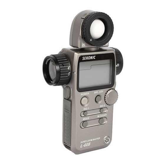
1. Parts Designation q Lumisphere UP/DOWN ring w Lumisphere ! 4 Lock lever e Liquid Crystal Display (LCD) @6 Zoom Lens Ring @ 4 Eyepiece @7 Zoom Lens Protective Glass r Average / Δ EV (Brightness Difference) button u Memory button t Set/change Dial !2 Power button (ON/OFF switch) -
Page 5: Explanation Of The Liquid Crystal Display (Lcd)
2. Explanation of the Liquid Crystal Display L-608 L-608CINE !0 q NOTE: For explanation purposes, the display illustrated here shows all icons and readouts simultaneously. Actual display will never show as above. Auto Electro-Luminescent Display (EL) In low light (EV 3 or less), a blue backlight will automatically illuminate the entire LCD. When using the Mini Light Receptor or a Booster (optional accessories) the LCD will be illuminated after measuring, regardless of the ambient light level. - Page 6 2. Explanation of the Liquid Crystal Display q Measuring Mode Icons Ambient (see page 13) Auto-Reset Cordless Flash (see page 19) Cord Flash (see page 18) Flash radio wave trigger mode (see page 35) w Incident / Reflected Spot Function Icons (see page 7) Lights when in Incident mode Lights when in Reflected Spot mode e ISO Display...
-
Page 7: Before Using
3. Before Using Attach the strap Attach the Strap @1 by passing the small end loop through the eyelet o and passing the other end of strap through it. WARNING • Please place in a location where an infant cannot reach and accidentally get the strap wrapped around his neck. -
Page 8: Replacing Battery During Measurement Or When Using The Memory Function
3. Before Using Replacing battery during measurement or when using the memory function Always turn the power OFF before replacing batteries. If batteries are removed with the power ON, measurements and settings in memory can no longer be recalled. If after replacing the battery, or during measurements, strange screens (displays that have not been set) appear in the LCD, or nothing happens, no matter what button is pushed, remove the battery and wait at least ten seconds and then replace the battery. -
Page 9: Mesurement Lock And Measurement Lock Off
3. Before Using Mesurement Lock and Measurement Lock Off 1. Hold down the Mode set button !0 and ISO1 button !1 and "LOC" will appear to indicate that the Measure- ment is locked. The last measurement is held until the lock is released, even if the Set/change dial is acci- dentally moved. -
Page 10: Basic Operation
4. Basic Operation Incident or reflected spot measuring To set for either incident or reflected light operation, turn the Incident / Reflected Spot Selector Switch @8 on the eye piece, to the desired position ( mark) until it clicks. Incident operation Reflected Spot operation When incident operation is selected, the mark will blink for three seconds and when Reflected... -
Page 11: Setting Measuring Mode
4. Basic Operation Setting measuring mode Hold down the Mode set button ! 0 and turn the Set/change dial t to select the desired mode. The mode switching sequence is shown in the chart below: MODE Shutter speed priority Radio Multiple Flash mode (Ambient light) (cumulative) mode See page 13... -
Page 12: Setting Dip Switches
4. Basic Operation Setting DIP Switches Switches for setting modes that are used infrequently are housed in the Battery compartment !9 of the meter. Select the mode you want prior to beginning measurements. The DIP switches can be set by sliding the DIP switch !8 for the mode you want to select in the ON position. -
Page 13: When Set For Incident Light
4. Basic Operation When set for incident light Measurement of incident light uses Lumisphere or recessed Lumisphere. You can switch between Lumisphere and recessed function by firmly rotating the Lumisphere UP/DOWN ring q until it clicks. Lumisphere Lumidisc When the Lumisphere is raised This is used to photograph people, buildings, and other three dimensional objects. -
Page 14: When Set For Reflected Light (Spot Metering)
4. Basic Operation When set for reflected light (spot metering) This method measures the brightness (luminance) of the light reflected from the subject. It is useful for distant objects such as landscapes, when you cannot go to the position of the subject, or for metering subjects that generate light (neon signs, etc.), highly reflective surfaces or translucent subjects (stained glass, etc.). -
Page 15: Basic Operation
4. Basic Operation < Lumigrid > (opsional) (Receiving Angle 54°) Remove the Lumisphere The lumisphere unit is removed by holding the upper and lower sections of upper and lower double Lumisphere up/down ring q and turning it in the counterclockwise direction while pushing the Lock lever upward. -
Page 16: Measurment
5. Measurement Measuring ambient light In this measurement mode, we have the choice of shutter priority mode, aperture priority mode and EV mode. Hold down the Mode set button !0 and turn the Set/change dial t to select ambient measurement mode 1-1 Shutter Speed Priority mode Hold down the Mode set button !0 and turn the Set/change dial t to select shutter Speed Priority... -
Page 17: Aperture Priority Mode
5. Measurement 1-2 Aperture Priority mode 1. Hold down the Mode set button ! 0 and turn the Set/change dial to select aperture priority mode. 2. Turn the Set/change dial t to set the desired f stop value. MODE Measured value (shutter speed) 3. -
Page 18: Ev Mode
5. Measurement 1-3 EV mode Open the Battery compartment cover !6 and slide the EV, DIP switch (see page 9) to the ON position. 1. Hold down the Mode set button !0 and turn the Set/change dial t to select EV value mode. MODE Shutter 2. -
Page 19: Cinematography
5. Measurement 1-4 Cinematography 1. Hold down the Mode set button ! 0 and turn the Set/ change dial t to select ambient light shutter speed priority mode. MODE 2. Turn the Set/change dial to select the Cine Speed for the camera that will be used. - Page 20 5. Measurement ☆ Example of correction value -1/3: Decrease ISO film speed by 1/3 stop, example: ISO 80 -1/3 stop = ISO 64 +1/3: Increase ISO film speed by 1/3 stop, example: ISO 80 +1/3 stop = ISO 100 Measured f stop 4.
-
Page 21: Measuring Flash Light
5. Measurement Measuring flash light This method of measurement can be done in the following modes; with cord, without cord, multiple flash with cord, multiple flash without cord and radio flash system (with optional radio transmitter module). When Measuring flash light, the shutter speed and F stop value (value combining ambient light and flash light: total amount of light) are displayed in the liquid crystal display and the ambient light and flash light are each displayed as separate values together with the total amount of light in the dot display. -
Page 22: Auto Reset Cordless Flash Mode
5. Measurement CAUTION: • There is danger of electric shock if the meter is handled with wet hands, during rain, in areas splashed by water or where there is a lot of moisture, if you use cord synchronized flash. • Under such conditions, it is recommended that you use the meter in the flash cordless mode or radio flash system (accessories), and keep the Synchro terminal cap in place. - Page 23 5. Measurement 3. When the Measuring button !5 is pressed, the mode mark will blink and the meter is ready to measure. The ready to measure mode will continue for approximately 90 seconds. During this time, fire the flash and make a measurement.
-
Page 24: Cord Multiple Flash (Cumulative) Mode
5. Measurement 2-3 Cord multiple flash (cumulative) mode These measurements are used when the light generated by the flash is inadequate for proper exposure. The repeated flash pops can be accumulated until the desired aperture is displayed. The cumulative number is infinite. Only one digit is displayed if the cumulative number is ten or more. -
Page 25: Cordless Flash (Cumulative) Mode
5. Measurement CAUTION: • There is danger of electric shock if the meter is handled with wet hands, during rain, in areas splashed by water or where there is a lot of moisture. Under such conditions, it is recommended that you use the meter in the flash cordless mode, and keep the Synchro terminal cap in place. - Page 26 5. Measurement 3. When the light from the flash is received, the measured value (f stop) is displayed. Each time this is repeated, the accumulated value for the aperture and the number of cumulative flashes is displayed. The ratio of flash element to the total amount of light 1/10 f stop...
-
Page 27: Advanced Functions
6. Advanced Functions Memory function This meter can store up to nine measured values in memory. This feature can be used in the follow- ing modes: ambient light (shutter speed priority, aperture priority and EV) flash (with, without cord and radio wave). Press the Measuring button !5 and take a measure- ment. -
Page 28: Averaging Function
6. Advanced Functions Averaging function This displays the average of two to nine of the values in memory. Press the Measuring button ! 5 and take a measurement. Press the Memory button u placing the measured value in memory. MEMORY When the Ave/ Δ... - Page 29 6. Advanced Functions Turn any secondary light source off. Point the Lumisphere toward the main light source, from the position of the subject and take a measurement. Press the Memory button u and store the value in memory. Press the Average/ ∆ EV button r and display the "A" mark on the LCD.
-
Page 30: How To Use An Incident Illuminance (Lux) Meter
6. Advanced Functions How to use an incident illuminance (LUX) meter Turn the Lumisphere UP/DOWN ring q to lower it to mark position. Make sure that componsating value (see page 29) is canceled ( Set the meter to EV mode (DIP switch 1) and ISO 100. Place meter parallel to the subject and take a measurement. -
Page 31: How To Use A Reflected Luminance (Cd/M ) Meter
6. Advanced Functions How to use a reflected luminance (cd/m ) meter Make sure that the componsating value (see page 29) is canceled ( Set the meter to EV mode (DIP switch 1) and ISO 100. Set meter for spot reading. Choose angle setting that is best suited for your subject. -
Page 32: How To Change The Compensating Function
6. Advanced Functions How to change the compensating function Exposure compensation can be made in precise 1/10 step increments in a +/- 9.9 EV range. Exposure compensation may be desired to match specific requirements, calibration to other light meters, or setting exposure calibration in 1 /10 steps up or down from standard ISO film speeds, It may also be desired when requiring compensation for filters, bellows extension, etc. -
Page 33: Use Of The Correction Indicator Function
6. Advanced Functions Use of the correction indicator function Set the measurement mode (incident light, reflected light) for the desired correction. It is possible to set the amount of correction independently for both incident and reflected light. It is not possible to switch between measurement modes (incident light, reflected light) if the setting is not completed. -
Page 34: Filter Setting
6. Advanced Functions Filter setting Filter settings (1) It is possible to set the correction of the film being used within a range of ±5 EV in 1/10 steps. The measurement corresponding to the set correction is displayed while pressing ISO2 button y. Select setting number 1 and item number 1 in the custom setting mode (refer to P34). -
Page 35: Analyzing Measurement Function
6. Advanced Functions Analyzing measurement function When measuring flash light, the shutter speed and F stop value (value combining ambient light and flash light: total amount of light) are displayed in the liquid crystal display and the ambient light and flash light are each displayed as separate values together with the total amount of light in the dot scale. -
Page 36: Custom Setting Function
6. Advanced Functions 10. Custom setting function It is possible to set the required functions in advance. CUSTOM SETTING LIST Item Model Lighting Custom Setting name Ambient & ISO 2 setting Film Filter Setting — — Flash Sensitivity 1/3 step 0.1EV step (±5EV) CINE... - Page 37 6. Advanced Functions To enter the custom setting mode, set power button ! 2 to the on position setting DIP switch 4 to on. It is not possible to enter the custom setting mode if DIP switch 4 is set to on after turning on the power.
-
Page 38: Radio Flash System
6. Advanced Functions 11. Radio flash system Setting the radio wave transmitter module (RT-32; optional) in the main unit and connecting the receiver RR-32 or RR-4; optional) to the flash provides a convenient system that enables one person working alone to measure flash light without a synchro cord, thereby making it possible to take measurements by triggering the flash from the exposure meter. - Page 39 6. Advanced Functions The set channel number will flicker on and off at this time. Turn the Set/change dial to set the channel setting. In the Setting mode, "ch" appears on the ISO indicator. At the same time, channel numbers (1 to 16 and 17 to 32) appear on the F indicator.
- Page 40 6. Advanced Functions Upon setting completion, the Radio flash mode is selected using the Set/change dial while the mode button is depressed. Confirm that the unit and the radio wave receiver are set to the same channel number. The flash unit will fire when the measurement button of the unit is pressed and measurements can be made at the same time.
-
Page 41: Accessories
7. Accessories Mini Light Receptor (Sold separately) • Incident light receiving unit with a compact 12mm diameter light receiving surface. • For measuring narrow areas used for photographing small subjects or copy work. Booster (Sold separately) • For light measuring on camera ground glass, focusing screens, SLR eyepieces, microscope eyepiece. -
Page 42: Accessories
7. Accessories Radio flash system (Sold separately) • Combining radio wave transmitter module (RT-32) with radio wave receiver (RR-32 or RR-4) enables measurements by triggering the flash from the exposure meter. Radio wave transmitter module (RT-32) Radio wave receiver Radio wave receiver (RR-32) (RR-4) •... -
Page 43: Technical Data
8. Technical Da ta ・Type : Digital exposure meter for ambient and flash meter ・Light receiving method : Incident light and reflected Incident light : Convertible to flat diffuser (Lumisphere in down position) Reflected light : 1° to 4° element Zoom (display in finder) Metering distance 1m ~ ∞... - Page 44 8. Technical Data Shutter opening angle (608 Cine only) : 5° ~ 270° (in steps), others: 144°, 172° Filter correction (608 Cine only) : 85-, n3-, n6-, n9-, A3-, A6-, A9- ・Other features All-weather feature : JIS standard water resistance class 4, splash-proof type Memory function : 9 readings Memory clear・recall function...
-
Page 45: Safety Guide
9. Safety Guide WARNING: • Please keep in a location where an infant cannot reach and accidentally get the strap wrapped around his neck. There is danger of strangulation. • Never place batteries in fire, short, disassemble, or heat them. The batteries might break down, and cause injury or pollute the environment. -
Page 46: Care And Maintenance
Do not attempt to remove the rubber seal of the battery compartment cover. • If the rubber seal’s surface is damaged,water or moisture may enter and damage the meter. If this has happened, you must send your meter to the Sekonic Sevice Center in your country. - Page 47 FCC & IC compliance information: Warning: Changes or modifications to this unit not expressly approved by the party responsible for compliance could void the user's authority to operate the equipment. Note: This equipment has been tested and found to comply with the limits for a Class B digital device, pursuant To Part 15 of the FCC Rules.