Table of Contents

Related Manuals for E-FLITE BAe Hawk 15 DF


Summary of Contents for E-FLITE BAe Hawk 15 DF
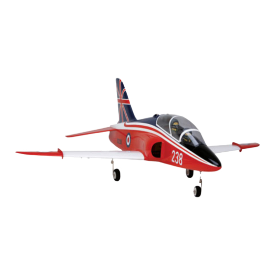
- Page 1 BAe Hawk 15 DF Assembly Manual Specifications Wingspan: 33 in (846mm) Length: 35.4 in (381mm) Wing Area: 206 sq in (13.2 sq dm) Weight w/o Battery: 34–36 oz (964–1021 g) Weight w/Battery: 43–46 oz (1219–1304 g) Pilots not included (PKZ4414)
-
Page 2: Table Of Contents
Optional Accessories ..........3 a right or left wing panel, two servos, etc. E-flite’s BAe Hawk 15 DF ARF is a sport scale version Required Brushless Ducted Fan Setup ....... 3 of the British trainer. Constructed of fiberglass and Remember to take your time and follow the directions. -
Page 3: Recommended Radio Equipment
™ DX6i 2.4GHz DSM ® 6-channel system. If follow the manufacturer’s instructions when Paper towels Pencil using your own transmitter, we recommend the E-flite disposing of Lithium Polymer batteries. ® Pin drill Rubbing alcohol S75 Super Sub-Micro servos . Ruler... -
Page 4: Fan Installation
2. Slide the thrust tube onto the fan assembly and over the motor wires. fuselage former. The wires will be on the side of the center line former that is away from the opening as shown. E-flite BAe Hawk ARF Assembly Manual... - Page 5 9. Slide the fan assembly as far forward in the fuselage as possible without damaging the fan assembly or fuselage. The front edge of the fan assembly will fit snugly into the fan intake inside the fuselage. E-flite BAe Hawk ARF Assembly Manual...
-
Page 6: Aileron Servo Installation
DO NOT remove the string from the wing. The string will be used to pull the aileron servo lead through the wing later in this section. E-flite BAe Hawk ARF Assembly Manual... - Page 7 10. Repeat Steps 1 through 9 to install the remaining aileron servo. Use care when installing the servo mounting strap. Over-tightening the strap could stress the wing sheeting and even push the servo through the top of the wing. E-flite BAe Hawk ARF Assembly Manual...
-
Page 8: Aileron Linkage Installation
Use low-tack tape to tape the aileron in position so it doesn’t move during the linkage installation. This will make the procedure go easier and will help in keeping things aligned during the linkage installation process. E-flite BAe Hawk ARF Assembly Manual... - Page 9 Use a paper towel and rubbing alcohol to remove the lines from the aileron once the covering has been removed. E-flite BAe Hawk ARF Assembly Manual...
- Page 10 15. Use hobby scissors to trim the aileron control pushrod wire. horn servo cover on the lines that are molded into it. Use medium grit sandpaper to clean up and rough edges and to round the corners slightly on the cover. E-flite BAe Hawk ARF Assembly Manual...
-
Page 11: Mounting The Main Wing Panels
You can also use large heat shrink to secure the extension to the servo lead. Be careful not to get the heat shrink too hot as it could distort the plug. E-flite BAe Hawk ARF Assembly Manual... - Page 12 You can use low-tack tape to make an outline about a 1/16-inch (1.5mm) inside the wing outline on the fuselage to prevent it from scratching the paint. E-flite BAe Hawk ARF Assembly Manual...
-
Page 13: Stabilizer Installation
Not doing remaining wing panel to the fuselage. so may result in the jig being crooked and could produce the wrong angle when gluing the stabilizer halves together. E-flite BAe Hawk ARF Assembly Manual... - Page 14 3. Remove the elevators from the stabilizer halves. Use a hobby knife w/#11 blade to remove the covering from the end of both the left and right stabilizers. E-flite BAe Hawk ARF Assembly Manual...
- Page 15 Both measurements must be equal. If the edges of each stabilizer half. they are not, reposition the stabilizer and re-measure until both measurements are equal on both sides of the fuselage. E-flite BAe Hawk ARF Assembly Manual...
- Page 16 (with a new blade) or a soldering before gluing the stabilizer in position. iron for cutting the covering. These will melt the covering and lower the chances of cutting into the wood structure of the stabilizer. E-flite BAe Hawk ARF Assembly Manual...
-
Page 17: Elevator Installation
Remove any excess epoxy using a paper 6. Slide the two hinges into the slots that have been towel and rubbing alcohol. Use low-tack tape to pre-cut into the elevator. hold the wire tightly in position in the elevator. E-flite BAe Hawk ARF Assembly Manual... - Page 18 12. Once the CA has fully cured, lightly pull on the elevator and stabilizer to make sure the hinges are secure. If not, apply additional CA to the hinges that are not secure. E-flite BAe Hawk ARF Assembly Manual...
-
Page 19: Elevator Linkage Installation
2. Tack the pushrod into position on the former with medium CA as you might need to break it loose if maintenance is required to the fan and motor. 14. Repeat Steps 5 through 13 to install the remaining elevator. E-flite BAe Hawk ARF Assembly Manual... - Page 20 1/4-inch (6mm) from the end of the wire. wire into the hole in the elevator control horn. Use the pushrod keeper to secure the wire to the elevator control horn. E-flite BAe Hawk ARF Assembly Manual...
-
Page 21: Landing Gear Installation
4. Repeat Steps 1 through 3 to install the remaining main gear wire and wheel. Always use threadlock on metal-to-metal fasteners to prevent them from vibrating loose. E-flite BAe Hawk ARF Assembly Manual... - Page 22 Check to make sure the nose gear wire can move freely so the steering servo is not overloaded when trying to steer your aircraft. E-flite BAe Hawk ARF Assembly Manual...
-
Page 23: Nose Gear And Elevator Servo Installation
Use dental floss to secure the for the servo mounting screws. connectors together. Use a #0 Phillips screwdriver to remove the servo arm from the servo. E-flite BAe Hawk ARF Assembly Manual... - Page 24 2mm washers to take up the excess space before installing the nut. The nut should bottom out on the threads and be tight so it will not come loose. E-flite BAe Hawk ARF Assembly Manual...
-
Page 25: Speed Control And Receiver Installation
Check to make sure the nose gear wire can move freely so the steering servo is not overloaded when trying to steer your aircraft. E-flite BAe Hawk ARF Assembly Manual... -
Page 26: Canopy Installation
Never cut the antenna wire as it can greatly reduce the range of your radio system. 5. When installing a remote receiver, attach it as shown in the fuselage using hook and loop tape. E-flite BAe Hawk ARF Assembly Manual... - Page 27 3. Slide a rubber band through the eye hook as Insert the pins from the front of the canopy into shown in the photo. the holes in the fuselage, and the rubber band will hold the canopy secure on the fuselage. E-flite BAe Hawk ARF Assembly Manual...
-
Page 28: Thrust Tube Installation
fan assembly. It will also fit flush with the end of the fuselage when positioned correctly. Use the clear tape supplied with your aircraft to tape the thrust tube to the fan housing. E-flite BAe Hawk ARF Assembly Manual... -
Page 29: Motor Battery Installation
You may have to remove the excess part of the servo arm on the elevator and the steering servo for clearance of the main battery. 2. Slide the strap through the slots in the battery/radio tray as shown. E-flite BAe Hawk ARF Assembly Manual... -
Page 30: Control Throws
Use a black felt-tip marker to detail the front opening of the intake to add realism to your model. E-flite BAe Hawk ARF Assembly Manual... -
Page 31: Center Of Gravity
Replace any items that would be considered questionable. Failure of any of these components in flight would mean the loss of your aircraft. E-flite BAe Hawk ARF Assembly Manual... -
Page 32: Range Test Your Radio
Happy Landings! Warranty Period Horizon Hobby, Inc., (Horizon) warranties that the Products purchased (the “Product”) will be free from defects in materials and workmanship at the date of purchase by the Purchaser. E-flite BAe Hawk ARF Assembly Manual... - Page 33 Provided warranty conditions have been met, your Product will be repaired or replaced free of charge. Repair or replacement decisions are at the sole discretion of Horizon Hobby. E-flite BAe Hawk ARF Assembly Manual...
-
Page 34: Instructions For Disposal Of Weee By Users In The European Union
Horizon Hobby UK Units 1-4, Ployters Road Staple Tye Harlow, Essex CM187NS United Kingdom Horizon Technischer Service Otto-Hahn-Str. 9a 25337 Elmshorn Germany E-flite BAe Hawk ARF Assembly Manual... -
Page 35: 2008 Official Academy Of Model Aeronautics Safety Code
National Model Rocketry Safety Code; however, use agreement between sites, or testing which they may not be launched from model aircraft. determines that no interference exists. A frequency- Officially designated AMAAir Show Teams (AST) E-flite BAe Hawk ARF Assembly Manual... - Page 36 © 2008 Horizon Hobby, Inc. 4105 Fieldstone Road Champaign, Illinois 61822 (877) 504-0233 horizonhobby.com E-fliteRC.com 13276...