AMX NX-1200 Webconsole And Programming Manual
Nx-series controllers, enova dvx all-in-one presentation / digital media switchers, massio controlpads
Hide thumbs
Also See for NX-1200:
- Hardware reference manual (42 pages) ,
- Hardware reference manual (43 pages) ,
- Hardware reference manual (48 pages)
Table of Contents
Advertisement
WE B CO N S O LE A N D P RO G RA M M IN G G UI DE
N X - S E R I ES C O N T RO L LE RS
®
E N OVA
DVX A L L - I N - O N E P RES E N T AT I O N SW I TC H E RS
®
E N OVA
D GX DI G I T A L M EDIA SW I TC H E RS
™
M ASS I O
C O N T RO LPAD S
NX -1 20 0, N X- 220 0, N X- 320 0, N X-4 200
DVX-3250HD-SP , DVX-3250HD-T, DVX-3255HD-SP , DVX-3255HD-T, DVX-3256HD-SP, DVX-3256HD-T
DVX-2250HD-SP , DVX-2250HD-T, DVX-2255HD-SP , DVX-2255HD-T, DVX-2210HD-SP, DVX-2210HD-T
DGX8-ENC, DGX16-ENC, DGX32- EN C- A, DGX64-ENC
MCP- 10 6, MCP- 10 8
Advertisement
Table of Contents

Related Manuals for AMX NX-1200


Summary of Contents for AMX NX-1200
- Page 1 WE B CO N S O LE A N D P RO G RA M M IN G G UI DE N X - S E R I ES C O N T RO L LE RS ® E N OVA DVX A L L - I N - O N E P RES E N T AT I O N SW I TC H E RS ®...
- Page 2 COPYRIGHT NOTICE AMX© 2015, all rights reserved. No part of this publication may be reproduced, stored in a retrieval system, or transmitted, in any form or by any means, electronic, mechanical, photocopying, recording, or otherwise, without the prior written permission of AMX. Copyright protection claimed...
-
Page 3: Table Of Contents
Enova DVX ............................. 28 Before You Start ......................29 Verifying the Current Firmware Version ................. 29 Downloading the Latest Firmware Files from www.amx.com ......... 29 NetLinx Integrated Controllers ......................29 Master and Device Firmware Kit Files for NX-Series Controllers ............... 29 Downloading NX-Series Controller Firmware Files on www.amx.com............... - Page 4 Table of Contents Downloading Enova DVX Firmware Files on www.amx.com................30 Master and Device Firmware Kit Files for Massio ControlPads ............31 Required Order of Firmware Updates ................31 Required Order of Firmware Updates for DVX Controllers ..............31 Upgrading Firmware via USB ..................31 Upgrading Firmware via NetLinx Studio ................
- Page 5 Table of Contents Locking/Disabling a Role ........................50 Security - Users ......................51 Default User Accounts .......................... 51 Adding a New User..........................52 Viewing and Editing User Security Settings ..................53 Deleting a User ............................. 53 Locking/Disabling a User........................53 Security Settings - LDAP....................
- Page 6 Table of Contents Switch Mode............................69 Configuring/Switching the Downmix Signal ..................70 Designating an Input for Downmixing (from Configuration page) ............70 Configuration Page......................71 Configuration Components ........................71 Video Settings............................73 Inputs Only ................................. 73 Outputs Only ............................... 73 DXLink Video Settings...........................
- Page 7 Table of Contents CHARD..................................... 88 CHARDM....................................88 CLEAR FAULT ..................................88 CTSPSH ....................................88 CTSPSH OFF .................................... 88 GET BAUD ....................................89 GET FAULT ....................................89 GET STATUS.................................... 89 HSOFF ..................................... 89 HSON....................................... 89 RXCLR ..................................... 89 RXOFF ..................................... 89 RXON .......................................
- Page 8 Table of Contents PoE SEND_COMMANDs ....................100 GET CLASS ................................... 100 GET CURRENT ..................................100 GET FAULT ................................... 100 GET STATUS..................................100 GET VOLTAGE..................................100 SET FAULT DETECT OFF ............................... 100 SET FAULT DETECT ON................................. 100 SET POWER OFF ................................... 100 SET POWER ON..................................
- Page 9 Table of Contents GET PLATFORM INFO ................................107 HELP SECURITY ................................... 107 ICSPMON ENABLED|DISABLED [PORT]..........................107 IMPORT CONFIG .................................. 107 IMPORT IRL..................................107 IMPORT KIT ..................................107 IMPORT TKN ..................................108 IP STATUS ................................... 108 IPDD ..................................... 108 JAVA SECURITY ................................... 108 LIST AUDIT FILES ................................
- Page 10 Table of Contents SHOW AUDIT [FILENAME] ..............................116 SHOW AUDIT LOG ................................116 SHOW BUFFERS ................................... 116 SHOW COMBINE................................... 116 SHOW DEVICE <D:P:S> ................................ 117 SHOW HTTPS REDIRECT ..............................117 SHOW LOG.................................... 117 SHOW MAX BUFFERS ................................118 SHOW MEM ..................................118 SHOW NOTIFY ..................................
- Page 11 Table of Contents Changes to LDAP Implementation (v1.5.x)..............130 User Query Attribute........................... 130 FTP Access with LDAP Authentication ....................130 SSH Access with LDAP Authentication ....................130 Assumptions and Prerequisites ................... 131 Example - Setting Up User's Access Rights ..............132 Administrator Access Example......................
- Page 12 Table of Contents CLKMGR_GET_END_DAYLIGHTSAVINGS_RULE() ........................ 144 CLKMGR_SET_END_DAYLIGHTSAVINGS_RULE(CONSTANT CHAR RECORD[])..............144 NX-Series Controllers - WebConsole & Programming Guide...
-
Page 13: Overview
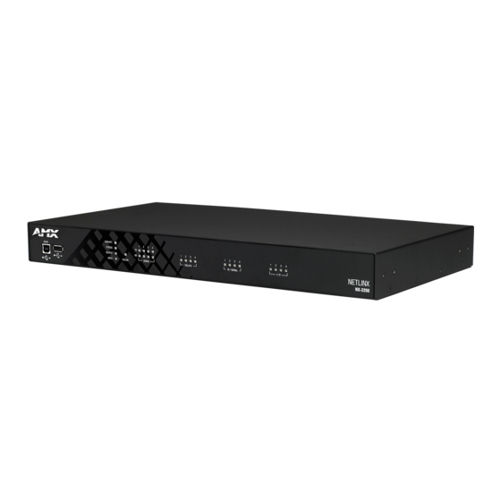
NX-4200 NetLinx NX Integrated Controller NOTE: Refer to the Products > Central Controllers > NetLinx NX Integrated Controllers page at www.amx.com for details and variations available for these products. NX controllers feature an on-board Web Console which allows you to connect to the NX controller via a web browser and make various configuration and security settings. -
Page 14: Enova Dgx Digital Media Switchers
Enova DGX 16 Enclosure DGX32-ENC-A Enova DGX 32 Enclosure DGX64-ENC Enova DGX 64 Enclosure NOTE: Refer to the Products > Digital Media Switchers page at www.amx.com for details and variations available for these products. ™ Massio ControlPads Massio ControlPads Name... -
Page 15: Cpu Usage
Overview The code in PRGM EX. 1 would be better implemented using a timeline, as illustrated in PRGM EX. 2: DEFINE_CONSTANTS LONG FEEDBACK_TIMES[1] = {500} INTEGER FEEDBACK_TIMELINE = 1 DEFINE_START TIMELINE_CREATE(FEEDBACK_TIMELINE, FEEDBACK_TIMES, 1, TIMELINE_RELATIVE, TIMELINE_REPEAT) DEFINE_EVENT TIMELINE_EVENT[FEEDBACK_TIMELINE] [dvTP,1] = [dvDev,1] [dvTP,2] = value1 [dvTP,3] = ![dvTP,3] PRGM EX. - Page 16 Overview These statistics indicate how many times mainline has been executed and why it has been executed. Repeatedly executing “show interp stats” will give you an idea which code construct is causing mainline to execute. For example, if a variable is being changed, you will see the “Variable Change”...
-
Page 17: Quick Setup And Configuration Overview
Set the boot-time operations on the rear Configuration DIP switch. (The DIP switch is located on the front panel of the NX-1200.) Connect and communicate with the on-board Master via the Program port. Set the System Value being used with the on-board Master. - Page 18 Overview In the Workspace area, right-click and select Refresh Zero Conf ig List. The controller appears in the list of devices as shown in FIG. 2: Workspace bar (Zero-Config tab selected) FIG. 2 Double-click the Master you want to access it in the WebConsole. Accessing the Master requires valid login information.
-
Page 19: Initial Configuration
NetLinx Studio is available to download from www.amx.com. Login to download the latest version. Alternatively, if it is already installed, use the Web Update option in NetLinx Studio’s Help menu to obtain the latest version. The default location for the NetLinx Studio application is Start > Programs > AMX Control Disc > NetLinx Studio > NetLinx Studio. - Page 20 Initial Configuration Click the System Settings button to open the Communications Settings dialog (FIG. 5). If there is no system selected, click the Default Settings button to open the dialog. Communication Settings dialog - Recent tab FIG. 5 Select the USB tab to view the USB options (FIG. 6). Communications Settings dialog - USB tab FIG.
-
Page 21: Configuring The Nx Controller For Lan Communication
Initial Configuration Right-click the Online Tree tab entry and select Refresh System: the Controller should appear in the Device Tree (FIG. 7): Workspace Bar - Online Tree FIG. 7 NOTE: If the Master does not appear in the list, verify that the USB cable is connected properly. Once USB communication has been established, use NetLinx Studio to configure the Controller for LAN Communication, as described in the next section. - Page 22 Initial Configuration Click Get IP Information to enable the fields for editing (FIG. 9): Network Addresses dialog showing initial IP information FIG. 9 Enter the System, Device (0 for NetLinx Masters), and Host Name information. NOTE: Host names may contain only the ASCII letters 'a' through 'z' (in a case-insensitive manner), the digits '0' through '9', and the hyphen ('-').
-
Page 23: Obtaining The Nx Controller's Ip Address (Using Dhcp)
Initial Configuration Repeat steps 1 - 5 from the previous section, but rather than selecting the USB tab, select Network and edit the settings to match the IP address you are using (Static or Dynamic). If you want the Master to require authentication for access, enter a User Name and Password in the provided fields to secure the Master. -
Page 24: Assigning A Static Ip To The Nx Controller
Initial Configuration Assigning a Static IP to the NX Controller NOTE: Verify there is an active LAN connection on the LAN port of the Master before beginning these procedures. In NetLinx Studio, select Diagnostics > Network Addresses to open the Network Addresses dialog (FIG. 13): NetLinx Studio: Network Addresses dialog FIG. -
Page 25: Communicating Via Ip Address
Initial Configuration Communicating via IP Address Whether the on-board Master’s IP address was set or obtained via DHCP, use the IP address information from the Network Addresses dialog to establish communication via the LAN-connected Master. Use NetLinx Studio to obtain the IP address of the NX controller. If you do not have an IP address, follow the steps outlined in either the Obtaining the NX Controller’s IP Address (using DHCP) section on page 23, or the Assigning a Static IP to the NX Controller section on page 24. - Page 26 Initial Configuration Select the Network tab (FIG. 17). Communications Settings dialog - Network tab FIG. 17 Click New to open the New TCP/IP Setting dialog. In this dialog, you can enter both a previously obtained DHCP or static IP address and an associated Description for the connection into their respective fields. (FIG. 18): NetLinx Studio - New TCP/IP Setting dialog FIG.
- Page 27 Initial Configuration Click OK to save your newly entered information and close the Communication Settings dialog and return to the Communication Settings dialog. Note the selected IP address is indicated in the Conf iguration field (FIG. 20): NetLinx Studio - Communication Settings dialog (Current Master Connection field indicating the selected IP address) FIG.
-
Page 28: Upgrading Firmware
The basic process of upgrading firmware on NX-series controllers involves downloading the latest firmware files from www.amx.com and using NetLinx Studio to transfer the files to a target NX controller. Use the OnLine Device tree in NetLinx Studio to view the firmware files currently loaded on the Central Controller. FIG. 21 shows an... -
Page 29: Before You Start
NetLinx Studio is available to download from www.amx.com. Login to download the latest version. Alternatively, if it is already installed, use the Web Update option in NetLinx Studio’s Help menu to obtain the latest version. The default location for the NetLinx Studio application is Start > Programs > AMX Control Disc > NetLinx Studio > NetLinx Studio. -
Page 30: Downloading Nx-Series Controller Firmware Files On Www.amx.com
Downloading NX-Series Controller Firmware Files on www.amx.com Visit the appropriate product page on www.amx.com for the latest NX Master and Device Controller firmware (*.kit) files for your NX controller. Firmware file links are available along the right-side of the catalog page (FIG. 22): www.amx.com - sample NX Controller Firmware File links... -
Page 31: Master And Device Firmware Kit Files For Massio Controlpads
Upgrading Firmware Master and Device Firmware Kit Files for Massio ControlPads Below is a table outlining the Master and Device Firmware (*.kit) files used by Massio ControlPads: Master and Device Firmware Files for Massio ControlPads MCP-106/108 Master Firmware: SW2102_MCP_10x_vx_x_xxx.kit Device Firmware: SW2102_MCP_10x_Device_vx_xx_x.kit HTTP Firmware Kit: SW2102_MCP_10x_vx_x_xxx-http.kit NOTE: The HTTP f irmware kit enables you to upgrade f irmware via an HTTP server. - Page 32 Upgrading Firmware Click the Browse button (...) to locate and select the firmware (*.kit) file that will be transferred, in the Browse for Folders dialog (FIG. 25): NetLinx Studio - Send to NetLinx Device dialog FIG. 25 The selected file is indicated in the Files window. Verify the target’s System number matches the value listed within the active System folder in the OnLine Tree.
-
Page 33: Resetting The Factory Default System And Device Values
Upgrading Firmware Once the process is complete, you can upgrade the remaining firmware files. All device files must be kept at compatible firmware versions for proper operation. Therefore, all files should be used when upgrading any firmware associated with the Integrated Controllers. -
Page 34: On-Board Webconsole User Interface
On-Board WebConsole User Interface On-Board WebConsole User Interface WebConsole UI Overview NetLinx Masters have a built-in System Configuration interface that allows you to make various configuration settings via a web browser on any PC that has access to the Master. The System Configuration interface (an on-board web configuration) contains a comprehensive set of web pages that can be used during setup to manage your system’s network, security, and system needs, as well as configure its inputs and outputs while executing switches (FIG. -
Page 35: Accessing The Webconsole
On-Board WebConsole User Interface Accessing the WebConsole From any PC that has access to the LAN that the target Master resides on: Open a web browser and type the IP Address of the target Master in the Address Bar. Press Enter to access WebConsole for that Master. The initial view is the Web Control page (FIG. 28). When using the Microsoft Internet Explorer browser in Windows 8, you may not be able to login and connect to the Master via the WebConsole. -
Page 36: Webconsole - Network Options
WebConsole - Network Options WebConsole - Network Options Network Overview The Network page (FIG. 30) is accessed by clicking Network on the page’s main heading. This page allows you to view and configure various aspects of the Master’s network: IPv4 Setup - Options on this page allow you to view/change the Master’s IP and DNS address information. See the Network ... -
Page 37: Network - Ipv4 Setup
WebConsole - Network Options Network - IPv4 Setup Click IPv4 Setup to access the IPv4 page (FIG. 31) and view and configure IP and DNS addresses for the Master. Use the options on this page to view/edit the Master’s network settings. A user can only modify the information on this page if it is assigned a Role that includes the Network Configuration permission. -
Page 38: Network - Ipv6 Setup
WebConsole - Network Options Network - IPv6 Setup Click IPv6 Setup to access the IPv6 page (FIG. 32) and view the IPv6 address, subnet mask, and gateway for the Master. This information is view-only. Network - IPv6 Setup page FIG. 32 Network - Date/Time Click the Date/Time link (on the Network page) to access the Date/Time page (FIG. -
Page 39: Setting The Mode For The Clock Manager
WebConsole - Network Options Setting the Mode for the Clock Manager In the Manage System tab (FIG. 33), select a Time Sync option. Network Time: This option allows the Master to manage it’s clock by connecting to a NIST (Internet Time Service) Server. ... -
Page 40: Adding A Custom Nist Server To The List
WebConsole - Network Options Adding a Custom NIST Server to the List Click Add Server. The Add New Server dialog opens (FIG. 36). Add New Server dialog FIG. 36 In the New Server URL field, enter the URL of the NIST Server. The URL is used only to help you manage entries, and is not verified or used internally by the clock manager. -
Page 41: Webconsole - Security Options
NOTE: This user name and password information is also used by both G5 touch panels (within the System Connection f irmware page) and AMX software applications such as NetLinx Studio v 4.0 and above to communicate securely with a Master using encrypted communication. -
Page 42: User And Role Name Rules
WebConsole - Security Options User and Role Name Rules User account and role names must follow these rules: Case-sensitive Must be between 4 and 20 alpha-numeric characters: A-Z, a-z, 0-9 The following characters are allowed: - _ . # and <space>. ... -
Page 43: Security - General
WebConsole - Security Options Security - General The General Security Settings page provides global permissions for various options that may be individually selected and applied to all users. The Master provides 3 levels of security settings presets: Low, Medium, and High. The levels are simply presets of various security settings. - Page 44 WebConsole - Security Options System Security Options (Cont.) Option Description Password Expiration Select to force a user to change its password after a set period of time. After enabling the password expiration options, use the spin box to set the interval for password expiration. You can set an amount of time in the range of 1 to 180 days.
-
Page 45: Security Presets
Select to require user name and password authentication on devices connected to the LAN ports on the Master. Devices On LAN Ports LAN AMX Device Select to allow ICSP access to the Master for Device-type users connected to the LAN ports. Expand the LAN AMX Connection Device Connection section to view this option. -
Page 46: Audit Logs
WebConsole - Security Options Audit Logs An audit log includes the date/time of the event, the event type, the software or hardware component where the event occurred, the source of the event, the subject identity, and the outcome of the event. For events related to a remote device, the audit log includes the source and destination network addresses and ports or protocol identifiers. -
Page 47: Security - Roles
WebConsole - Security Options Security - Roles A Role is a set of privileges or permissions assigned to one or more users. The privileges and permissions can involve various functions or allow access to specific ports. Any privileges or permissions set for a role are inherited by all users sharing that role. Multiple roles can be assigned to a user, but at the same time, roles are not required for users. -
Page 48: Role Permissions
WebConsole - Security Options Role Permissions The following table lists the permissions available for Roles: Role Permissions Option Description Audit Log Select to allow the role to view and configure the audit log. Device Select to allow the role to modify the configuration of NetLinx and 3rd party devices including the following: Configuration •... -
Page 49: Adding A New Role
WebConsole - Security Options Role Permissions (Cont.) Option Description User Access 1-4 Select to allow the role access generic access permissions. These privileges are to be used by NetLinx programs. User Management Select to allow the role to view, create, modify, lock, and remove user accounts. NOTE: A user has the ability to change its own password, regardless of whether it has the User Management permission. -
Page 50: Viewing And Modifying Role Security Settings Details
WebConsole - Security Options Viewing and Modifying Role Security Settings Details Click any Role listed on the Role Security Details page to expand the view to show details for the selected user Role (FIG. 41): Lock button Click to expand Edit button Role Security Details Page FIG. -
Page 51: Security - Users
WebConsole - Security Options Security - Users Select the Users option on the Security Page to access the User Security Details page (FIG. 42). The options on this page allow authorized users to add/delete/lock User accounts and configure User’s access rights. Locking a user account disables the account without deleting it. -
Page 52: Adding A New User
WebConsole - Security Options Adding a New User TIP: For a quicker conf iguration, it is recommended to def ine all roles and permissions before def ining users. Select the Users option (in the Security section) to view the User Security Details page. Click the Add User button (see FIG. -
Page 53: Viewing And Editing User Security Settings
WebConsole - Security Options Viewing and Editing User Security Settings Click any User listed in the User Security Details page to view the security settings for the selected User (FIG. 44): Edit button click to expand Lock button Security - Users page FIG. -
Page 54: Security Settings - Ldap
DN. User Query Attr This LDAP attribute is used for the AMX equipment user search (for example, UID). NOTE: This attribute MUST be unique in the context of the LDAP BASEDN or the search will fail. -
Page 55: Accepting Changes
WebConsole - Security Options If an administrator password change is desired, LDAP must be disabled, the password changed and saved and then LDAP re- enabled. Users may not be added or deleted via the web pages when LDAP is enabled. ... -
Page 56: Security - Profile
WebConsole - Security Options Security - Prof ile The Profile page (FIG. 46) enables a user to see its own roles and permissions, and to change its password. The user cannot change the roles and permissions on this page. Security - Profile page FIG. -
Page 57: Webconsole - System Options
WebConsole - System Options WebConsole - System Options System Overview The System page is accessed by clicking System on the page’s main heading. This page allows you to view and configure various aspects of the NetLinx System: System Information - Options on this page allow you to view a detailed list of the properties of the Master. See the System ... -
Page 58: System - Devices
WebConsole - System Options System - Devices The Devices page (FIG. 49) contains information about the Master and any connected devices. Select a device from the Device List and its information appears in the Device Information area. The information in this area is view-only, unless the device allows a change to its device number. -
Page 59: Webconsole - Modules Options
WebConsole - Modules Options WebConsole - Modules Options Modules Overview The Modules page is accessed by clicking Modules on the page’s main heading. This page allows you to view and configure various aspects of the NetLinx System: Device Options - Options on this page display various details specific to additional (non-NetLinx) System Devices. See the ... -
Page 60: Modules - Device Options
WebConsole - Modules Options Modules - Device Options Click the Device Options link (in the Manage Devices tab) to access the Details for Additional Devices page (FIG. 50). The options on this page display various details specific to additional (non-NetLinx) System Devices. Conf iguring Device Binding Options Use the Conf igure System Binding Options to specify how the Master will manage Bound Devices: Conf igure System Binding Options... -
Page 61: Modules - Bindings
WebConsole - Modules Options Modules - Bindings Click Bindings to access the Device Bindings page (FIG. 51). Use the options on this page to configure application-defined Duet virtual devices with discovered physical devices. Modules - Bindings FIG. 51 The table on this page displays a list of all application-defined devices, including each device’s "Friendly Name", the Duet virtual device’s D:P:S assignment, the associated Duet Device SDK class (indicating the type of the device), and the physical device’s D:P:S assignment. -
Page 62: Configuring Application-Defined Devices
WebConsole - Modules Options Conf iguring Application-Def ined Devices Elements such as DUET_DEV_TYPE_DISPLAY and DUET_DEV_POLLED are defined within the NetLinx.axi file. The NetLinx.axi file contains both the new API definitions, as well as the pre-defined constants that are used as some of the API arguments (ex: DUET_DEV_TYPE_DISPLAY). -
Page 63: Application Devices And Association Status
WebConsole - Modules Options Application Devices and Association Status There are two types of application devices: Static Bound application devices and Dynamic application devices: Static Bound application devices specify both a Duet virtual device and its associated Device SDK class type, as well as a ... -
Page 64: Modules - User-Defined Devices
WebConsole - Modules Options Modules - User-Def ined Devices Click the User-Def ined Devices link (in the Manage Devices tab) to access the User-Def ined Devices page (FIG. 53). This page provides a listing with all of the dynamic devices that have been discovered in the system, and allows you to add and delete User-Defined Devices. -
Page 65: Modules - Active Devices
WebConsole - Modules Options SDK Class Types Amplifier Digital Video Recorder MultiWindow Text Keypad AudioConferencer Disc Device PoolSpa AudioMixer Display PreAmp Surround Sound Processor AudioProcessor Document Camera Receiver Utility AudioTape HVAC RelayDevice AudioTunerDevice IODevice RFID System Video Conferencer Camera Keypad Security System Video Processor Digital Media Decoder... -
Page 66: Viewing Physical Device Properties
WebConsole - Modules Options Viewing Physical Device Properties Hold the mouse cursor over the Device entry in the table to display detailed device properties for that device, in a pop-up window (FIG. 56). Active Devices - Device Properties pop-up FIG. 56 NX-Series Controllers - WebConsole &... -
Page 67: Webconsole - Switching Options
WebConsole - Switching Options WebConsole - Switching Options Switching Overview The Switching page is used to route the system’s inputs to its outputs during system setup. Each input and output can be labeled by filling in the Input Name or Output Name field on the Configuration page. The one exception to this statement is the audio input “Downmix”... -
Page 68: Switching Page Components
WebConsole - Switching Options Switching Page Components The Switching page features the following components (labeled alphabetically to correspond to FIG. 57 on previous page): Auto Take button (default is unselected) – when checked, this button persists the Auto Take function and remains illuminated until unchecked. -
Page 69: Switch Mode
WebConsole - Switching Options Group Restore to Default button – click to open the Warning dialog box below, which requires you to select an A/V Group and an I/O Group to restore to their factory default settings. Switch Mode The Switch Mode buttons allow you to choose between switching Audio follow Video (A/V), Video (with embedded audio), or Audio only. -
Page 70: Configuring/Switching The Downmix Signal
WebConsole - Switching Options Conf iguring/Switching the Downmix Signal When the system contains Audio Switching Boards, one embedded audio signal** can be downmixed and routed at any given time. ** Signal must be Dolby, TrueHD, Dolby Digital, DTS-HD Master Audio, DTS, or 2 CH through 8 CH L-PCM. When Audio Switch Mode is selected, the “Downmix”... -
Page 71: Configuration Page
WebConsole - Switching Options Conf iguration Page The Configuration page is used to configure inputs and outputs in the system. The most recently selected input or output displays in the Configuration page in accordance with the currently selected Config Viewer button (Recent, Inputs Only, or Outputs Only). The Configuration page displays the Switching page components compressed on the left. - Page 72 WebConsole - Switching Options Restore to Default (red) button – click to open the Warning dialog box below, which requires you to select the Yes button to restore the currently selected input or output to its factory default settings. Video Details or Audio Details button – click to display additional video or audio details for inputs or outputs, depending on current selection (video: colorSpace, flags, pixelclock, etc.;...
-
Page 73: Video Settings
WebConsole - Switching Options Video Settings Video settings display when the Switch Mode is A/V or Video, the Video tabbed view is selected, and a specific input or output is selected. Inputs Only General: Resolution – displays Resolution (read-only). ... - Page 74 WebConsole - Switching Options Display Settings: Video Mute – click the check box to mute the video. Video Freeze – click the check box to freeze the video. Test Pattern – in the drop-down list, select Off, Color Bar, Gray Ramp, SMPTE Bar, HiLo Trak, Pluge, or X-Hatch. ...
-
Page 75: Dxlink Video Settings
WebConsole - Switching Options DXLink Video Settings DXLink specific video settings display when a DXLink Twisted Pair or DXLink Fiber Transmitter or Receiver (or other DXLink equipment) is connected to the selected input or output. These settings display in addition to the normal video settings for the input or output described in the previous section. -
Page 76: Audio Settings
WebConsole - Switching Options Audio Settings Audio settings display when the Switch Mode is A/V or Audio (for details, see page 69), the Audio tabbed view is selected, and a specific input or output is selected. The audio settings can be used to configure any digital signal processing required for the audio signal that is selected in the Switching view. -
Page 77: Outputs Only
WebConsole - Switching Options Outputs Only General settings: Encoding – PCM (read only). Output Format – click Stereo or Mono.* Test Tone Enable – click Disable or Enable. Test Tone Generator – from the drop-down list, select Off, 60Hz, 250Hz, 400Hz, 1kHz, 3kHz, 5kHz, 10kHz, Pink Noise, or ... -
Page 78: Dxlink Audio Settings
WebConsole - Switching Options Blue Handles – use the sliders (blue handles) to adjust Equalizer values. The following drop-down lists can also be used to adjust Equalizer values. Band – numbered from 1 to 10. Filter – the options are Bell, Band Pass, Band Stop, High Pass, Low Pass, Treble Shelf, and Bass Shelf. ... -
Page 79: Dxlink (Twisted Pair Or Fiber) Receivers (For Selected Audio Output)
WebConsole - Switching Options DXLink (Twisted Pair or Fiber) Receivers (for selected audio output) Active Output – click either the HDMI, Analog, or All button. DXLink Details button – click to display additional settings for the DXLink Receiver. RX Settings: DXLink Quality –... -
Page 80: Status Page
WebConsole - Switching Options Status Page The Status page is used to check a number of the switcher’s components and their states. The components (from top to bottom of page) display status for Alarms, the Chassis, the Master CPU Board, Input and Output Boards, and Input and Output Expansion Audio Boards. -
Page 81: System Configuration Interface Tips
WebConsole - Switching Options System Auto-Setup check box – select to place the system in auto-setup mode (i.e., the mode wherein the system requires only a single IP address for the integrated Master, and each endpoint is automatically configured for communication via a private LAN hosted by the integrated Master). -
Page 82: Netlinx Programming
Port Assignments by NetLinx Master The following table lists the port assignments for NetLinx Masters: Port Assignments By Master Master RS-232 RS-232/422/485 IR/Serial IR/RX Relays NX-1200 Port 2 Port 1 Ports 11-12 Port 20 Port 22 NX-2200 Ports 2-4 Port 1... -
Page 83: Serial, Ir, Axlink, And Poe Port Diagnostics
NetLinx Programming Serial, IR, AxLink, and PoE Port Diagnostics When a string is sent to a serial port or an IR pulse to an IR port, the X-Series controllers can detect and report if the port being used is in a fault condition. The controllers can also detect certain fault conditions on the AxLink bus. The following fault conditions are recognized: The serial cable is not connected ... -
Page 84: Master Send_Commands
NetLinx Programming Master SEND_COMMANDs These commands are specific to the Master and not the Controller. These commands are sent to the DPS 0:1:0 (the Master you are connected to). A device (<DEV>) must first be defined in the NetLinx programming language with values for the Device: Port: System (<D:P:S>). Master SEND_COMMANDs Command Description... -
Page 85: Master Ip Local Port Send_Commands
NetLinx Programming Master IP Local Port SEND_COMMANDs These commands are specific to the Master and not the Controller. These commands are sent to the DPS 0:1:0 (the Master). A device must first be defined in the NetLinx programming language with values for the Device: Port: System. In these programming examples, <DEV>... -
Page 86: Ssh Send_Commands
NetLinx Programming SSH SEND_COMMANDs These command open or close SSH communication with a server: SSH SEND_COMMANDs SSH_CLIENT_CLOSE Closes an open SSH communication port with a server. Syntax: SEND_COMMAND <DEV>,"'SSH_CLIENT_CLOSE(LocalPort)' Parameters: • LocalPort - A user-defined (non-zero) integer value representing the local port on the client machine to use for this conversation. -
Page 87: Led Send_Commands
Syntax: SEND_COMMAND <DEV>,'LED-EN' Example: SEND_COMMAND System_1,'LED-EN' Enables the System_1 Controller's LEDs. RS232/422/485 Ports Channels RS-232/422/485 Port Assignments By Master Master RS-232 RS-232/422/485 NX-1200 Port 2 Port 1 NX-2200 Ports 2-4 Port 1 NX-3200 Ports 2-4, 6-8 Ports 1, 5 NX-4200... -
Page 88: Rs-232/422/485 Send_Commands
NetLinx Programming RS-232/422/485 SEND_COMMANDs RS-232/422/485 SEND_COMMANDs Command Description B9MOFF Disables 9-bit in 232/422/455 mode. By default, this returns the communication settings on the serial port to the last programmed parameters. This command works in conjunction with the 'B9MON' command. Syntax: SEND_COMMAND <DEV>,"'B9MOFF'"... -
Page 89: Get Baud
NetLinx Programming RS-232/422/485 SEND_COMMANDs (Cont.) Command Description GET BAUD Get the RS-232/422/485 port’s current communication parameters. The port sends the parameters to the device that requested the information. The port responds with: <port #>,<baud>,<parity>,<data>,<stop> [422] or [485] <ENABLED | DISABLED> NOTE: The RS-232 ports on Massio ControlPads are RS-232 only, so sending this SEND_COMMAND to enable or disable 422 or 485 mode on a Massio ControlPad via Telnet will have no effect on the ControlPad, and the ControlPad also will not return an error message. -
Page 90: Set Baud
NetLinx Programming RS-232/422/485 SEND_COMMANDs (Cont.) Command Description SET BAUD Set the RS-232/422/485 port's communication parameters. NOTE: On NX-series controllers, ports 1&5 support RS-232, RS-422, or RS485. The three modes are mutually exclusive. Setting any of the three modes disables the other two. NOTE: The RS-232 ports on Massio ControlPads are RS-232 only, so sending the SEND_COMMAND to Enable 422 or 485 mode on a Massio ControlPad via Telnet will have no effect on the ControlPad, and the ControlPad will not return an error message. -
Page 91: Txclr
NetLinx Programming RS-232/422/485 SEND_COMMANDs (Cont.) Command Description TXCLR Stop and clear all characters waiting in the transmit out buffer and stops transmission. Syntax: SEND_COMMAND <DEV>,"'TXCLR'" Example: SEND_COMMAND RS232_1,"'TXCLR'" Clears and stops all characters waiting in the RS232_1 device's transmit buffer. XOFF Disable software handshaking (default). -
Page 92: Rs-232/422/485 Send_String Escape Sequences
NetLinx Programming RS-232/422/485 SEND_STRING Escape Sequences NX Controllers also use some special SEND_STRING escape sequences. Use the ESCSEQON and ESCSEQOFF NetLinx SEND_COMMANDS to control whether escape sequences are active. The ESCSEQON command must precede the Escape Sequences, otherwise strings will be processed normally. These commands are sent to Port 1. Escape sequences are disabled by default. -
Page 93: Ir/Serial Ports Channels
NetLinx Programming IR/Serial Ports Channels IR / Serial Ports Channels CHANNELS: Description 00001 - 00229 IR commands. 00229 - 00253 May be used for system call feedback. 00254 Power Fail. (Used w/ 'PON' and 'POF' commands). 00255 Power status. (Shadows I/O Link channel status). 00256 - 65000 IR commands. -
Page 94: Ctof
NetLinx Programming IR/Serial SEND_COMMANDs (Cont.) Command Description Halt and clear all active or buffered IR commands, and then send a single IR pulse. Set the Pulse and Wait times with the 'CTON' and 'CTOF' commands. Syntax: SEND_COMMAND <DEV>,"'CP',<code>" Variable: code = IR port's channel value 0 - 252 (253 - 255 reserved). Example: SEND_COMMAND IR_1,"'CP',2"... -
Page 95: Iroff
NetLinx Programming IR/Serial SEND_COMMANDs (Cont.) Command Description IROFF Halt and Clear all active or buffered IR commands being output on the designated port. Syntax: SEND_COMMAND <DEV>,"'IROFF'" Example: SEND_COMMAND IR_1,"'IROFF" Immediately halts and clears all IR output signals on the IR_1 port. Disable previously active 'PON' (power on) or 'POF' (power off) command settings. -
Page 96: Set Baud
NetLinx Programming IR/Serial SEND_COMMANDs (Cont.) Command Description SET BAUD Set the IR port's DATA mode communication parameters. Only valid if the port is in Data Mode (see SET MODE command). Syntax: SEND_COMMAND <DEV>,"'SET BAUD <baud>,<parity>,<data>,<stop>'" Variables: baud = baud rates are: 19200, 9600, 4800, 2400, and 1200. parity = N (none), O (odd), E (even), M (mark), S (space). -
Page 97: Set Mode
NetLinx Programming IR/Serial SEND_COMMANDs (Cont.) Command Description SET MODE Set the IR/Serial ports for IR or Serial-controlled devices to either IR, Serial, or Data mode. Syntax: SEND_COMMAND <DEV>, 'SET MODE <mode>'" Variable: mode = IR, SERIAL, or DATA. Example: SEND_COMMAND IR_1,"'SET MODE IR'" Sets the IR_1 port to IR mode for IR control. -
Page 98: Xchm
NetLinx Programming IR/Serial SEND_COMMANDs (Cont.) XCHM Changes the IR output pattern for the 'XCH' send command. Syntax: SEND_COMMAND <DEV>,"'XCHM-<extended channel mode>'" Variable: extended channel mode = 0 - 4. Example: SEND_COMMAND IR_1,"'XCHM-3'" Sets the IR_1 device's extended channel command to mode 3. Mode 0 Example (default): [x][x]<x><enter>... -
Page 99: Input/Output Send_Commands
NetLinx Programming Input/Output SEND_COMMANDs The I/O port is port 22 on the NX-series controllers and the MCP-108 Massio ControlPad. The following SEND_COMMANDs program the I/O ports on the Integrated Controller. I/O SEND_COMMANDs Command Description GET DBT Get Debounce Time Syntax: GET DBT <n>... -
Page 100: Poe Send_Commands
NetLinx Programming PoE SEND_COMMANDs The NX-4200 has 4 ICSLAN ports, each of which feature Power-over-Ethernet (PoE). The ports are numbered 1-4. The following PoE SEND_COMMANDs program the ICSLAN ports on the controller. NOTE: Note: These commands are not compatible with Massio ControlPads. PoE SEND_COMMANDs Command Description... -
Page 101: Axlink Send_Commands
NetLinx Programming AxLink SEND_COMMANDs The following commands program the AxLink ports on the NX controller. NOTE: These commands are not compatible with Massio ControlPads. AxLink SEND_COMMANDs Command Description AXPWROFF Powers off the specified AxLink port. Syntax: SEND_COMMAND <DEV>,"'AXPWROFF <UPPER|LOWER>'" Variable: UPPER|LOWER = Specifies the AxLink port on the controller Example: SEND_COMMAND 5001:1:0,"'AXPWROFF UPPER'"... -
Page 102: Authentication
NetLinx Programming Authentication The NetLinx.axi file that ships with NetLinx Studio includes the following types/constants for authentication: (*------------------------------------------------------------------------------------------------*) (* Added v1.56 *) (*------------------------------------------------------------------------------------------------*) STRUCTURE LAST_LOGIN_INFO INTEGER failedLoginCount CHAR lastSuccessfulLoginDate[MAX_LAST_LOGIN_INFO_LENGTH] CHAR lastSuccessfulLoginIp[MAX_LAST_LOGIN_INFO_LENGTH] CHAR lastFaileLoginDate[MAX_LAST_LOGIN_INFO_LENGTH] CHAR lastFailedLoginIp[MAX_LAST_LOGIN_INFO_LENGTH] Library Calls The NetLinx.axi file that ships with NetLinx Studio includes the following Authentication-specific library calls: NetLinx.axi - Library Calls TLS_CLIENT_CLOSE Closes an open TLS communication port with a remote device. -
Page 103: Validate_Netlinx_Account
NetLinx Programming NetLinx.axi - Library Calls (Cont.) VALIDATE_NETLINX_ACCOUNT This function validates the specified user name and password against the NetLinx Master Controller's internal user account database. For the account to be valid the user name must exist with the matching password and the specified user account must have been set up with ICSP Authorization. Syntax: sinteger VALIDATE_NETLINX_ACCOUNT(CHAR username[], CHAR password[],LAST_LOGIN_INFO info) -
Page 104: Terminal (Program Port/Telnet) Commands
Unless Telnet security is enabled, a session will begin with a welcome banner: Welcome to NetLinx vX.XX.XXX, AMX LLC > If Telnet security is enabled, type in the word login to be prompted for a Username and Password before gaining access to ... -
Page 105: Terminal Commands
>ADD AUDIT SERVER REMOTESVR:514:UDP AUTO LOCATE Enables/Disables/queries the auto locate feature on the Master. (ENABLE|DISABLE|STATUS) Auto locate adds additional broadcast information for use by AMX Touch Panel devices configured in Auto connect mode. BOOT STATUS Returns the current boot state of the master. -
Page 106: Dns List
DNS LIST <D:P:S> Displays the DNS configuration of a specific device including: • Domain suffix· • Configured DNS IP Information Example: >DNS LIST [0:1:0] Domain suffix:amx.com The following DNS IPs are configured Entry 1-192.168.20.5 Entry 2-12.18.110.8 Entry 3-12.18.110.7 DOT1X Enables/disables wired 802.1x security or displays its current settings. -
Page 107: Get Device Holdoff
Terminal (Program Port/Telnet) Commands Terminal Commands (Cont.) Command Description GET DEVICE HOLDOFF Displays the state of the Master’s device holdoff setting. NOTE: This command reveals the state of the device holdoff set using the DEVICE HOLDOFF ON|OFF command (see page 105). Example: >GET DEVICE HOLDOFF Device Holdoff is off. -
Page 108: Import Tkn
Terminal (Program Port/Telnet) Commands Terminal Commands (Cont.) Command Description IMPORT TKN Installs a NetLinx token file from USB media. The command searches the USB media for .tkn files and allows you to select which .tkn file to import. NOTE: NOTE: This command does not install the zipped token f ile and its associated duet f iles. This command only works with the base token f ile (PROG.tkn). -
Page 109: Msg On|Off
Terminal (Program Port/Telnet) Commands Terminal Commands (Cont.) Command Description MSG ON|OFF Enables/Disables extended diagnostic messages. • MSG On [error|warning|info|debug] sets the terminal program to display log messages generated by the Master. The level of log printed to the terminal window depends both on the level used when sending the message and the output level selected with "msg on."... -
Page 110: Pass [D:p:s Or Name]
Example (Rebooting device): >REBOOT [0:1:0] Rebooting... Example (Rebooting Master): >reboot cold Reboots the Master and restarts the entire operating system. >reboot warm >reboot soft Reboots the Master but only starts the AMX NetLinx application firmware. NX-Series Controllers - WebConsole & Programming Guide... -
Page 111: Remove Audit Server [D:p:p]
Terminal (Program Port/Telnet) Commands Terminal Commands (Cont.) Command Description REMOVE AUDIT SERVER [D:P:P] Removes a remote syslog server for audit messages. - D: IP address or host name of the remote server - P: Port number - P: Protocol (UDP, TCP, or RELP) Example: >REMOVE AUDIT SERVER REMOTESVR:514:UDP RENEW DHCP... -
Page 112: Set Dns
Enter DNS Entry 2 : 12.18.110.8 Enter DNS Entry 3 : 12.18.110.7 You have entered: Domain Name: amx.com DNS Entry 1: 192.168.20.5 DNS Entry 2: 12.18.110.8 DNS Entry 3: 12.18.110.7 Is this correct? Type Y or N and Enter -> Y Settings written. -
Page 113: Set Icslan
Terminal (Program Port/Telnet) Commands Terminal Commands (Cont.) Command Description SET ICSLAN Sets the ICSLAN port settings. Example: >set icslan --- Enter New Values or just hit Enter to keep current settings Enter ICSLan Host Name: ICSLAN Enter ICSLan Network octet 1: Enter ICSLan Network octet 2: Disable DHCP Server? (Y): See the Using the ICSLAN Network section on page 120 for more information. -
Page 114: Set Log Count
Terminal (Program Port/Telnet) Commands Terminal Commands (Cont.) Command Description SET LOG COUNT Sets the number of entries allowed in the message log. NOTE: The Master must be rebooted to enable new settings. Example: >SET LOG COUNT Current log count = 1000 Enter new log count (between 50-10000): Once you enter a value and press the ENTER key, you receive the following message: Setting log count to... -
Page 115: Set System Number
Terminal (Program Port/Telnet) Commands Terminal Commands (Cont.) Command Description SET SYSTEM NUMBER Sets the system number for this Master. NOTE: The Master must be rebooted to enable new settings. Example: >set system number Current System number = 1 Enter new System number : 2 Setting System number to 2 New System number set, reboot the master for the change to take effect. -
Page 116: Show Audit [Filename]
Terminal (Program Port/Telnet) Commands Terminal Commands (Cont.) Command Description SET URL <D:P:S> Sets the initiated connection list URLs of a device. Enter the URL address and port number of another Master or device (that will be added to the URL list). •... -
Page 117: Show Device
Displays a list of devices present on the bus, with their device attributes. Example: >SHOW DEVICE [0:1:0] Local devices for system #1 (This System) ---------------------------------------------------------------------------- Device (ID)Model (ID)Mfg FWID Version 00000 (00256)NXC-ME260/64M (00001)AMX Corp. 00336 v3.00.312 (PID=0:OID=0) Serial=0,0,0,0,0,0,0,0,0,0,0,0, Physical Address=NeuronID 000531589201 (00256)vxWorks Image (00001) 00337 v3.00.312 (PID=0:OID=1) Serial=N/A (00256)BootROM (00001) 00338 v3.00.312... -
Page 118: Show Max Buffers
Terminal (Program Port/Telnet) Commands Terminal Commands (Cont.) Command Description SHOW MAX BUFFERS Displays a list of various message queues and the maximum number of message buffers that were ever present on the queue. Example: show max buffers Thread ----------- ---- ---- Axlink IPCon Mgr 0 (Total for TCP Connections TX=0) -
Page 119: Show System
(PID=0:OID=1) Serial=N/A (00256)BootROM (00001) 00258 v2.00.76 (PID=0:OID=2) Serial=N/A (00256)AXlink I/F uContr(00001) 00270 v1.02 (PID=0:OID=3) Serial=0000000000000000 00096 (00192)VOLUME 3 CONTROL BO(00001)AMX Corp. 00000 v2.10 (PID=0:OID=0) Serial=0000000000000000 Physical Address=Axlink 00128 (00188)COLOR LCD TOUCH PAN(00001)AMX Corp. 32778 v5.01d (PID=0:OID=0) Serial=0000000000000000 Physical Address=Axlink 05001 (00257)NXI Download (00001)AMX Corp. -
Page 120: Esc Pass Codes
Terminal (Program Port/Telnet) Commands ESC Pass Codes There are 'escape' codes in the pass mode. These codes can switch the display mode or exit pass mode. The following 'escape' codes are defined. Escape Pass Codes Command Description + + ESC ESC Exit Pass Mode: Typing a plus (shift =) followed by another plus followed by an ESC (the escape key) followed by another escape exits the pass mode. -
Page 121: Accessing The Security Configuration Options
Terminal (Program Port/Telnet) Commands Accessing the Security Conf iguration Options Security conf iguration options are only available to Program Port connections (see the Overview section on page 104). In the Terminal session, type help security to view the available security commands. Here is a listing of the security help: ---- These commands apply to the Security Manager and Database ---- logout Logout and close secure session... -
Page 122: Setup Security Menu
Terminal (Program Port/Telnet) Commands Setup Security Menu The following table lists the options in the Setup Security menu: Setup Security Menu Command Description This selection will bring up the Security Options Menu that allows you to change the security 1) Set system security options for options for the NetLinx Master. -
Page 123: Enabling Ldap Via The Program Port
Terminal (Program Port/Telnet) Commands Setup Security Menu (Cont.) Command Description This selection prompts you for a user name and password to access an LDAP server. 18) Test connection to the LDAP server This selection attempts to access the LDAP server with a user name and password you 19) Test an LDAP user provide. -
Page 124: Security Options Menu
Terminal (Program Port/Telnet) Commands To proceed, enter y and press enter. The following menu displays: Select to change current security option 1) Audit Log........Disabled 2) Banner Disply......Disabled 3) Inactivity Timeout......Disabled 4) Failed Login Lockout....... Disabled 5) OCSP........Disabled 6) Password Expiration...... -
Page 125: Edit User Menu
Terminal (Program Port/Telnet) Commands Security Options Menu (Cont.) Command Description This selection enables/disables whether the Master requires user name and password 11) Auth on ICSP-ICSLAN authentication on devices connected to the ICSLAN ports on the Master. This selection enables/disables whether there is encryption on the ICSLAN ports on the Master. 12) Encryption on ICSP-ICSLAN This selection enables/disables HTTP access to the Master. -
Page 126: Edit Role Menu
Terminal (Program Port/Telnet) Commands Edit Role Menu The Edit Role Menu is accessed whenever you enter the Add role, or Edit role selections from the Setup Security menu. The Edit Role Menu options are described in the following table: Edit Role Menu Command Description This selection will display the current Access Rights assigned to the role. -
Page 127: Adding A Role
Terminal (Program Port/Telnet) Commands Access Rights Menu (Cont.) Option Description Select to allow the role to view and configure security including the following: 9) Security Control • Security settings • Certificate policy (trusted CAs, etc.) and management (upload, delete) • LDAP server settings •... -
Page 128: Telnet Diagnostics Commands
The following Telnet Diagnostics Commands provide visibility to remote Masters, in order to determine the current state of operations, and are provided as diagnostic/troubleshooting tools. While these commands are available for any user to execute, their output is interpretable primarily by an AMX Technical Support Engineer. -
Page 129: Appendix A: Ldap Implementation Details
homeDirectory can be anything (typically it is /home/<cn>, but you can also use /bin/false or /opt/amx/user.) NOTE: If you have already installed Identity Management for Unix (IDMU) on your Windows Server, you can assign these attributes using the tools for IDMU. -
Page 130: Changes To Ldap Implementation (V1.5.X)
Appendix A: LDAP Implementation Details The following table provides sample LDIF files: Sample LDIF Files Example: Example: dn: cn=admin,dc=smith,dc=local dn: ou=users,dc=smith,dc=local objectClass: simpleSecurityObject objectClass: organizationalUnit objectClass: organizationalRole objectClass: top cn: admin ou: users description: LDAP administrator Example: Example: dn: uid=olUser,ou=users,dc=smith,dc=local dn: uid=olAdmin,ou=users,dc=smith,dc=local cn: user cn: olAdmin... -
Page 131: Assumptions And Prerequisites
10. When performing searches for group membership, no restrictions exist which would the restrict returning the full list of objects for which the user is a member with the possible exception of reasonable response timeouts. AMX LDAP implementation does not support paged search results. -
Page 132: Example - Setting Up User's Access Rights
Example - Setting Up User's Access Rights To give AMX equipment users access rights to the Master, group memberships for administrators and users are defined by the Role Name setting when establishing Roles (see the Security - Roles section on page 47 for more information.) Two records need to be... -
Page 133: Appendix B: Certificates
Appendix B: Certificates Appendix B: Certif icates Overview In any security scenario, it is important that the private key is protected. If the private key is compromised, the entire security chain breaks down and is subject to decryption by outside parties. The following table lists certificates supported by NX Masters: Supported Certif icates Certif icate Type Format... -
Page 134: Certificate Information
Appendix B: Certificates Certif icate Information Locations Example Path to JDK C:\Program Files\Java\jdk1.8.0_144\bin Path to OpenSSL C:\OpenSSL-Win64\bin Path to device certificate files C:\certs\amxnxmaster Path to CA certificate files C:\certs\CA File Names Type Example Host Name amxnxmaster HTTPS Keystore Name .jks amxnxmaster .jks Key Alias amxnxmaster_key... -
Page 135: Creating An Https Keystore
-validity 365 -keystore amxcert -keysize 2048 \ -storepass amxcertpassword -keypass amxcertpassword \ -dname CN=<hostname>,OU=Harman,O=Amx,L=Richardson,S=Tx,C=US NOTE: The CN can be any desired name. Naming conventions likely vary from site to site. IMPORTANT: The storepass and keypass values are f ixed and should not be changed. The passwords must be "amxcertpassword". -
Page 136: Creating & Installing Self-Signed Https Keystore
-genkey -keyalg RSA -validity 365 -keystore amxcert -keysize 2048 \ -storepass amxcertpassword -keypass amxcertpassword \ -dname CN=hostname,OU=Harman,O=Amx,L=Richardson,S=Tx,C=US NOTE: The hostname should either be the IP, or the DNS hostname. NOTE: Keystore, storepass, and keypass are all f ixed values and must not be changed. - Page 137 Appendix B: Certificates When the website appears, click the red X in the address bar (FIG. 62). An Untrusted Certificate pop-up message will appear. Click to access pop-up screen Untrusted Certificate pop-up message FIG. 62 Click View Certif icates in the pop-up. The certificate information for the self-signed certificate on the NX appears (FIG. 63). Certificate dialog FIG.
-
Page 138: Creating/Updating The Duet Truststore
Appendix B: Certificates Click Install Certif icate. The Certificate Import Wizard opens. Click Next to access the Certificate Store page (FIG. 64). Certificate Import Wizard - Certificate Store FIG. 64 Select Place all certif icates in the following store, and click Browse. Select Trusted Root Certif ication Authorities from the list that appears, and click OK. -
Page 139: Acquiring/Installing Public Certificates
Appendix B: Certificates Acquiring/Installing Public Certif icates TLS connections to remote servers may require certificates to be uploaded to the NX Master if certificate validation is used. The connections also requires accurate date/time information. Perform the following steps to connect to google.com via TLS_CLIENT_OPEN with certificate validation (This procedure provides instructions for Internet Explorer.) Enter https://www.google.com in the address bar of the web browser. -
Page 140: Appendix C: Smtp Support
Settings are saved to the configuration database & thus are static upon reboot. cfgName is the server property name that is being set. Acceptable values are ADDRESS - SMTP server name, such as "mail.amx.com". The maximum number of characters allowed for email destination ... -
Page 141: Sending Mail
- The DPS address to return asynchronous send status. Ex. 0:3:0 toAddress - The email address of destination. Ex. john.doe@amx.com. Note that the NetLinx mail service supports up to eight recipient address (semi-colon delimited). These are "To"... -
Page 142: Appendix D: Clock Manager Netlinx Programming Api
Appendix D: Clock Manager NetLinx Programming API Appendix D: Clock Manager NetLinx Programming Types/Constants The NetLinx.axi file that ships with NetLinx Studio includes the following types/constants: (*-----------------------------------------------------------------------------*) (* Added v1.28, Clock Manager Time Offset Structure *) (*-----------------------------------------------------------------------------*) STRUCTURE CLKMGR_TIMEOFFSET_STRUCT INTEGER HOURS;... -
Page 143: Clkmgr_Get_Timeservers(Clkmgr_Timeserver_Struct T[])
Appendix D: Clock Manager NetLinx Programming API NetLinx.axi - Library Calls (Cont.) CLKMGR_GET_TIMESERVERS Populates the currently configured time server entries from the Clock (CLKMGR_TIMESERVER_STRUCT T[]) Manager into the specified TIMESERVER array. The function returns a negative SLONG value if it encounters an error, otherwise the return value is set to the number of records populated into the CLK-MGR_-TIMESERVER_STRUCT array. - Page 144 Appendix D: Clock Manager NetLinx Programming API NetLinx.axi - Library Calls (Cont.) CLKMGR_GET_END_DAYLIGHTSAVINGS_RULE() Gets a string representation of when Daylight Savings is supposed to END. The Fixed-Date rules have the form: "fixed:DAY,MONTH,HH:MM:SS" with all fields as numeric except for the word "fixed". The Occurrence-Of-Day rules have the form: "occurence:OCCURENCE,DAY-OF-WEEK,MONTH,HH:MM:SS"...
- Page 145 9/27/2017 companies. AMX does not assume responsibility for errors or omissions. AMX also reserves the right to alter specifications without prior notice at any time. The AMX Warranty and Return Policy and related documents can be viewed/downloaded at www.amx.com. 3000 RESEARCH DRIVE, RICHARDSON, TX 75082 AMX.com | 800.222.0193 | 469.624.8000 | +1.469.624.7400 | fax 469.624.7153...