Table of Contents
Advertisement
Quick Links
Advertisement
Chapters
Table of Contents
Troubleshooting

Related Manuals for Konica Minolta CM-25cG


Summary of Contents for Konica Minolta CM-25cG
- Page 1 Instruction Manual Please read before using the instrument.
-
Page 2: X84; „ Notification For California Customers
(Official name) Bluetooth Bluetooth® Trademarks • The Bluetooth® mark and logo are registered trademarks of The Bluetooth SIG, Inc. and are used under license. • The KONICA MINOLTA logo and symbol marks and SpectraMagic are registered trademarks of Konica Minolta, Inc. -
Page 3: X84; „ Safety Symbols
Notes on this Manual „ „ • Copying or reproduction of all or part of the contents of this manual without the permission of KONICA MINOLTA is strictly prohibited. • The contents of this manual are subject to change without prior notice. -
Page 4: Safety Precautions
(AC-A305J/L/M), and connect it to a 100-240 VAC (50/60 Hz) AC outlet of the rated voltage and frequency. If an AC adapter other than those specified by KONICA MINOLTA is used, or if the adapter is connected to an unsupported voltage, it may result in damage to the adapter, fire, or electric shock. - Page 5 Do not use, charge, or store the lithium-ion battery in a high-temperature environment. Doing so may cause the batteries to overheat, catch fire, or rupture. Do not throw or submit the lithium-ion battery to strong impacts such as from a fall from a high location.
-
Page 6: Introduction
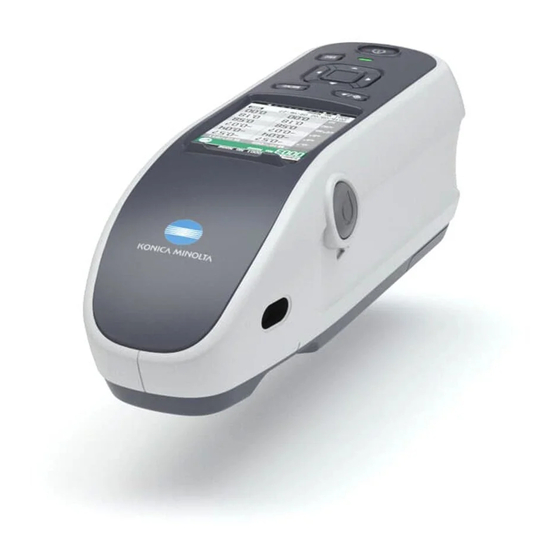
Introduction The CM-25cG is a 45-degree circumferential illumination / vertical viewing model spectrophotometer capable of measuring both color and gloss in a single measurement. Packing materials of the product Be sure to keep all packing materials used for shipping the instrument (cardboard box, cushioning material, plastic bags, etc.). -
Page 7: Backup Battery
• Do not attempt to replace the built-in backup battery. The battery should only be replaced by KONICA MINOLTA. To replace the backup battery, please contact a KONICA MINOLTA-authorized service facility. • It is recommended to manage important data using the optional SpectraMagic DX software. -
Page 8: X84; „ Notes On Storage
• If you are unable to remove dirt from the instrument through the above procedure, or if the instrument becomes scratched, contact a KONICA MINOLTA-authorized service facility. • If you are unable to remove dirt from the instrument or if the instrument becomes scratched, contact a KONICA MINOLTA-authorized service facility. -
Page 9: X84; „ Disposal Method
Disposal Method „ „ • Make sure that the instrument, all accessories (including any used batteries), and the packing materials are either disposed of or recycled correctly in accordance with local laws and regulations. • In the United States and Canada, you can recycle your lithium-ion battery through the Call2Recycle program. For more information, in the United States visit www.call2recycle.org and in Canada visit www.call2recycle.ca. -
Page 10: Table Of Contents
Table of Contents Notification for California Customers....i Calibration .............32 „ „ Safety Symbols ..........ii „ „ Zero Calibration ..........32 „ „ Notes on this Manual ........ii „ „ White Calibration and Gloss Calibration ..34 „ „ Introduction .............3 User Calibration .......... - Page 11 Chapter 5 Troubleshooting ..116 Measurement Option Settings ....... 75 „ „ Auto Average (1 to 10) ....... 76 … „ Message List ..........117 Manual Average (1 to 30)......77 … „ Display Condition Settings ......78 „ „ Troubleshooting ...........119 Observer/Illuminant 1 ......
-
Page 12: X84; „ Conventions
Conventions „ „ This manual describes how to safely operate the CM-25cG using a specific procedure to perform measurement. · Viewing Pages Symbols used in this manual are explained below. * Explanatory pages are constructed as follows. (The content of the explanatory illustration will differ from the actual page.) -
Page 13: Chapter 1 Before Using The Instrument
Chapter Before Using the Instrument Accessories ............11 Standard Accessories ..........11 Optional Accessories ..........12 System Diagram ...........14 Names and Functions of Parts .......15 Cleaning Parts ............18 Points to Remember ..........19 Initial Settings ............19 Control Panel ............19 Menus ..............23 Data Saving .............25... -
Page 14: Accessories
Accessories Standard and optional accessories are available with the instrument. The shape of some products may be different from those shown. Memo *Not available in all areas. Standard Accessories „ „ AC Adapter AC-A305J/L/M (UBX305)* Used to supply power from an AC outlet to the instrument. Input: 100 to 240 V 50/60 Hz 0.15 A Output: 5 V... -
Page 15: X84; „ Optional Accessories
Flat Type Battery Cover CM-A218 Used when the measurement surface of a target specimen is lower than the bottom surface of the instrument. Cleaning Cloth Used to clean the calibration plate. Optional Accessories „ „ Hard Case CM-A236 Used for carrying the instrument and accessories by hand. Replacement Lithium-ion Battery CM-A235 (RRC1120)* This battery is a replacement for the standard lithium-ion battery. - Page 16 Color Data Software SpectraMagic DX Used to control the instrument and manage data from a PC. Color Data Software SpectraMagic NX (*Ver. 2.8 or later) Used to control the instrument and manage data from a PC. Battery Charger CM-A237 (RRC-SCC1120)* Used as the dedicated charger to charge the lithium-ion battery.
-
Page 17: System Diagram
IF-A26 Wrist Strap CR-A73 Optional Accessories Color Data Software SpectraMagic DX Color Data Software SpectraMagic NX Spectrophotometer (Version 2.8 or later) CM-25cG Optional Accessories Color Plates (14 colors) Battery Charger CM-A237* Flat Type Battery Cover Lithium-ion Battery CM-A218 Bluetooth Module... -
Page 18: Names And Functions Of Parts
Names and Functions of Parts 1 LCD screen Displays settings, measurement results, messages, etc. 2 Control panel The keys are used to switch screens and to select, set, or save settings. For details, refer to page 21 “Control Keys”. 3 Charging lamp Lights up orange when charging via USB power. - Page 19 10 Specimen measuring port This is the aperture for measuring samples. 11 Measurement area switch Switches the measurement area. 12 Screw holes for securing Used for mounting the instrument to jigs or other components. 13 Battery compartment cover Slide this cover to replace the battery or attach the Bluetooth module. When the measurement surface and the bottom of the instrument are the Memo same height, the standard battery compartment cover should be used.
-
Page 20: X85; „ Calibration Stage Cm-A217
Calibration Stage CM-A217 … „ 1 Cap This black cap is used to protect the white calibration plate and gloss calibration plate. Attach the cap to the white calibration plate and the gloss calibration Notes plate when they are not being used. 2 Zero calibration hole Used to perform zero calibration. -
Page 21: X84; „ Cleaning Parts
Cleaning Parts „ „ Zero Calibration Hole (Calibration Stage) … „ Use a blower to blow off any dust in the zero calibration hole. In addition, cleaning directly with the blower can be performed by removing the cover. In such cases, be careful not to leave behind fingerprints or the like. White Calibration / Gloss Calibration Plate …... -
Page 22: Points To Remember
Points to Remember Initial Settings „ „ When first turning the instrument ON after purchasing, the language setting screen will be displayed. Please select the language. The language selection menu can be displayed by turning ON the instrument while holding down [MENU]. -
Page 23: X85; „ Status Bar
Status Bar … „ This section describes the icons displayed at the top of the screen. Display Description (Status) Meaning Equipment diagnosis result Pass / Warning / No diagnosis /None Protect data No overwriting, editing, or deletion of target /None data / No data protection Flash status Flash ready / Insufficient light... -
Page 24: X85; „ Control Keys
Control Keys … „ Use these keys to set items or change screens according to the guide on the LCD screen. Switches between the <Target> screen and <Sample> screen. (Target/Sample) key 2 [MENU] key Displays the <Settings> screen. 3 [ESC] key Returns to the previous screen without configuring the settings when pressed on the <Settings>... -
Page 25: X85; „ Changing Screens
Changing Screens … „... -
Page 26: X84; „ Menus
Menus „ „ Target menu Measurement cond. Print data P.53 Measurement mode P.74 Color & Gloss / Color only / Gloss only Edit name P.54 Measurement setup Data management Auto average P.76 Delete data P.55 1 to 10 Times OK/Cancel Manual average P.77 Set group... - Page 27 Setting Instrument setup Default data setup P.65 User type P.88 Default tolerance P.66 Administrator / Worker OK/Cancel Language P.89 Warning level P.67 English/Japanese/German/ 0 to 100% French/Spanish/Italian/ Chinese/Portuguese/ Polish/Russian/Turkish Parametric coef. P.68 l (CMC), c (CMC), l (ΔE*94), Date format P.90 c (ΔE*94), h (ΔE*94), [yyyy/mm/dd] / [mm/dd/...
-
Page 28: X84; „ Data Saving
Data Saving „ „ Data used with this instrument are saved automatically within the instrument. Data on the instrument can also be imported to a PC using the optional Color Data Software “SpectraMagic DX”. -
Page 29: Chapter 2 Measurement
Chapter Measurement Flow of Measurement ...........27 Preparation ............28 Calibration ............32 Zero Calibration ............32 White Calibration and Gloss Calibration ....34 User Calibration ............36 Setting a Specimen ..........37 Viewfinder ...............37 Measurement ............38 Measurement/Data Display Screen ......39 Handling the Sample ..........42 Print ................43 Edit Name ...............44 Sample Data Management........45 Pass/Fail Judgment for Color Difference ....50... -
Page 30: Flow Of Measurement
Flow of Measurement Optional Settings Basic Procedure „ „ Turning the Power ON (Page 30) Language selection (Page 89) *As necessary (after initialization, etc.) Measurement condition settings (Page 73) *When required depending on the Measurement area selection (Page 31) measurement conditions ... -
Page 31: Preparation
Preparation Attaching the Wrist Strap … „ Attaching the wrist strap Wrist strap attaching position... -
Page 32: X85; „ Inserting The Battery
Inserting the Battery … „ This instrument can be powered from a lithium-ion battery, but use of the AC adapter or USB bus power is recommended for extended periods of use. A lithium-ion battery installed in the instrument will be charged whenever the AC adapter or USB bus power is used, regardless of whether the instrument is turned ON or OFF. -
Page 33: X85; „ Connecting The Ac Adapter
Connecting the AC Adapter … „ • The lithium-ion battery must always be installed, even when using external power. Notes • To supply AC power to the instrument, always use the AC adapter (AC-A305J/L/M) supplied with the instrument. • Firmly push the AC adapter power plug or USB cable completely into the outlet. Powering the instrument from the USB cable will charge the lithium-ion battery. -
Page 34: X85; „ Measurement Area Selection
Measurement Area Selection … „ Select the measurement area. The selected measurement area can be checked on the status bar displayed on the screen. (Refer to page 20.) Operating Procedure Operate the measurement area switch on the instrument. Use the measurement area switch on the bottom of the instrument to set the measurement area to MAV or SAV. -
Page 35: Calibration
Calibration Select the measurement area using the switch beforehand. The following three types of calibration can be performed with this instrument. • Zero calibration: Only the amount of stray light is measured in advance in order to eliminate the effects of the stray light. - Page 36 Use [] or [] to move the cursor to “Calibration (Including Zero Cal.)”, and then press the [Confirmation] key. Set the instrument in the calibration stage to measure the calibration stage’s zero calibration hole. Please set the instrument on the zero calibration box and press the measurement Place the...
-
Page 37: X84; „ White Calibration And Gloss Calibration
White Calibration and Gloss Calibration „ „ A message prompting white calibration is displayed on the instrument after the power is turned ON. • If the calibration interval is turned ON and a time is configured, a message prompting white calibration will be Memo displayed the next time the power is turned ON or when measurement is performed after the set time has passed since the previous white calibration. - Page 38 Set the instrument in the calibration stage in order to measure the calibration stage’s white calibration plate. • Verify that the White ID shown on the screen and the Notes calibration stage number match. Please set the instrument on the white calibration plate and press the measurement button.
-
Page 39: X84; „ User Calibration
User Calibration „ „ You can perform calibration by using your own reference plate and calibration data instead of white calibration. The calibration data for user calibration can be specified by connecting the instrument to a PC and using the optional Color Data Software “SpectraMagic DX”. -
Page 40: Setting A Specimen
Setting a Specimen To measure with this instrument, select the measurement area and set the instrument on the specimen. Either MAV or SAV can be selected as the measurement area depending on the specimen being measured and the application. Switch the measurement area to be measured using the measurement area switch. Notes Viewfinder „... -
Page 41: Measurement
Measurement • Prior to the start of measurement, be sure to perform white calibration. For details, refer to “White Notes Calibration and Gloss Calibration” on page 34. • To display the color difference, target colors must be set before measurement. • To measure a target, select the target number before measurement. -
Page 42: X84; „ Measurement/Data Display Screen
Measurement/Data Display Screen „ „ Target List Screen • For every data entry, the target No. and name is displayed in the column above, and the measurement date and time are displayed in the column below. A pseudocolor is displayed at the right end only if data exists. However, no pseudocolor is displayed when measuring only gloss. - Page 43 Sample List Screen • If the data does not exist, the measurement list screen will not be displayed. • For every data entry, the sample No. and name is displayed in the column above, and the measurement date and time are displayed in the column below. A pseudocolor is displayed at the right end only if data exists. However, no pseudocolor is displayed when measuring only gloss.
- Page 44 Changing Screens The detail screen is displayed only for screens with the appropriate format selected under <Display type>. [Target] List [Target] Details Use [] or [] to go to the next display type. Use [] or [] to move Absolute value Custom Abs.
-
Page 45: Handling The Sample
Handling the Sample <Screen transition> The keys can be used to switch between screens displaying the data. On the <Sample menu> screen, the following operations are available for the sample data. <Print data> Print the current sample data with the printer. <Edit name>... -
Page 46: X84; „ Print
Print „ „ Print the sample data. The instrument must be connected to the serial printer in advance. For instructions on how to connect the instrument to a serial printer, refer to page 103 “Connecting to a Printer/Barcode Reader”. • Display the sample to be printed on the <Sample> screen in advance. Notes • If a proper connection is not established, printing will not be possible. -
Page 47: X84; „ Edit Name
Edit Name „ „ Name the sample data. Display the name of the sample to be edited on the <Sample> screen in advance. Setting Procedure Start the procedure from the <Sample menu> screen. Use [] or [] to move the cursor to “Edit name”, Sample 0003 Bumper and then press the [Confirmation] key. -
Page 48: X84; „ Sample Data Management
Sample Data Management „ „ Sample data management allows users to delete sample data, copy the sample to the target, change the link to the target, change the list position, and delete all data. Setting Procedure Start the procedure from the <Sample menu> screen. Use [] or [] to move the cursor to “Data management”, and then press the [Confirmation] key to display the <Data management>... -
Page 49: X85; „ Set Sample As Target
Set Sample as Target … „ Sample data can be copied to target data and registered. Display the sample to be set as the target on the <Sample> screen in advance. Setting Procedure Start the procedure from the <Sample menu> - <Data management> screen. • Target colors are stored with setting numbers from 0001 to 2500 being assigned. -
Page 50: X85; „ Change Target Reference
Change Target Reference … „ The target data acting as a reference for the sample data can be changed. Display the sample for which the target reference is to be changed on the <Sample> screen in advance. Setting Procedure Start the procedure from the <Sample menu> - <Data management> screen. Use [] or [] to move the cursor to “Change Sample 0003 Bumper... -
Page 51: X85; „ Change List Position
Change List Position … „ Specifying sample numbers allows for specified sample to be selected without the need to scroll the screen. Setting Procedure Start the procedure from the <Sample menu> - <Data management> screen. Use [] or [] to move the cursor to “Change list Sample 0003 Bumper position”, and then press the [Confirmation] key. -
Page 52: X85; „ Delete All Data
Delete All Data … „ Delete all sample data. Setting Procedure Start the procedure from the <Sample menu> - <Data management> screen. Use [] or [] to move the cursor to “Delete all Sample 0003 Bumper data”, and then press the [Confirmation] key. The <Delete all data>... -
Page 53: Pass/Fail Judgment For Color Difference
Pass/Fail Judgment for Color Difference With this instrument, tolerances can be set for the color difference of the sample data from the target color data to perform judgment. For the procedure on setting tolerances, refer to page 62 “Tolerance Settings” and page 66 “Default Tolerance Setting”. - Page 54 <Sample> Display Screen If no relevant target data has been set, no color difference value or pass/fail mark will be displayed. Notes Display when all of color differences and gloss value differences do not exceed or near the tolerance Absolute value, Difference, Abs. & Diff., and Custom screens Ex.: Abs.
-
Page 55: Color Difference Target Color Operation
Color Difference Target Color Operation To measure the color difference between two specimens, the color of one of the specimens must be set as the target color. This instrument can store up to 2,500 target colors and 7,500 sample colors. • Target colors are stored with setting numbers from 0001 to 2500 being assigned. -
Page 56: X84; „ Print
Print „ „ Print the target color data. The instrument must be connected to the serial printer in advance. For instructions on how to connect the instrument to a serial printer, refer to page 103 “Connecting to a Printer/Barcode Reader”. • Display the target color to be printed on the <Target>... -
Page 57: X84; „ Edit Name
Edit Name „ „ Name the target color data. Operating Procedure Start the procedure from the <Target menu> screen. Use [] or [] to move the cursor to “Edit name”, Target and then press the [Confirmation] key. The <Edit name> screen is displayed. Target menu [0003] Print data Edit name... -
Page 58: X84; „ Target Data Management
Target Data Management „ „ Target data management allows users to enforce target data restrictions, perform grouping, change list positions, edit target filters, protect data, and delete all data. Operating Procedure Start the procedure from the <Target menu> screen. Use [] or [] to move the cursor to “Data management”, and then press the [Confirmation] key to display the <Data management>... -
Page 59: X85; „ Set Group
Set Group … „ In order to facilitate classification of targets into groups, up to five groups to which data should be categorized can be configured. After the targets have been registered to a group, the filtering function can be used to display only the selected target data. -
Page 60: X85; „ Change List Position
Change List Position … „ Specifying target numbers allows for specified targets to be displayed without the need to scroll the screen. Operating Procedure Start the procedure from the <Target menu> - <Data management> screen. Use [] or [] to move the cursor to “Change list Target position”, and then press the [Confirmation] key. -
Page 61: X85; „ Edit Target Filter
Edit Target Filter … „ The filter function makes searching for a target easier. The function allows only selected target data to be displayed by selecting only saved data or by selecting a group created in advance. The Edit Target filter is set to “OFF” when the instrument is shipped from the factory. Memo Operating Procedure Start the procedure from the <Target menu>... -
Page 62: X85; „ Data Protection
Data Protection … „ Data protection can be specified so that the saved target color settings will not be deleted or changed by accident. When the data protection is set, you cannot select “Edit name”, “Edit tolerance”, “Delete data” or “Delete all data” on the <Target menu>... -
Page 63: X85; „ Delete All Data
Delete All Data … „ Delete all the target color data that have been set. When the data is protected, “Delete all data” cannot be selected on the <Data management> screen. Notes Operating Procedure Start the procedure from the <Target menu> - <Data management> screen. Use [] or [] to move the cursor to “Delete all Sample data”, and then press the [Confirmation] key. -
Page 64: X84; „ Pass/Fail
Pass/Fail „ „ Edit the tolerance that will be used as the judgment criteria, and set the warning level and the parametric coefficient default value. If the color difference between the sample and the target exceeds the tolerance, the column of the display color value relevant to the measurement display will be displayed in red. -
Page 65: X85; „ Tolerance Settings
Tolerance Settings … „ Specify the tolerance used for pass/fail judgment of measured data for each target color. Operating Procedure Start the procedure from the <Target menu> - <Pass/Fail> screen. Use [] or [] to move the cursor to “Edit Sample tolerance”, and then press the [Confirmation] key. -
Page 66: X85; „ Warning Level Setting
Warning Level Setting … „ Warnings are displayed when the measured data nears but does not exceed the tolerance. Users can set how close the data must be to the tolerance before a warning occurs. Operating Procedure Start the procedure from the <Target menu> - <Pass/Fail> screen. Use [] or [] to move the cursor to “Warning Sample level”, and then press the [Confirmation] key. -
Page 67: X85; „ Parametric Coefficient Setting
Parametric Coefficient Setting … „ Specify the parametric coefficient used for pass/fail judgment of measured data for each target color. Operating Procedure Start the procedure from the <Target menu> - <Pass/Fail> screen. Use [] or [] to move the cursor to “Parametric Sample coef.”, and then press the [Confirmation] key. -
Page 68: X84; „ Default Data Settings
Default Data Settings „ „ This instrument allows pass/fail judgment criteria to be set for individual target color data. Until such judgment criteria are set, the instrument is set with the default tolerance. Users can edit the tolerance that will be used as the judgment criteria as well as edit the warning level and the parametric coefficient default value. -
Page 69: X85; „ Default Tolerance Setting
Default Tolerance Setting … „ • The tolerance is set to the following values when the instrument is shipped from the factory. Memo Lower limit: -1.00 Upper limit: 1.00 Δx, Δy, Δz Lower limit: -0.01 Upper limit: 0.01 Operating Procedure Start the procedure from the <Default data setup>... -
Page 70: X85; „ Warning Level Setting
Warning Level Setting … „ The warning level is set to “80%” when the instrument is shipped from the factory. Memo Operating Procedure Start the procedure from the <Setting> - <Default data setup> screen. Use [] or [] to move the cursor to “Warning Sample 0003 Bumper level”, and then press the [Confirmation] key. -
Page 71: X85; „ Parametric Coefficient Setting
Parametric Coefficient Setting … „ The parametric coef. is set to “1.00” when the instrument is shipped from the factory. Memo Operating Procedure Start the procedure from the <Setting> - <Default data setup> screen. Use [] or [] to move the cursor to “Parametric Sample 0003 Bumper coef.”, and then press the [Confirmation] key. -
Page 72: X85; „ Set Group
Set Group … „ Create groups for registering targets in advance. No group name is set when the instrument is shipped from the factory. Memo Operating Procedure Start the procedure from the <Setting> - <Default data setup> screen. Use [] or [] to move the cursor to “Set group”, Sample 0003 Bumper and then press the [Confirmation] key. - Page 73 Repeat step 2 until the necessary characters have been entered. • To delete the character to the left of the cursor in the text box, move the cursor to [×] and press the [Confirmation] key. After inputting the characters, move the cursor to [Save] and press the [Confirmation] key.
-
Page 75: Chapter 3 Setup
Chapter Setup Measurement Condition Settings......73 Measurement Condition Settings......73 Measurement Option Settings .........75 Display Condition Settings ........78 Display Settings ............82 Instrument Settings ..........87 Measurement Instrument Option Settings ....87... -
Page 76: Measurement Condition Settings
Measurement Condition Settings This instrument requires measurement condition settings (measurement mode, average count, observer/ illuminant, and display) to be configured before measurement can be started. Measurement Condition Settings „ „ To set measurement conditions, select the setting from the <Measurement cond.> menu. The following four items can be specified as the measurement conditions: • Measurement mode : S elect the combination of colorimetry and gloss measurement. -
Page 77: X85; „ Measurement Mode
Measurement Mode … „ Select the combination of colorimetry and gloss measurement. The measurement mode is set to “Color & Gloss” when shipped from the factory. Memo Operating Procedure Start the procedure from the <Measurement cond.> screen. Use [] or [] to move the cursor to “Measurement Sample 0003 Bumper mode”, and then press the [Confirmation] key. -
Page 78: X84; „ Measurement Option Settings
Measurement Option Settings „ „ To set measurement options, select “Measurement setup” from the <Measurement cond.> menu screen. Select or specify the following items as the measurement options: • Auto average (1 to 10) : Specify the number of measurements for auto averaging. • Manual average (1 to 30) : Specify the number of measurements for manual averaging. -
Page 79: X85; „ Auto Average (1 To 10)
Auto Average (1 to 10) … „ Specify the number of measurements for auto averaging. Every time the measurement button is pressed, the average of the data obtained from the specified number of continuous measurements is determined as sample data. “1 Times”... -
Page 80: X85; „ Manual Average (1 To 30)
Manual Average (1 to 30) … „ Specify the number of measurements for manual averaging. The average of the data obtained from the measurements conducted by pressing the measurement button the specified number of times is determined as sample data. “1 Times”... -
Page 81: X84; „ Display Condition Settings
Display Condition Settings „ „ To set display conditions, select “Observer/Illuminant” from the <Measurement cond.> menu screen. The following two observer/illuminant settings can be configured for the display conditions. • Observer/Illuminant 1: Select the observer/illuminant used to measure the colorimetric data. • Observer/Illuminant 2: Select the secondary illuminant used for MI (metamerism index) calculation, etc. -
Page 82: X85; „ Observer/Illuminant 1
Observer/Illuminant 1 … „ Select an observer angle of either 2° or 10° and the illuminant used to measure colorimetric data. Observer/Illuminant 1 is set to “10°/D65” when the instrument is shipped from the factory. Memo Operating Procedure Start the procedure from the <Measurement cond.> - <Observer/Illuminant> screen. Use [] or [] to move the cursor to “Observer/ Sample 0003 Bumper... - Page 83 Press the [Confirmation] key. The selection is confirmed and the screen returns to the <Observer/Illuminant> screen. If [ESC] is pressed without pressing the [Confirmation] Notes key, the settings will not be changed and the screen will return to the <Observer/Illuminant> screen.
-
Page 84: X85; „ Observer/Illuminant 2
Observer/Illuminant 2 … „ Select the secondary illuminant used for MI (metamerism index) calculation, etc. Observer/Illuminant 2 is set to “10°/F11” when the instrument is shipped from the factory. Memo Operating Procedure Start the procedure from the <Measurement cond.> - <Observer/Illuminant> screen. Use [] or [] to move the cursor to “Observer/ Sample 0003 Bumper... -
Page 85: X84; „ Display Settings
Display Settings „ „ To set display settings, select “Display cond.” from the <Measurement cond.> menu screen. The following four items (three items and 14 custom display items) can be specified as the display conditions. • Display type : Select the screen to be displayed. • Color space : Select the color space to be displayed. -
Page 86: X85; „ Display Type
Display Type … „ Configure the display type for the measurement results. All display types are selected when the instrument is shipped from the factory. Memo Operating Procedure Start the procedure from the <Measurement cond.> - <Display cond.> screen. Use [] or [] to move the cursor to “Display type”, Sample 0003 Bumper and then press the [Confirmation] key. -
Page 87: X85; „ Color Space
Color Space … „ Select the color space to be used. The color space is set to “L*a*b*” when the instrument is shipped from the factory. Memo Operating Procedure Start the procedure from the <Measurement cond.> - <Display cond.> screen. Use [] or [] to move the cursor to “Color space”, Sample 0003 Bumper... -
Page 88: X85; „ Equation
Equation … „ Select the color difference equation to be used. The color difference equation is set to “ΔE*ab” when the instrument is shipped from the factory. Memo Operating Procedure Start the procedure from the <Measurement cond.> - <Display cond.> screen. Use [] or [] to move the cursor to “Equation”, Sample 0003 Bumper... -
Page 89: X85; „ Custom
Custom … „ Select the items, including the color space, color difference equation, or index, to be used. Up to 14 items (Custom 01 to Custom 14) to be displayed can be set. The custom display items are set to “None” when the instrument is shipped from the factory. Memo Operating Procedure Start the procedure from the <Measurement cond.>... -
Page 90: Instrument Settings
Instrument Settings Measurement Instrument Option Settings „ „ To set measurement instrument options, select “Instrument setup” from the <Setting> screen. Operating Procedure Start the procedure from the measurement screen. Press [MENU], and then use [] or [] to display the Sample 0003 Bumper <Setting>... -
Page 91: X85; „ User Type
User Type … „ Settings can be protected for each user. The user type is set to “Administrator” when the instrument is shipped from the factory. Memo Operating Procedure Start the procedure from the <Setting> - <Instrument setup> screen. Use [] or [] to move the cursor to “User type”, Sample 0003 Bumper and then press the [Confirmation] key. -
Page 92: X85; „ Display Language Settings
Display Language Settings … „ This instrument allows the display language to be set. To display the language setting screen, press and hold [MENU] while starting up the instrument. The language is set to “English” when the instrument is shipped from the factory. Memo When the backup battery of the instrument has gone dead, the display language is reset to “English”. -
Page 93: X85; „ Setting The Date Format
Setting the Date Format … „ The format of the date displayed on the screen can be changed. The date format is set to “yyyy/mm/dd” when the instrument is shipped from the factory. Memo Operating Procedure Start the procedure from the <Setting> - <Instrument setup> screen. Use [] or [] to move the cursor to “Date format”, Sample 0003 Bumper... -
Page 94: X85; „ Setting The Clock
Setting the Clock … „ This instrument has a built-in clock to record the date and time of measurement. Because the date and time have been set at the factory, there is no need to change these settings under normal conditions. If necessary, however, the date and time settings may be configured. -
Page 95: X85; „ Screen Brightness
Screen Brightness … „ The brightness of the LCD can be set in five levels. Selecting a darker level is effective for power saving. Screen brightness is set to “3 (Standard)” when the instrument is shipped from the factory. Memo Operating Procedure Start the procedure from the <Setting>... -
Page 96: X85; „ Buzzer
Buzzer … „ Operation sounds can be set to ON or OFF. The buzzer is set to “ON” when the instrument is shipped from the factory. Memo Operating Procedure Start the procedure from the <Setting> - <Instrument setup> screen. Use [] or [] to move the cursor to “Beep”, and Sample 0003 Bumper then press the [Confirmation] key. -
Page 97: X85; „ Auto Power Off
Auto Power Off … „ The amount of time before switching the power off can be set. Auto power off is set to “0 (minute)” (no auto power off) when the instrument is shipped from the factory. Memo Operating Procedure Start the procedure from the <Setting>... -
Page 99: Chapter 4 Other Functions
Chapter Other Functions Connecting to an External Device ......97 Connecting to a Personal Computer ....97 ‹ „ Connecting via USB Cable ........98 Connecting via Bluetooth ........99 Communication Setup ...........100 ‹ Connecting to a Printer/Barcode Reader ..103 „ Instrument Preparation .........104 System Settings ..........109 Calibration Setup ...........109 Displaying Diagnosis Information ......113... -
Page 100: Connecting To An External Device
Connecting to an External Device This instrument includes a USB connection terminal and a Bluetooth function (when the optional Bluetooth module is attached). The supplied USB cable (IF-A26) can be used to connect the instrument to a PC, or the Bluetooth communication function can be used to connect the instrument to a PC or a printer, allowing for data communication and printing. -
Page 101: Z „ Connecting Via Usb Cable
Connecting via USB Cable „ Connect the instrument to a PC with the supplied USB cable IF-A26 (2 m). • To connect the instrument to a PC, the dedicated USB driver must be installed. The necessary drivers will be Notes installed automatically. -
Page 102: Z „ Connecting Via Bluetooth
Connecting via Bluetooth „ Connect the instrument to a PC with Bluetooth communication functionality using the optional Bluetooth module. • The instrument’s Bluetooth function enables data communication with a connected PC and printing from a Notes Bluetooth computer. Connecting to both a PC and a printer/scanner at the same time, however, is not possible. -
Page 103: X84; „ Communication Setup
Communication Setup „ „ Turn ON the Bluetooth function and configure the meter PIN code. Operating Procedure Start the procedure from the measurement screen. Press [MENU], and then use [] or [] to display the Sample 0003 Bumper <Setting> screen. To return to the previous screen, press [MENU] or [ESC]. - Page 104 Use [] or [] to move the cursor to “ON”, and then press the [Confirmation] key. The instrument’s Bluetooth function is turned ON and the display will return to the <Communication setup> screen. The Bluetooth icon will be displayed in the status bar. Bluetooth To configure the Bluetooth PIN code, go to step 3 to continue.
-
Page 105: X84; Pc Connection
PC Connection „ With the PC as a host, a connection to the instrument can be established using Bluetooth communication. Operating Procedure Verify that the instrument power has been turned Verify that the Bluetooth function on the instrument Sample 0003 Bumper has been turned ON. -
Page 106: X8B; „ Connecting To A Printer/Barcode Reader
Connecting to a Printer/Barcode ‹ „ Reader Connecting the instrument to a printer or barcode scanner via the Bluetooth function enables printing of various data such as measurement results or scanning of names for data to save to the instrument. • With the CM-A219 Bluetooth module installed, the Bluetooth function of this instrument enables data Notes communication to a PC, data printing to the CM-A234 Bluetooth printer, and reading of data names from a... -
Page 107: Instrument Preparation
Instrument Preparation „ Connecting the Bluetooth module to the instrument, and turn ON the instrument’s Bluetooth function. (Refer to page 99.) Until the instrument’s Bluetooth function is turned ON, registration and automatic printing configuration of Notes the Bluetooth printer/reader is not possible. Registering a Bluetooth Address …... -
Page 108: X85; „ Pin Code Configuration
PIN Code Configuration … „ Enter the PIN set for the printer/scanner (already confirmed). Operating Procedure Start the procedure from the <Setting> - <Communication setup> screen. Use [] or [] to move the cursor to “Printer PIN code” or “Scanner PIN code”, and then press the [Confirmation] key. -
Page 109: X85; „ Printing Data
Printing Data … „ Print the sample data or target data with the printer. • The instrument must be connected to the printer in advance. Notes • The optional accessory Bluetooth printer CM-A234 can only print text. Spectral graphs, color difference graphs, and other graphics displayed on the instrument cannot be printed. -
Page 110: X85; „ Auto Print
Auto Print … „ Measurement results can be automatically printed for every measurement. • The instrument must be connected to the printer in advance. Notes • The optional accessory Bluetooth printer CM-A234 can only print text. Spectral graphs, color difference graphs, and other graphics displayed on the instrument cannot be printed. - Page 111 Print Example 3 Display type set to “Abs. & Diff.” Sample 0003 Bumper No Name 0004 10°/D65 2°/C 99.07 99.03 -0.09 -0.05 0.03 0.01 0.08 0.07 ∆ L * -0.05 0.05 ∆ a * 0.01 -0.08 ∆ b * 0.09 0.12 ∆...
-
Page 112: System Settings
System Settings This section explains how to configure calibration, how to display the instrument diagnosis info., and how to display the instrument info. Operating Procedure Start the procedure from the measurement screen. Press [MENU], and then use [] or [] to display the Sample 0003 Bumper <Setting>... -
Page 113: X85; „ Calibration Interval Messages
Calibration Interval Messages … „ If the instrument has not been used for an extended period of time since the previous measurement, a message prompting white calibration will appear after start-up and before measurement. The time interval between the previous calibration and when the message is displayed can be configured. The interval until the calibration is displayed is set to “8 (hour)”... -
Page 114: X85; „ Annual Calibration Messages
The date of the next calibration is Annual calibration specified before the instrument is shipped from the factory or during KONICA MINOLTA calibration service (or maintenance) and cannot be changed. Next date: 2017/10/10 Press the [Confirmation] key. -
Page 115: X85; „ User Calibration
User Calibration … „ You can perform calibration by using your own reference plate and calibration data instead of white calibration. The calibration data for user calibration can be specified by connecting the instrument to a PC and using the optional Color Data Software “SpectraMagic DX”. -
Page 116: X84; „ Displaying Diagnosis Information
Displaying Diagnosis Information „ „ The results of the instrument status diagnosis using the optional “SpectraMagic DX” are displayed. For details, refer to the instruction manual of SpectraMagic DX. Operating Procedure Start the procedure from the <Setting> screen. Use [] or [] to move the cursor to “Diagnosis Sample 0003 Bumper info.”, and then press the [Confirmation] key. -
Page 117: X84; „ Displaying The Instrument Information
The instrument information is displayed. Display Items Instrument info. Product name: Instrument product name „ Product name Version: Instrument firmware version „ CM-25cG Serial No.: Instrument serial No. „ Version 1.00.0000 Serial No. 1234567 Press [ESC]. The display will return to the <Setting> screen. -
Page 119: Chapter 5 Troubleshooting
Chapter Troubleshooting Message List ............117 Troubleshooting ..........119... -
Page 120: Message List
Message List Error message: The operation is not correct. Follow the instructions displayed immediately. There is no xenon output. Restart and try measuring again. If the error occurs again, please contact the nearest service center. There was an error with color measurement device. Restart and try measuring again. If the error occurs again, please contact the nearest service center. - Page 121 Caution: The setting or operation is not correct. The reflectance is outside the range of guaranteed performance. The gloss value is outside the range of guaranteed performance. Check the USB connection. P.97 The target is protected. P.59 The date is incorrect. P.91 The set tolerance range is incorrect.
-
Page 122: Troubleshooting
If an abnormality has occurred with the instrument, take the necessary actions as given in the table below. If the instrument still does not work properly, turn the power OFF and temporarily disconnect the battery. Reinsert the battery and turn the power back ON. If the symptom remains, contact a KONICA MINOLTA-authorized service facility. -
Page 123: Chapter 6 Appendix
Chapter Appendix Specifications .............121 Dimensions ............123... -
Page 124: Specifications
Inter-instrument Within ΔE*ab 0.15 (MAV) agreement (Average for 12 BCRA Series II color tiles compared to values measured with a master body under Konica Minolta standard measurement conditions) Observer 2° or 10° Standard Observer Illuminant A, C, D50, D65, F2, F6, F7, F8, F10, F11, F12, ID50, ID65, User illuminant... - Page 125 Displayed languages Japanese, English, German, French, Italian, Spanish, Chinese (Simplified), Portuguese, Russian, Turkish, Polish Display 2.7-inch TFT color LCD Interfaces USB 2.0; Bluetooth (SPP compatible. Using optional Bluetooth Module) Data memory Target data: 2,500 measurements; Sample data: 7,500 measurements Power Rechargeable Lithium-ion battery, USB bus power Charging time Approx.
-
Page 126: Dimensions
Dimensions (Unit: mm) 80.5 81.3 (Mounting screw height) ø35 58.5 2-M3 mounting screw, depth 3.5 (Height from measuring port to screw: 4 mm) - Page 129 < CAUTION > KONICA MINOLTA WILL NOT BE LIABLE FOR ANY DAMAGES RESULTING FROM THE MISUSE, MISHANDLING, UNAUTHORIZED MODIFICATION, ETC. OF THIS PRODUCT, OR FOR ANY INDIRECT OR INCIDENTAL DAMAGES (INCLUDING BUT NOT LIMITED TO LOSS OF BUSINESS PROFITS, INTERRUPTION OF BUSINESS, ETC.) DUE TO...
- Page 130 En 9222-A9AG-13 ©2016 KONICA MINOLTA, INC. BHMBGA...