Table of Contents
Troubleshooting

Related Manuals for Powermatic 2013


Summary of Contents for Powermatic 2013
- Page 1 Operating Instructions and Parts Manual 20”and 24” Band Saws Models 2013 and 2415 WMH TOOL GROUP 2420 Vantage Drive Elgin, Illinois 60124 Part No. M-1791257 Ph.: 800-274-6848 Revision C 8/06 www.wmhtoolgroup.com Copyright © WMH Tool Group...
-
Page 2: Warranty And Service
This warranty covers only the initial purchaser of the product. WHAT IS THE PERIOD OF COVERAGE? The general POWERMATIC warranty lasts for the time period specified in the product literature of each product. WHAT IS NOT COVERED? The Five Year Warranty does not cover products used for commercial, industrial or educational purposes. Products with a Five Year Warranty that are used for commercial, industrial or education purposes revert to a One Year Warranty. -
Page 3: Table Of Contents
Troubleshooting – Operational Problems ... 29 Troubleshooting – Mechanical and Electrical Problems ... 31 Replacement Parts... 32 Parts List: Saw Body Assembly (2013 Band Saw)... 33 Parts List: Saw Body Assembly (2415 Band Saw)... 34 Saw Body Assembly (2013 and 2415) ... 35... - Page 4 Parts List: Guide Bracket Assembly (2415 Band Saw) ... 51 Guide Bracket Assembly (2013 and 2415)... 53 Electrical Connections: 230 Volt, Single Phase – Model 2013 Band Saw ONLY ... 54 Electrical Connections: 230 Volt, Single Phase – Model 2415 Band Saw ONLY ... 55 Electrical Connections: 230 Volt, 3 Phase –...
-
Page 5: Warning
4. This band saw is designed and intended for use by properly trained and experienced personnel only. If you are not familiar with the proper and safe operation of a band saw, do not use until proper training and knowledge have been obtained. -
Page 6: Save These Instructions
blahblahblah 21. Give your work undivided attention. Looking around, carrying on a conversation and “horse-play” are careless acts that can result in serious injury. 22. Maintain a balanced stance at all times so that you do not fall or lean against the blade or other moving parts. -
Page 7: Introduction
This manual is provided by WMH Tool Group covering the safe operation and maintenance procedures for a Powermatic Model 2013 or 2415 Band Saw. This manual contains instructions on installation, safety precautions, general operating procedures, maintenance instructions and parts breakdown. This machine has been designed and constructed to provide years of trouble free operation if used in accordance with instructions set forth in this manual. -
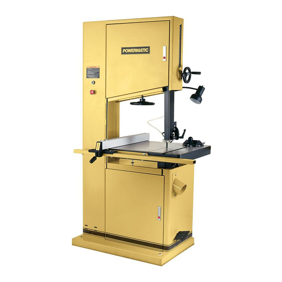
Page 8: Features And Terminology
Features and Terminology (Model 2415 shown) -
Page 9: Unpacking
Open shipping container and check for shipping damage. Report any damage immediately to your distributor and shipping agent. Do not discard any shipping material until the Band Saw is set up and running properly. Compare the contents of your container with the following parts list to make sure all parts are intact. -
Page 10: Assembly
Installing Fence and Rails 1. Mount the front rail (A, Figure 1) to the saw table with two 5/16 x 1-1/4 hex cap screws, two 5/16 lock washers, and two 5/16 flat washers. - Page 11 6. Attach the fence (D, Figure 2) to the fence body (E, Figure 2) with four 5/16 x 3/4 hex cap screws, four 5/16 lock washers, and four 5/16 flat washers. Hand tighten the screws only. 7. Place the fence assembly onto the guide rail and against the edge of the miter slot, as shown in Figure 2.
-
Page 12: Dust Collection
(minimum of 600 CFM). Attach the hose of the dust collector to the 4” dust port below the band saw table (Figure 6). Secure with a hose clamp or duct tape. NOTE: Dryer vent hose is not acceptable for wood dust collection. -
Page 13: Extension Cords
Extension cords extension recommended for the 2013 or 2415 Band Saw. But if one is necessary, make sure the cord rating is suitable for the amperage listed on the machine’s motor plate. An undersize cord will cause a drop in line voltage resulting in loss of power and overheating. -
Page 14: Converting From 230 Volt To 460 Volt (Three Phase Only)
On the three-phase unit, after wiring has been completed, you should check that the wires have been connected properly: 1. Open lower front door of the Band Saw. 2. Connect machine to power source and press the start button, shown in Figure 28, for just an instant, then press the stop button. -
Page 15: Adjustments
3. Tighten the lever (Figure 10). NOTE: The lever, shown in Figure 10, can be pivoted so that it doesn’t contact the band saw surface. Simply lift straight out on the lever and rotate it on the pin, then release it making sure it seats itself on the pin. -
Page 16: Installing/Changing Blades
9. Position blade on the middle of the upper and lower wheels. 10. Replace table insert and set screw. 11. Before operating the band saw, the new blade must be tensioned and tracked properly. Find instructions for tensioning and tracking the blade under “Blade Tension”... -
Page 17: Blade Tracking
Keep in mind that too little or too much blade tension can cause blade breakage and/or poor cutting performance. TIP: When the band saw is not being used, slightly release the tension on the blade – this will prolong the blade’s life. Make a note of the specific tension setting for that particular blade, as shown on the gauge (D, Figure 14). -
Page 18: Upper Blade Guide Assembly
Upper Blade Guide Assembly 1. Disconnect machine from power source. 2. Loosen lock knob (see B, Figure 14) and raise or lower upper blade guide assembly by turning the handwheel (C, Figure 14). 3. Position the blade guide assembly about 3/16”... -
Page 19: Lower Blade Guides And Lower Support Bearing
12. Adjust the support bearing until it lightly contacts the dollar bill. 13. When support bearing complete, remove dollar bill and tighten nut (E, Figure 19). Lower Blade Guides and Lower Support Bearing 1. Disconnect machine from power source. 2. Blade must already be tensioned and tracking properly. -
Page 20: Miter Gauge
Miter Gauge A miter gauge is provided for crosscutting operations. Install the miter gauge by sliding the end of the miter gauge bar into the T-slot in the table, as shown in Figure 22. To adjust the angle of the miter gauge: 1. -
Page 21: Belt Alignment
(Figure 28). After the STOP button has been pushed, it remains engaged. Rotate the STOP button clockwise to release it. The Band Saw can now be restarted with the START button. After the machine is shut off,... -
Page 22: Brake Pedal
Brake Pedal An alternate method of stopping the machine is to press the brake pedal, shown in Figure 29. The band saw will shut off when the brake pedal is pressed. The brake pedal is also useful for stopping the... -
Page 23: Crosscutting
Proceed as follows: 1. Cut a scrap piece of wood about the same length as the band saw table, and joint one edge along its length, or rip it on a table saw to give it a straight edge. fence... -
Page 24: Blade Selection
3. Move the band saw fence out of the way, and carefully make a freehand cut along your drawn line on the board. Stop about midway on the board, and shut off the band saw (allow the blade to come to a complete stop) but do not allow the board to move. -
Page 25: Width
Width Band saw blades come in different standard widths, measured from the back of the blade to the tip of the tooth. Generally, wider blades are used for ripping or making straight cuts, such as resawing. Narrower blades are often used when the part being cut has curves with small radii. -
Page 26: Set
The term “set” refers to the way in which the saw teeth are bent or positioned. Bending the teeth creates a kerf that is wider than the back of the blade. Set patterns are usually selected depending upon the type of material that needs to be cut. -
Page 27: Maintenance
Unlike rubber tires for many older model band saws, the tires for the 2013 and 2415 will not require trimming, equalizing, etc., nor do they require an adhesive. Rather, they ready installation. -
Page 28: Blade Selection Guide
Follow the curve to where the approximate blade width is specified. If a radius falls between two of the curves, select the widest blade that will saw this radius. This procedure should be used for making initial blade selections. These recommendations can, of course, be adjusted to meet specific requirements of a cutting job. -
Page 29: Troubleshooting - Operational Problems
Table vibration while sawing. Incorrect blade speed. Drive belt is too slack. Incorrect choice of saw blade pitch. Saw dust or debris on band wheel. Or tire is worn/damaged. Support bearing(s) are worn. Saw blade speed is too low. Surface finish on workpiece is rough. - Page 30 Increase feed pressure. Increase feed pressure and cutting rate. Re-examine material. Select proper blade from the chart (page 28). Stop the saw and remove lodged particle. Replace blade if damaged. Correct accordingly. Select narrower blade. See chart on page 28.
-
Page 31: Troubleshooting - Mechanical And Electrical Problems
Check amp setting on motor starter. Verify that band saw is on a circuit of correct size. If circuit size is correct, there is probably a loose electrical lead. -
Page 32: Replacement Parts
Miswiring of the unit. circuit breaker or blows fuses. Switch failure. Band Saw does not Extension cord too light or too long. come up to speed. Low current. Replacement Parts Replacement parts are listed on the following pages. To order parts or reach our service department, call 1-800-274-6848 between 7:30 a.m. -
Page 33: Parts List: Saw Body Assembly (2013 Band Saw)
...2013-102F...Fuse (not shown) ... 2A... 1 ...2013-102A ...Magnetic Switch... 3Ph, 230V/460V... 1 ...2013-102ACS ...Contactor Switch for 3 Phase (not shown) ..1 ...2013-102AOR ...Overload Relay for 3 Phase (not shown)..1 ...2013-102AT ...Transformer for 3 Phase (not shown) ..1 ...2013-102AF ...Fuse (not shown) ... -
Page 34: Parts List: Saw Body Assembly (2415 Band Saw)
...2415-102ACS ...Contactor Switch for 3 Phase (not shown) ..1 ...2415-102AOR ...Overload Relay for 3 Phase (not shown)..1 ...2013-102AT ...Transformer for 3 Phase (not shown) ..1 ...2013-102AF ...Fuse (not shown) ... 1A... 1 3 ...2013-103...Switch Plate ..1 4 ...TS-069204 ...Flat Washer... -
Page 35: Saw Body Assembly (2013 And 2415)
Saw Body Assembly (2013 and 2415) -
Page 36: Parts List: Table Assembly (2013 Band Saw)
Index No. Part No. 1 ...2013-201...Carriage Bolt ... 1/2”-12x9” ... 1 2 ...6295149 ...Trunnion (Left Side) ..1 3 ...2013-203...Table Bracket ..1 4 ...TS-0680041 ...Flat Washer... 3/8”... 8 5 ...TS-0720091 ...Lock Washer ... 3/8”... 8 6 ...TS-0060061 ...Hex Cap Screw ... 3/8”-16x1-1/4” ... 8 7 ...6295154 ...Name Plate ... - Page 37 56 ...TS-0270051 ...Socket Set Screw... 5/16”-18x1/2” ... 1 57 ...TS-0270061 ...Socket Set Screw... 5/16”-18x5/8” ... 4 58 ...6294841 ...Front Rail..1 59 ...2013-259...Trunnion (Right Side)..1 60 ...2013-260...Shaft..1 61 ...2013-261...C-Ring ... S-17 ... 1 62 ...2013-262...Gear ..1 63 ...2013-263...Worm Gear...
-
Page 38: Parts List: Table Assembly (2415 Band Saw)
Index No. Part No. 1 ...2013-201...Carriage Bolt ... 1/2-12x9”... 1 2 ...6295149 ...Trunnion (Left Side) ..1 3 ...2013-203...Table Bracket ..1 4 ...TS-0680041 ...Flat Washer... 3/8”... 8 5 ...TS-0720091 ...Lock Washer ... 3/8”... 8 6 ...TS-0060061 ...Hex Cap Screw ... 3/8”-16x1-1/4” ... 8 7 ...6295154 ...Name Plate ... - Page 39 56 ...TS-0270051 ...Socket Set Screw... 5/16”-18x1/2” ... 1 57 ...TS-0270061 ...Socket Set Screw... 5/16”-18x5/8” ... 4 58 ...6294841 ...Front Rail..1 59 ...2013-259...Trunnion (Right Side)..1 60 ...2013-260...Shaft..1 61 ...2013-261...C-Ring ... S-17 ... 1 62 ...2013-262...Gear ..1 63 ...2013-263...Worm Gear...
-
Page 40: Table Assembly (2013 And 2415)
Table Assembly (2013 and 2415) -
Page 41: Parts List: Upper Wheel Base Assembly (2013 Band Saw)
Parts List: Upper Wheel Base Assembly (2013 Band Saw) Index No. Part No. Description Size 1 ...2013-301...Upper Wheel Shaft..1 2 ...TS-0680091 ...Flat Washer... 3/4”... 1 4 ...TS-0720091 ...Lock Washer ... 3/8”... 8 5 ...2013-305...Upper Wheel Shaft Bracket ..1 6 ...6295890 ...Lock Nut ... -
Page 42: Parts List: Upper Wheel Base Assembly (2415 Band Saw)
1 ...2013-301...Upper Wheel Shaft..1 2 ...TS-0680091 ...Flat Washer... 3/4”... 1 4 ...TS-0720091 ...Lock Washer ... 3/8”... 8 5 ...2013-305...Upper Wheel Shaft Bracket ..1 6 ...6295890 ...Lock Nut ... 3/4”-16 UNF ... 1 7 ...TS-0270051 ...Socket Set Screw... 5/16”-18x1/2” ... 5 8 ...6295213 ...C-Ring ... -
Page 43: Upper Wheel Base Assembly (2013 And 2415)
Upper Wheel Base Assembly (2013 and 2415) -
Page 44: Parts List: Lower Wheel Base Assembly (2013 Band Saw)
25 ...TS-0561021 ...Hex Nut ... 5/16”-18 ... 5 26 ...6295256 ...Motor ... 2HP, 1Ph ... 1 ...2013-426SC...Starting Capacitor ... 500MFD, 125VAC... 1 ...2013-426RC...Running Capacitor ... 30µF, 300VAC ... 1 ...6295331 ...Motor ... 3HP, 3Ph ... 1 27 ...TS-0051071 ...Hex Cap Screw ... 5/16”-18x1-1/2” ... 4 28 ...6295258 ...Core ... - Page 45 Index No. Part No. Description Size 53 ...TS-0720071 ...Lock Washer ... 1/4”... 4 54 ...TS-081C032...Screw ... #10-24x1/2”... 4 55 ...TS-0720051 ...Lock Washer ... #10 ... 4 56 ...TS-069204 ...Flat Washer... #10 ... 4 57 ...TS-0560071 ...Hex Nut ... #10-24... 4...
-
Page 46: Parts List: Lower Wheel Base Assembly (2415 Band Saw)
24 ...TS-0720081 ...Lock Washer ... 5/16”... 6 25 ...TS-0561021 ...Hex Nut ... 5/16”-18 ... 5 26 ...2415-426...Motor ... 3HP, 1Ph ... 1 ...2013-426SC...Starting Capacitor ... 500MFD, 125VAC... 1 ...2415-426RC...Running Capacitor ... 40µF, 250VAC ... 1 ...2415-426A ...Motor ... 5HP, 3Ph ... 1 27 ...TS-0051071 ...Hex Cap Screw ... - Page 47 Index No. Part No. Description Size 53 ...TS-0720071 ...Lock Washer ... 1/4”... 4 54 ...TS-081C032...Screw ... #10-24x1/2”... 4 55 ...TS-0720051 ...Lock Washer ... #10 ... 4 56 ...TS-069204 ...Flat Washer... #10 ... 4 57 ...TS-0560071 ...Hex Nut ... #10-24... 4...
-
Page 48: Lower Wheel Base Assembly (2013 And 2415)
Lower Wheel Base Assembly (2013 and 2415) -
Page 49: Parts List: Guide Bracket Assembly (2013 Band Saw)
Index No. Part No. 1 ...6295275 ...Guide Bar Case Bracket ..1 2 ...6295276 ...Cover..1 3 ...TS-0081031 ...Hex Cap Screw ... 5/16”-18x3/4” ... 4 4 ...TS-0050011 ...Hex Cap Screw ... 1/4”-20x1/2” ... 1 5 ...6295278 ...Pointer..1 6 ...6295279 ...Guide Bar ... - Page 50 62 ...6295327 ...Support Bearing Shaft (R)..1 63 ...TS-0270031 ...Socket Set Screw... 5/16”-18x3/8” ... 3 64 ...TS-081C032...Phillips Pan Head Machine Screw... #10-24x1/2”... 1 65 ...TS-0270051 ...Socket Set Screw... 5/16”-18x1/2” ... 4 66 ...TS-0267041 ...Socket Set Screw... 1/4”-20x3/8” ... 4 67 ...2013-567...Eccentric Set Screw..1...
-
Page 51: Parts List: Guide Bracket Assembly (2415 Band Saw)
Index No. Part No. 1 ...6295275 ...Guide Bar Case Bracket ..1 2 ...6295276 ...Cover..1 3 ...TS-0081031 ...Hex Cap Screw ... 5/16”-18x3/4” ... 4 4 ...TS-0050011 ...Hex Cap Screw ... 1/4”-20x1/2” ... 1 5 ...6295278 ...Pointer..1 6 ...6294835 ...Guide Bar ... - Page 52 62 ...6295327 ...Support Bearing Shaft (R)..1 63 ...TS-0270031 ...Socket Set Screw... 5/16”-18x3/8” ... 3 64 ...TS-081C032...Phillips Pan Head Machine Screw... #10-24x1/2”... 1 65 ...TS-0270051 ...Socket Set Screw... 5/16”-18x1/2” ... 4 66 ...TS-0267041 ...Socket Set Screw... 1/4”-20x3/8” ... 4 67 ...2013-567...Eccentric Set Screw..1...
-
Page 53: Guide Bracket Assembly (2013 And 2415)
Guide Bracket Assembly (2013 and 2415) -
Page 54: Electrical Connections: 230 Volt, Single Phase - Model 2013 Band Saw Only
Electrical Connections: 230 Volt, Single Phase – Model 2013 Band Saw ONLY 2013 Band Saw ONLY... -
Page 55: Electrical Connections: 230 Volt, Single Phase - Model 2415 Band Saw Only
Electrical Connections: 230 Volt, Single Phase – Model 2415 Band Saw ONLY 2415 Band Saw ONLY... -
Page 56: Electrical Connections: 230 Volt, 3 Phase - Models 2013 And 2415
Electrical Connections: 230 Volt, 3 Phase – Models 2013 and 2415... -
Page 57: Electrical Connections: 460 Volt, 3 Phase - Models 2013 And 2415
Electrical Connections: 460 Volt, 3 Phase – Models 2013 and 2415... - Page 58 NOTES...
- Page 60 WMH Tool Group 2420 Vantage Drive Elgin, Illinois 60123 Phone: 800-274-6848 www.wmhtoolgroup.com...