Table of Contents
Advertisement
SIPROTEC 5
Hardware Description
V7.50 and higher
Manual
C53000-G5040-C002-C
Preface
Open Source Software
Table of Contents
Introduction
Forms of Devices and On-Site Operation
Panels
Electronic Modules
Plug-In Modules
Working on the Device
Technical Data
Ordering Information
Appendix
Glossary
Index
1
2
3
4
5
6
7
A
Advertisement
Table of Contents

Related Manuals for Siemens SIPROTEC 5 Series


Summary of Contents for Siemens SIPROTEC 5 Series
- Page 1 Preface Open Source Software Table of Contents SIPROTEC 5 Introduction Forms of Devices and On-Site Operation Hardware Description Panels Electronic Modules V7.50 and higher Plug-In Modules Working on the Device Manual Technical Data Ordering Information Appendix Glossary Index C53000-G5040-C002-C...
- Page 2 Although including rights created by patent grant or registration of a Siemens AG has made best efforts to keep the document as utility model or a design, are reserved. precise and up-to-date as possible, Siemens AG shall not...
-
Page 3: Preface
Preface Purpose of the Manual This manual describes the hardware of the SIPROTEC 5 device family and provides general information on the product structure, the modules and technical data. Target Audience Protection system engineers, commissioning engineers, persons entrusted with the setting, testing and main- tenance of automation, selective protection and control equipment, and operational crew in electrical installa- tions and power plants. - Page 4 The SIPROTEC 5 catalog describes the system features and the devices of SIPROTEC 5. • Selection guide for SIPROTEC and Reyrolle The selection guide offers an overview of the device series of the Siemens protection devices, and a device selection table. Indication of Conformity...
-
Page 5: Siprotec
Preface Additional Support For questions about the system, please contact your Siemens sales partner. Support Our Customer Support Center provides a 24-hour service. Phone: +49 (180) 524-7000 Fax: +49 (180) 524-2471 E-Mail: support.energy@siemens.com Training Courses Inquiries regarding individual training courses should be addressed to our Training Center:... - Page 6 The equipment (device, module) may be used only for such applications as set out in the catalogs and the technical description, and only in combination with third-party equipment recommended and approved by Siemens. Problem-free and safe operation of the product depends on the following: •...
-
Page 7: Open Source Software
License Conditions provide for it you can order the source code of the Open Source Software from your Siemens sales contact - against payment of the shipping and handling charges - for a period of at least 3 years since purchase of the Product. We are liable for the Product including the Open Source Software contained in it pursuant to the license conditions applicable to the Product. - Page 8 SIPROTEC 5, Hardware Description, Manual C53000-G5040-C002-C, Edition 10.2017...
-
Page 9: Table Of Contents
Table of Contents Preface................................3 Open Source Software..........................7 Introduction..............................15 Advantages of SIPROTEC 5 ....................16 Modular Systems and Hardware Characteristics..............17 Forms of Devices and On-Site Operation Panels..................19 Flush-Mounting Devices....................20 2.1.1 Description ......................... 20 Surface-Mounted Devices with Integrated On-Site Operation Panel........28 2.2.1 Description of the Modular Device................ - Page 10 Table of Contents 3.2.5 Input and Output Module IO204.................. 63 3.2.5.1 Description......................63 3.2.5.2 Terminals.......................64 3.2.6 Input and Output Module IO205.................. 66 3.2.6.1 Description ......................66 3.2.6.2 Terminals.......................67 3.2.7 Input and Output Module IO206.................. 69 3.2.7.1 Description ......................69 3.2.7.2 Terminals.......................70 3.2.8 Input and Output Module IO207..................
- Page 11 Table of Contents 3.4.2.2 Terminals......................109 3.4.3 Input and Output Module IO102................111 3.4.3.1 Description......................111 3.4.3.2 Terminals......................112 3.4.4 Input and Output Module IO103................114 3.4.4.1 Description......................114 3.4.4.2 Terminals......................115 3.4.5 Input and Output Module IO110................117 3.4.5.1 Description......................117 3.4.5.2 Terminals......................118 3.4.6 Input and Output Module IO111................
- Page 12 Table of Contents 5.2.1.3 Expanding Devices with 2nd Device Row.............. 158 5.2.2 Surface-Mounted Devices with Integrated On-Site Operation Panel......160 5.2.2.1 Basic Rules for Expansion..................160 5.2.2.2 Expanding 1st Device Row..................161 5.2.2.3 Expanding Devices with 2nd Device Row.............. 163 5.2.3 Surface-Mounted Devices with Detached On-Site Operation Panel......165 5.2.3.1 Basic Rules for Expansion..................
- Page 13 Table of Contents 6.16 Name Plate of Non-Modular Devices (7xx82)..............236 6.17 Name Plate, UL Approval, Base Module and 1/3 Base Module........... 237 6.18 Name Plate, UL Approval, Expansion Module..............238 6.19 Battery ........................... 239 6.20 SDHC Memory Card ......................240 6.21 Display Resolution ......................
- Page 14 SIPROTEC 5, Hardware Description, Manual C53000-G5040-C002-C, Edition 10.2017...
-
Page 15: Introduction
Introduction Advantages of SIPROTEC 5 Modular Systems and Hardware Characteristics SIPROTEC 5, Hardware Description, Manual C53000-G5040-C002-C, Edition 10.2017... -
Page 16: Advantages Of Siprotec 5
1.1 Advantages of SIPROTEC 5 Advantages of SIPROTEC 5 The devices in the SIPROTEC 5 series are based on the many years of experience gathered with SIPROTEC 4. Extensive improvements have also been integrated. Take note of the differences between the modular and non-modular systems. -
Page 17: Modular Systems And Hardware Characteristics
1.2 Modular Systems and Hardware Characteristics Modular Systems and Hardware Characteristics The SIPROTEC 5 series includes both modular and non-modular devices. Modular devices consist of a base module (1/3 of 19 inches) and can be expanded with expansion modules (1/6 of 19 inches). The device type identifier for modular devices is XXX85, XXX86, or XXX87, for example, 7SA86. - Page 18 Introduction 1.2 Modular Systems and Hardware Characteristics Hardware Characteristics of Non-Modular Devices (7xx82) A non-modular device always consists of just 1 module (1/3 of 19 inches) and cannot be expanded with expansion modules (1/6 of 19 inches). These hardware characteristics are: •...
-
Page 19: Forms Of Devices And On-Site Operation Panels
Forms of Devices and On-Site Operation Panels Flush-Mounting Devices Surface-Mounted Devices with Integrated On-Site Operation Panel Surface-Mounted Devices with Detached On-Site Operation Panel On-Site Operation Panels SIPROTEC 5, Hardware Description, Manual C53000-G5040-C002-C, Edition 10.2017... -
Page 20: Flush-Mounting Devices
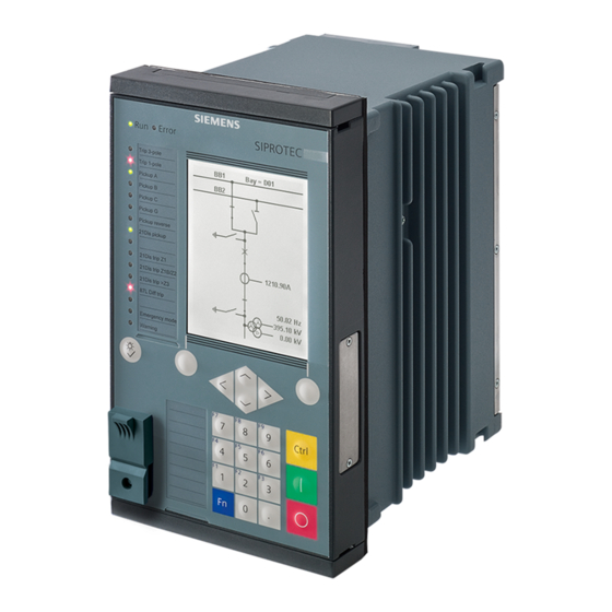
Forms of Devices and On-Site Operation Panels 2.1 Flush-Mounting Devices Flush-Mounting Devices Description 2.1.1 The flush-mounting devices were conceived for installation in 19-inch racks or special openings in control desks and cabinets. The on-site operation panel is linked permanently to the device. Base Module [le_surface_mounting_front, 2, --_--] Figure 2-1... - Page 21 Forms of Devices and On-Site Operation Panels 2.1 Flush-Mounting Devices [le_rear modular device, 1, --_--] Figure 2-2 Rear View of a Modular Device, Terminals of a Typical Device with IO202 Current terminal 1A Spring clip Voltage terminal 1B Voltage terminal 1C Voltage terminal 1D Protective grounding terminal Plug-in module position F...
- Page 22 Forms of Devices and On-Site Operation Panels 2.1 Flush-Mounting Devices [le_rear non modular, 1, --_--] Figure 2-3 Rear View of a Non-Modular Device (7xx82), Terminals of a Typical Device with IO102 Current terminal A Spring clip Voltage terminal B Voltage terminal D Voltage terminal L Time synchronization G Plug-in module position E...
- Page 23 Forms of Devices and On-Site Operation Panels 2.1 Flush-Mounting Devices Fastening Openings of the Base and 1/3 Module To remove the screw covers, introduce the screwdriver into the provided slot. [dw_screwdriver, 1, --_--] Figure 2-4 Slot for Introducing the Screwdriver Loosen the cover by turning slightly.
- Page 24 Forms of Devices and On-Site Operation Panels 2.1 Flush-Mounting Devices Expansion Module [le_front expansion module, 1, --_--] Figure 2-6 Front View of the Expansion Module Device housing On-site operation panel Bus terminal for an additional expansion module (shown with bus termination plate) Unused bus terminals are sealed with a cover.
- Page 25 Forms of Devices and On-Site Operation Panels 2.1 Flush-Mounting Devices [le_rear expansion module, 1, --_--] Figure 2-7 Rear View of the Expansion Module Current terminal xA Spring clip Voltage terminal xB Bus terminal to the base module Voltage terminal xC Voltage terminal xD Protective grounding terminal NOTE...
- Page 26 Forms of Devices and On-Site Operation Panels 2.1 Flush-Mounting Devices Counting Method for Assemblies in 19-Inch Rack (View of the Rear of the Device) [dwbgrpos-170713-01.tif, 3, en_US] Figure 2-8 Counting Method for Assemblies in 19-Inch Rack (Example) Current terminal A Voltage terminal A, B, C, D Terminal for time synchronization G Plug-in module E, F...
- Page 27 Forms of Devices and On-Site Operation Panels 2.1 Flush-Mounting Devices NOTE The structure of the 2nd device row is described in chapter 5.2.1.3 Expanding Devices with 2nd Device Row. Connection Systems [le_connection, 1, --_--] Figure 2-9 Connection Systems Cut-out for contact tab Contact tab (prefitted on the expansion module) Hinged angle clip Snap-in spring...
-
Page 28: Surface-Mounted Devices With Integrated On-Site Operation Panel
Forms of Devices and On-Site Operation Panels 2.2 Surface-Mounted Devices with Integrated On-Site Operation Panel Surface-Mounted Devices with Integrated On-Site Operation Panel Description of the Modular Device 2.2.1 NOTE The basic device structure is described in chapter 2.1.1 Description The surface-mounting devices with integrated on-site operation panel were conceived for fitting on a flat wall surface. - Page 29 Forms of Devices and On-Site Operation Panels 2.2 Surface-Mounted Devices with Integrated On-Site Operation Panel [dwauzeil-040211-01.tif, 2, --_--] Figure 2-11 Basic and Expansion Module of the Surface-Mounting Device Mounting bracket NOTE When a base module is expanded, 2 mounting brackets must be fitted between the on-site operation panels and the distance frame.
-
Page 30: Description Of The Non-Modular Surface-Mounting Device
Forms of Devices and On-Site Operation Panels 2.2 Surface-Mounted Devices with Integrated On-Site Operation Panel Fastening Openings [dwbaaube-040211-01.tif, 2, --_--] Figure 2-12 Fastening Openings of the Base Module Top fastening openings Bottom fastening openings 2.2.2 Description of the Non-Modular Surface-Mounting Device NOTE The basic device structure is described in chapter 2.1.1 Description... - Page 31 Forms of Devices and On-Site Operation Panels 2.2 Surface-Mounted Devices with Integrated On-Site Operation Panel [le_device with console above and below, 1, --_--] Figure 2-13 Bracket with the Opening Upward (Left) and the Opening Downward (Right) Flush-mounting device Bracket for the surface-mounting variant Bracket opening for cable entry or exit when mounting or dismantling the device SIPROTEC 5, Hardware Description, Manual C53000-G5040-C002-C, Edition 10.2017...
- Page 32 Forms of Devices and On-Site Operation Panels 2.2 Surface-Mounted Devices with Integrated On-Site Operation Panel [sc device mounting, 2, --_--] Figure 2-14 Surface-Mounting Version of the Non-Modular Device, Mounted SIPROTEC 5, Hardware Description, Manual C53000-G5040-C002-C, Edition 10.2017...
- Page 33 Forms of Devices and On-Site Operation Panels 2.2 Surface-Mounted Devices with Integrated On-Site Operation Panel Fastening Openings [sc fixing console, 2, --_--] Figure 2-15 Fastening Openings of the Bracket SIPROTEC 5, Hardware Description, Manual C53000-G5040-C002-C, Edition 10.2017...
-
Page 34: Surface-Mounted Devices With Detached On-Site Operation Panel
Forms of Devices and On-Site Operation Panels 2.3 Surface-Mounted Devices with Detached On-Site Operation Panel Surface-Mounted Devices with Detached On-Site Operation Panel Description 2.3.1 NOTE The basic device structure is described in chapter 2.1.1 Description The surface-mounting devices with detached on-site operation panel are a variant of the surface-mounting devices with an integrated on-site operation panel. - Page 35 Forms of Devices and On-Site Operation Panels 2.3 Surface-Mounted Devices with Detached On-Site Operation Panel Rear plate of the on-site operation panel Connecting cable between the base module and the on-site operation panel Fastening Openings [dwbaaube-040211-01.tif, 2, --_--] Figure 2-17 Device Structure of the Base Module Top fastening openings Bottom fastening openings...
- Page 36 Forms of Devices and On-Site Operation Panels 2.3 Surface-Mounted Devices with Detached On-Site Operation Panel [dwosobb1-040211-01.tif, 2, --_--] Figure 2-18 Fastening Openings for the On-Site Operation Panel Screw cover (pull towards you to remove) Fastening opening Fastening opening with fastening screw SIPROTEC 5, Hardware Description, Manual C53000-G5040-C002-C, Edition 10.2017...
-
Page 37: On-Site Operation Panels
Forms of Devices and On-Site Operation Panels 2.4 On-Site Operation Panels On-Site Operation Panels Description 2.4.1 Operating Concept The operating concept is based on 4 groups: • Navigation in the menu tree • Modification of settings • Display of measured values and protocols •... -
Page 38: Overview Of Operating Elements And Display Elements
Forms of Devices and On-Site Operation Panels 2.4 On-Site Operation Panels [dw_osop_with_pushbutton, 2, --_--] Figure 2-20 Variants 1/6 Views Overview of Operating Elements and Display Elements 2.4.2 On-Site Operation Panel of the Base 1/3 Module [le_base_module, 1, --_--] Figure 2-21 Base 1/3 Module in Standard, US, and China Design Operating state display Display in 2 design versions... - Page 39 Forms of Devices and On-Site Operation Panels 2.4 On-Site Operation Panels The on-site operation panels are distinguished by the following characteristics: • Flat and compact design • LCD (Liquid Crystal Display) graphics display Small with 192 x 128 pixels for showing measured values and small control displays Large with 240 x 320 pixels for showing measured values and control displays •...
- Page 40 Forms of Devices and On-Site Operation Panels 2.4 On-Site Operation Panels Operating Element/ Function Display Element USB port with protective cover Type B for notebook/PC 16 two-colored parameterizable LEDs On-Site Operation Panel of Expansion Modules [le_expansion modules, 1, --_--] Figure 2-22 Expansion Module 16 monochrome LEDs Cover labels...
- Page 41 Forms of Devices and On-Site Operation Panels 2.4 On-Site Operation Panels • Decorative film • 2 key switches for setting the operating mode Besides the base module, you can add an expansion module with key switches. The following table explains the meanings of the switch positions.
- Page 42 SIPROTEC 5, Hardware Description, Manual C53000-G5040-C002-C, Edition 10.2017...
-
Page 43: Electronic Modules
Electronic Modules Power-Supply Modules of the Modular Devices Input and Output Modules of the Modular Devices Power-Supply Module of Non-Modular Devices (7xx82) Input and Output Modules of the Non-Modular Devices (7xx82) SIPROTEC 5, Hardware Description, Manual C53000-G5040-C002-C, Edition 10.2017... -
Page 44: Power-Supply Modules Of The Modular Devices
Electronic Modules 3.1 Power-Supply Modules of the Modular Devices Power-Supply Modules of the Modular Devices Application Sheet of the Power-Supply Modules of the Modular Devices 3.1.1 Module Designation Function Description • PS201 Power-supply module • 24 V DC/48 V DC or DC 60 V to DC 250 V and AC 100 V to AC 230 V •... -
Page 45: Terminals
Electronic Modules 3.1 Power-Supply Modules of the Modular Devices 3.1.2.2 Terminals Overview of Terminals [le_ps201, 1, --_--] Figure 3-1 PS201 – Terminals Voltage terminal 2B Time synchronization G Detached on-site operation panel H Plug-in module position E Integrated Ethernet interface J COM link K, connection to the CB202 PCB assembly (plug-in module assembly), position K Plug-in module position F Protective grounding terminal... - Page 46 Electronic Modules 3.1 Power-Supply Modules of the Modular Devices Terminal and Connection Diagram [cdps201x-270912-01.tif, 1, en_US] Figure 3-2 PS201 – Terminal Diagram SIPROTEC 5, Hardware Description, Manual C53000-G5040-C002-C, Edition 10.2017...
- Page 47 Electronic Modules 3.1 Power-Supply Modules of the Modular Devices [tdps201x-270812-01.tif, 1, en_US] Figure 3-3 PS201 – Connection Diagram Time-Synchronization Terminal The terminal for time synchronization is located on the D-sub 9 interface (position G). Time synchronization signals for DC 5 V, DC 12 V, and DC 24 V can be processed as an option. For further information on connecting to the time synchronization, see chapter 6.6 Communication Interfaces in the Technical Data.
-
Page 48: Power-Supply Module Ps203
Electronic Modules 3.1 Power-Supply Modules of the Modular Devices Ethernet COM Link The Ethernet connection to the CB202 PCB assembly (plug-in module assembly with integrated power supply) is realized using the RJ45 interface. The RJ45 interface can be used exclusively for the connection of the CB202 module. This terminal is left unused when no CB202 module is in use. -
Page 49: Terminals
Electronic Modules 3.1 Power-Supply Modules of the Modular Devices 3.1.3.2 Terminals Overview of Terminals [le_ps203, 1, --_--] Figure 3-4 PS203 – Terminals 2-pole terminal to connect power supply LED: Power On Protective grounding terminal Connection Diagram [tdps203x-030713-01.tif, 2, en_US] Figure 3-5 PS203 –... - Page 50 Electronic Modules 3.1 Power-Supply Modules of the Modular Devices [dwkl2pol-030211-01.tif, 1, --_--] Figure 3-6 Connection of External Power Supply NOTE When expanding a device with the 2nd device row, you must install the connecting cable for the 2nd device row together with the associated angle rail. All required components are included with a power- supply module PS203.
-
Page 51: Plug-In Module Assembly With Integrated Power Supply Cb202
Electronic Modules 3.1 Power-Supply Modules of the Modular Devices Device bus of the outermost right expansion module of the 1st device row Sealing plate Adaptor angle 2 fastening screws [dw_schiene-020414-01, 1, --_--] Figure 3-9 Angle Rail Angle rail 2 rubber seals Plug-In Module Assembly with Integrated Power Supply CB202 3.1.4 3.1.4.1... -
Page 52: Terminals
Electronic Modules 3.1 Power-Supply Modules of the Modular Devices LEDs of the RJ45 Terminals The light-emitting diodes (LEDs) signal the operating state of the communication connection. The operating states are explained in the following table: COM Link (RJ45) Signal Color Operating State LED 1 CL2_LED0_N Yellow Flashes when a communication module is inserted in... - Page 53 Electronic Modules 3.1 Power-Supply Modules of the Modular Devices Connection Diagram [tdcb202x-100713-01.tif, 2, en_US] Figure 3-11 CB202 – Connection Diagram [dwkl2pol-030211-01.tif, 1, --_--] Figure 3-12 Connection of External Power Supply SIPROTEC 5, Hardware Description, Manual C53000-G5040-C002-C, Edition 10.2017...
-
Page 54: Input And Output Modules Of The Modular Devices
Electronic Modules 3.2 Input and Output Modules of the Modular Devices Input and Output Modules of the Modular Devices Function Description of the Input and Output Modules of the Modular Devices 3.2.1 Module Designation Function Description • IO201 Input and output module •... -
Page 55: Input And Output Module Io201
Electronic Modules 3.2 Input and Output Modules of the Modular Devices Input and Output Module IO201 3.2.2 3.2.2.1 Description The terminals for the following are located on the input and output module IO201: • 4 current transformers (optionally protection-class current transformers or instrument transformers) •... - Page 56 Electronic Modules 3.2 Input and Output Modules of the Modular Devices NOTE x corresponds to the slot in the 19-inch rack. Terminal and Connection Diagram For the binary inputs and outputs, the x corresponds to the slot in the 19-inch rack. [cdio201x-290812-01.tif, 1, en_US] Figure 3-14 IO201 –...
-
Page 57: Input And Output Module Io202
Electronic Modules 3.2 Input and Output Modules of the Modular Devices [tdio201x-290812-01.tif, 1, en_US] Figure 3-15 IO201 – Connection Diagram 3.2.3 Input and Output Module IO202 3.2.3.1 Description This input and output module is used as the base measurement module in all protection devices and bay units. One device can contain several IO202 input and output modules. -
Page 58: Terminals
Electronic Modules 3.2 Input and Output Modules of the Modular Devices 3.2.3.2 Terminals Overview of Terminals [dwio202p-030211-01.tif, 2, --_--] Figure 3-16 IO202 – Terminals Current terminal xA Voltage terminal xB Voltage terminal xC Voltage terminal xD Protective grounding terminal NOTE x corresponds to the slot in the 19-inch rack. - Page 59 Electronic Modules 3.2 Input and Output Modules of the Modular Devices Terminal and Connection Diagram For the binary inputs and outputs, the x corresponds to the slot in the 19-inch rack. [cdio202x-300812-01.tif, 1, en_US] Figure 3-17 IO202 – Terminal Diagram SIPROTEC 5, Hardware Description, Manual C53000-G5040-C002-C, Edition 10.2017...
-
Page 60: Input And Output Module Io203
Electronic Modules 3.2 Input and Output Modules of the Modular Devices [tdio202x-240812-01.tif, 1, en_US] Figure 3-18 IO202 – Connection Diagram Input and Output Module IO203 3.2.4 3.2.4.1 Description The terminals for the following are located on the input and output module IO203: •... -
Page 61: Terminals
Electronic Modules 3.2 Input and Output Modules of the Modular Devices 3.2.4.2 Terminals Overview of Terminals [le_io203, 1, --_--] Figure 3-19 IO203 – Terminals Current terminal xA Current terminal xB Voltage terminal xD Protective grounding terminal NOTE x corresponds to the slot in the 19-inch rack. SIPROTEC 5, Hardware Description, Manual C53000-G5040-C002-C, Edition 10.2017... - Page 62 Electronic Modules 3.2 Input and Output Modules of the Modular Devices Terminal and Connection Diagram For the binary inputs and outputs, the x corresponds to the slot in the 19-inch rack. [cdio203x-280812-01.tif, 1, en_US] Figure 3-20 IO203 – Terminal Diagram SIPROTEC 5, Hardware Description, Manual C53000-G5040-C002-C, Edition 10.2017...
-
Page 63: Input And Output Module Io204
Electronic Modules 3.2 Input and Output Modules of the Modular Devices [tdio203x-110313-01.tif, 1, en_US] Figure 3-21 IO203 – Connection Diagram Input and Output Module IO204 3.2.5 3.2.5.1 Description The terminals for the following are located on the input and output module IO204: •... -
Page 64: Terminals
Electronic Modules 3.2 Input and Output Modules of the Modular Devices 3.2.5.2 Terminals Overview of Terminals [dwio204p-201112-01.tif, 2, --_--] Figure 3-22 IO204 – Terminals Voltage terminal xA Voltage terminal xC Voltage terminal xD Protective grounding terminal NOTE x corresponds to the slot in the 19-inch rack. SIPROTEC 5, Hardware Description, Manual C53000-G5040-C002-C, Edition 10.2017... - Page 65 Electronic Modules 3.2 Input and Output Modules of the Modular Devices Terminal and Connection Diagram For the binary inputs and outputs, the x corresponds to the slot in the 19-inch rack. [cdio204x-201112-01.tif, 1, en_US] Figure 3-23 IO204 – Terminal Diagram SIPROTEC 5, Hardware Description, Manual C53000-G5040-C002-C, Edition 10.2017...
-
Page 66: Input And Output Module Io205
Electronic Modules 3.2 Input and Output Modules of the Modular Devices [tdio204x-201112-01.tif, 1, en_US] Figure 3-24 IO204 – Connection Diagram Input and Output Module IO205 3.2.6 Description 3.2.6.1 The terminals for the following are located on the input and output module IO205: •... -
Page 67: Terminals
Electronic Modules 3.2 Input and Output Modules of the Modular Devices 3.2.6.2 Terminals Overview of Terminals [dwio205p-030211-01.tif, 2, --_--] Figure 3-25 IO205 – Terminals Voltage terminal xA Voltage terminal xB Voltage terminal xC Voltage terminal xD Protective grounding terminal NOTE x corresponds to the slot in the 19-inch rack. - Page 68 Electronic Modules 3.2 Input and Output Modules of the Modular Devices Terminal and Connection Diagram For the binary inputs and outputs, the x corresponds to the slot in the 19-inch rack. [cdio205x-260213-01.tif, 1, en_US] Figure 3-26 IO205 – Terminal Diagram SIPROTEC 5, Hardware Description, Manual C53000-G5040-C002-C, Edition 10.2017...
-
Page 69: Input And Output Module Io206
Electronic Modules 3.2 Input and Output Modules of the Modular Devices [tdio205x-240812-01.tif, 1, en_US] Figure 3-27 IO205 – Connection Diagram Input and Output Module IO206 3.2.7 3.2.7.1 Description The terminals for the following are located on the input and output module IO206: •... -
Page 70: Terminals
Electronic Modules 3.2 Input and Output Modules of the Modular Devices 3.2.7.2 Terminals Overview of Terminals [dwio206p-030211-01.tif, 2, --_--] Figure 3-28 IO206 – Terminals Voltage terminal xA Voltage terminal xD Protective grounding terminal NOTE x corresponds to the slot in the 19-inch rack. SIPROTEC 5, Hardware Description, Manual C53000-G5040-C002-C, Edition 10.2017... - Page 71 Electronic Modules 3.2 Input and Output Modules of the Modular Devices Terminal and Connection Diagram For the binary inputs and outputs, the x corresponds to the slot in the 19-inch rack. [cdio206x-280812-01.tif, 1, en_US] Figure 3-29 IO206 – Terminal Diagram [tdio206x-050313-02.tif, 1, en_US] Figure 3-30 IO206 –...
-
Page 72: Input And Output Module Io207
Electronic Modules 3.2 Input and Output Modules of the Modular Devices Input and Output Module IO207 3.2.8 3.2.8.1 Description The terminals for the following are located on the input and output module IO207: • 16 binary inputs • 8 binary outputs with 8 standard make contacts (type S) The connections are distributed over four 14-pole voltage terminals. - Page 73 Electronic Modules 3.2 Input and Output Modules of the Modular Devices Terminal and Connection Diagram For the binary inputs and outputs, the x corresponds to the slot in the 19-inch rack. [cdio207x-260213-01.tif, 1, en_US] Figure 3-32 IO207 – Terminal Diagram SIPROTEC 5, Hardware Description, Manual C53000-G5040-C002-C, Edition 10.2017...
-
Page 74: Input And Output Module Io208
Electronic Modules 3.2 Input and Output Modules of the Modular Devices [tdio207x-300812-01.tif, 1, en_US] Figure 3-33 IO207 – Connection Diagram Input and Output Module IO208 3.2.9 3.2.9.1 Description The terminals for the following are located on the input and output module IO208: •... -
Page 75: Terminals
Electronic Modules 3.2 Input and Output Modules of the Modular Devices 3.2.9.2 Terminals Overview of Terminals [dwio208p-030211-01.tif, 2, --_--] Figure 3-34 IO208 – Terminals Current terminal xA Voltage terminal xB Voltage terminal xC Voltage terminal xD Protective grounding terminal x corresponds to the slot in the 19-inch rack. SIPROTEC 5, Hardware Description, Manual C53000-G5040-C002-C, Edition 10.2017... - Page 76 Electronic Modules 3.2 Input and Output Modules of the Modular Devices Terminal and Connection Diagram For the binary inputs and outputs, the x corresponds to the slot in the 19-inch rack. [cdio208x-050313-01.tif, 3, en_US] Figure 3-35 IO208 – Terminal Diagram SIPROTEC 5, Hardware Description, Manual C53000-G5040-C002-C, Edition 10.2017...
-
Page 77: Input And Output Module Io209
Electronic Modules 3.2 Input and Output Modules of the Modular Devices [tdio208x-300812-01.tif, 1, en_US] Figure 3-36 IO208 – Connection Diagram 3.2.10 Input and Output Module IO209 3.2.10.1 Description The terminals for the following are located on the input and output module IO209: •... -
Page 78: Terminals
Electronic Modules 3.2 Input and Output Modules of the Modular Devices 3.2.10.2 Terminals Overview of Terminals [dwio209p-030211-01.tif, 2, --_--] Figure 3-37 IO209 – Terminals Voltage terminal xA Voltage terminal xC Voltage terminal xD Protective grounding terminal NOTE x corresponds to the slot in the 19-inch rack. SIPROTEC 5, Hardware Description, Manual C53000-G5040-C002-C, Edition 10.2017... - Page 79 Electronic Modules 3.2 Input and Output Modules of the Modular Devices Terminal and Connection Diagram For the binary inputs and outputs, the x corresponds to the slot in the 19-inch rack. [cdio209x-110313-01.tif, 1, en_US] Figure 3-38 IO209 – Terminal Diagram SIPROTEC 5, Hardware Description, Manual C53000-G5040-C002-C, Edition 10.2017...
-
Page 80: Input And Output Module Io210
Electronic Modules 3.2 Input and Output Modules of the Modular Devices [tdio209x-270812-01.tif, 1, en_US] Figure 3-39 IO209 – Connection Diagram Input and Output Module IO210 3.2.11 3.2.11.1 Description The terminals for the following are located on the input and output module IO210: •... -
Page 81: Terminals
Electronic Modules 3.2 Input and Output Modules of the Modular Devices 3.2.11.2 Terminals Overview of Terminals [dwio202p-030211-01.tif, 2, --_--] Figure 3-40 IO210 – Terminals Current terminal xA Voltage terminal xB Voltage terminal xC Voltage terminal xD Protective grounding terminal NOTE x corresponds to the slot in the 19-inch rack. - Page 82 Electronic Modules 3.2 Input and Output Modules of the Modular Devices Terminal and Connection Diagram For the binary inputs and outputs, the x corresponds to the slot in the 19-inch rack. [cd_io210, 2, en_US] Figure 3-41 IO210 – Terminal Diagram Voltage input MT3 with higher voltage immunity (maximum continuous voltage ±...
-
Page 83: Input And Output Module Io211
Electronic Modules 3.2 Input and Output Modules of the Modular Devices [td_io210, 2, en_US] Figure 3-42 IO210 – Connection Diagram 3.2.12 Input and Output Module IO211 3.2.12.1 Description The terminals for the following are located on the input and output module IO211: •... -
Page 84: Terminals
Electronic Modules 3.2 Input and Output Modules of the Modular Devices 3.2.12.2 Terminals Overview of Terminals [dwio211p-211112-01.tif, 2, --_--] Figure 3-43 IO211 Terminals Voltage terminal xA Voltage terminal xC Voltage terminal xD Protective grounding terminal NOTE x corresponds to the slot in the 19-inch rack. SIPROTEC 5, Hardware Description, Manual C53000-G5040-C002-C, Edition 10.2017... - Page 85 Electronic Modules 3.2 Input and Output Modules of the Modular Devices Terminal and Connection Diagram For the binary inputs and outputs, the x corresponds to the slot in the 19-inch rack. [cdio211x-221112-01.tif, 1, en_US] Figure 3-44 IO211 Terminal Diagram SIPROTEC 5, Hardware Description, Manual C53000-G5040-C002-C, Edition 10.2017...
-
Page 86: Input And Output Module Io212
Electronic Modules 3.2 Input and Output Modules of the Modular Devices [tdio211x-211112-01.tif, 1, en_US] Figure 3-45 IO211 Connection Diagram Input and Output Module IO212 3.2.13 3.2.13.1 Description The terminals for the following are located on the input and output module IO212: •... -
Page 87: Terminals
Electronic Modules 3.2 Input and Output Modules of the Modular Devices 3.2.13.2 Terminals Overview of Terminals [dwio204p-201112-01.tif, 2, --_--] Figure 3-46 IO212 – Terminals Voltage terminal xA Voltage terminal xC Voltage terminal xD Protective grounding terminal NOTE x corresponds to the slot in the 19-inch rack. SIPROTEC 5, Hardware Description, Manual C53000-G5040-C002-C, Edition 10.2017... - Page 88 Electronic Modules 3.2 Input and Output Modules of the Modular Devices Terminal and Connection Diagram For the binary inputs and outputs, the x corresponds to the slot in the 19-inch rack. [cd_io212, 1, en_US] Figure 3-47 IO212 – Terminal Diagram SIPROTEC 5, Hardware Description, Manual C53000-G5040-C002-C, Edition 10.2017...
-
Page 89: Input And Output Module Io214
Electronic Modules 3.2 Input and Output Modules of the Modular Devices [tdio212x, 1, en_US] Figure 3-48 IO212 – Connection Diagram Input and Output Module IO214 3.2.14 3.2.14.1 Description This input and output module is used as the base measurement module in all protection devices. One device can contain several IO214 input and output modules. -
Page 90: Terminals
Electronic Modules 3.2 Input and Output Modules of the Modular Devices 3.2.14.2 Terminals Overview of Terminals [dwio214p-030211-01.tif, 2, --_--] Figure 3-49 IO214 – Terminals Current terminal xA Voltage terminal xB Voltage terminal xC Voltage terminal xD Protective grounding terminal NOTE x corresponds to the slot in the 19-inch rack. - Page 91 Electronic Modules 3.2 Input and Output Modules of the Modular Devices Terminal and Connection Diagram For the binary inputs and outputs, the x corresponds to the slot in the 19-inch rack. [cdio214x-260213-01.tif, 1, en_US] Figure 3-50 IO214 – Terminal Diagram SIPROTEC 5, Hardware Description, Manual C53000-G5040-C002-C, Edition 10.2017...
-
Page 92: Input And Output Module Io215
Electronic Modules 3.2 Input and Output Modules of the Modular Devices [tdio214x-270812-01.tif, 1, en_US] Figure 3-51 IO214 – Connection Diagram 3.2.15 Input and Output Module IO215 3.2.15.1 Description This input and output module is used as the base measurement module in all protection devices and bay units. One device can contain several IO215 input and output modules. -
Page 93: Input Module Io230
Electronic Modules 3.2 Input and Output Modules of the Modular Devices Input Module IO230 3.2.16 3.2.16.1 Description The terminals for the following are located on the IO230 module: • 48 binary inputs The connections are distributed over six 10-pole connection terminals. NOTE Note that the IO230 input module has group switching for switching thresholds. - Page 94 Electronic Modules 3.2 Input and Output Modules of the Modular Devices NOTE x corresponds to the slot in the 19-inch rack. Terminal and Connection Diagram NOTE The polarities of the voltages at the binary inputs must not be reversed! [cdio230x-030713-01.tif, 1, en_US] Figure 3-53 IO230 –...
- Page 95 Electronic Modules 3.2 Input and Output Modules of the Modular Devices [tdio230x, 1, en_US] Figure 3-54 IO230 – Connection Diagram SIPROTEC 5, Hardware Description, Manual C53000-G5040-C002-C, Edition 10.2017...
-
Page 96: Input And Output Module Io231
Electronic Modules 3.2 Input and Output Modules of the Modular Devices Input and Output Module IO231 3.2.17 3.2.17.1 Description The terminals for the following are located on the input and output module IO231: • 24 binary inputs • 24 binary outputs, standard make contacts (type S) The connections are distributed over six 10-pole connection terminals. - Page 97 Electronic Modules 3.2 Input and Output Modules of the Modular Devices Terminal and Connection Diagram NOTE The polarities of the voltages at the binary inputs must not be reversed! [cd_io231x, 2, en_US] Figure 3-56 IO231 – Terminal Diagram SIPROTEC 5, Hardware Description, Manual C53000-G5040-C002-C, Edition 10.2017...
-
Page 98: Input Module Io233
Electronic Modules 3.2 Input and Output Modules of the Modular Devices [td_tdio231x, 1, en_US] Figure 3-57 IO231 – Connection Diagram 3.2.18 Input Module IO233 3.2.18.1 Description The terminals for the following are located on the input module IO233: • 48 binary inputs SIPROTEC 5, Hardware Description, Manual C53000-G5040-C002-C, Edition 10.2017... -
Page 99: Terminals
Electronic Modules 3.2 Input and Output Modules of the Modular Devices The connections are distributed over six 10-pole terminals. 3.2.18.2 Terminals Overview of Terminals [dw_io233x, 1, en_US] Figure 3-58 IO233 – Terminals Terminal xA Terminal xC Terminal xD Protective grounding terminal Terminal xH Terminal xG Terminal xE... - Page 100 Electronic Modules 3.2 Input and Output Modules of the Modular Devices [cd_io233x, 1, en_US] Figure 3-59 IO233 – Terminal Diagram SIPROTEC 5, Hardware Description, Manual C53000-G5040-C002-C, Edition 10.2017...
-
Page 101: Input And Output Module Pb201
Electronic Modules 3.2 Input and Output Modules of the Modular Devices [td_io233x, 1, en_US] Figure 3-60 IO233 – Connection Diagram 3.2.19 Input and Output Module PB201 3.2.19.1 Description The process-bus assembly is used for the reception of Sampled Measured Values (SMV) according to IEC 61850-9-2 via 6 optical interfaces. -
Page 102: Terminals
Electronic Modules 3.2 Input and Output Modules of the Modular Devices 3.2.19.2 Terminals Overview of Terminals [dw_pb201, 2, --_--] Figure 3-61 PB201 – Terminals 2 duplex LC interfaces channel A 2 duplex LC interfaces channel B 2 duplex LC interfaces channel C 1 duplex LC interface service port 2 protective grounding terminals Product code... - Page 103 Electronic Modules 3.2 Input and Output Modules of the Modular Devices Optical budget Minimum 7.5 dB for 50 μm/125 μm, NA = 0.2 Minimum 11.0 dB for 62.5 μm/125 μm, NA = 0.275 Laser class 1 as per EN 60825-1/-2 With the use of 62.5 μm/125 μm and 50 μm/125 μm optical fibers Comment: Numerical aperture (NA = sin θ...
-
Page 104: Power-Supply Module Of Non-Modular Devices (7Xx82)
Electronic Modules 3.3 Power-Supply Module of Non-Modular Devices (7xx82) Power-Supply Module of Non-Modular Devices (7xx82) Power-Supply Module PS101 3.3.1 3.3.1.1 Description The power-supply module PS101 is always permanently installed in the 1/3 module. The following can be found on the PS101 module: •... -
Page 105: Terminals
Electronic Modules 3.3 Power-Supply Module of Non-Modular Devices (7xx82) 3.3.1.2 Terminals Overview of Terminals The terminals assigned to the module are identified by the frame in the figure. [le_ps101, 1, --_--] Figure 3-62 PS101 – Terminals Voltage terminal L Time synchronization G Plug-in module position E Plug-in module position F Integrated Ethernet interface J... - Page 106 Electronic Modules 3.3 Power-Supply Module of Non-Modular Devices (7xx82) Terminal and Connection Diagram [cdps101x-210513-01.tif, 1, en_US] Figure 3-63 PS101 – Terminal Diagram [tdps101x-210513-01.tif, 1, en_US] Figure 3-64 PS101 – Connection Diagram Time-Synchronization Terminal The terminal for time synchronization is located on the D-sub 9 interface (position G). Time synchronization signals for DC 5 V, DC 12 V, and DC 24 V can be processed as an option.
- Page 107 Electronic Modules 3.3 Power-Supply Module of Non-Modular Devices (7xx82) For further information on connecting to the time synchronization, see chapter 6.6 Communication Interfaces in the Technical Data. Integrated Ethernet Interface (RJ45) This terminal is used to load the device with DIGSI 5 using Ethernet. This terminal also enables straight- forward IEC 61850 Ethernet communication (including GOOSE) or communication with another protocol via Ethernet, for example, for connecting an external RTD unit.
-
Page 108: Input And Output Modules Of The Non-Modular Devices (7Xx82)
Electronic Modules 3.4 Input and Output Modules of the Non-Modular Devices (7xx82) Input and Output Modules of the Non-Modular Devices (7xx82) Function Description of the Input and Output Modules of the Non-Modular 3.4.1 Devices Module Designation Function Description • IO101 Input and output module •... -
Page 109: Terminals
Electronic Modules 3.4 Input and Output Modules of the Non-Modular Devices (7xx82) 3.4.2.2 Terminals Overview of Terminals The terminals assigned to the module are identified by the frame in the figure. [le_io101, 1, --_--] Figure 3-65 IO101 – Terminals Current terminal A Voltage terminal B Voltage terminal D Protective grounding terminal... - Page 110 Electronic Modules 3.4 Input and Output Modules of the Non-Modular Devices (7xx82) Terminal and Connection Diagram [cdio101x-220513-01.tif, 1, en_US] Figure 3-66 IO101 – Terminal Diagram SIPROTEC 5, Hardware Description, Manual C53000-G5040-C002-C, Edition 10.2017...
-
Page 111: Input And Output Module Io102
Electronic Modules 3.4 Input and Output Modules of the Non-Modular Devices (7xx82) [tdio101x-220513-01.tif, 1, en_US] Figure 3-67 IO101 – Connection Diagram Input and Output Module IO102 3.4.3 3.4.3.1 Description The terminals for the following are located on the input and output module IO102: •... -
Page 112: Terminals
Electronic Modules 3.4 Input and Output Modules of the Non-Modular Devices (7xx82) 3.4.3.2 Terminals Overview of Terminals The terminals assigned to the module are identified by the frame in the figure. [le_io102, 1, --_--] Figure 3-68 IO102 – Terminals Current terminal A Voltage terminal B Voltage terminal D Protective grounding terminal... - Page 113 Electronic Modules 3.4 Input and Output Modules of the Non-Modular Devices (7xx82) Terminal and Connection Diagram [cdio102x-220513-01.tif, 1, en_US] Figure 3-69 IO102 – Terminal Diagram SIPROTEC 5, Hardware Description, Manual C53000-G5040-C002-C, Edition 10.2017...
-
Page 114: Input And Output Module Io103
Electronic Modules 3.4 Input and Output Modules of the Non-Modular Devices (7xx82) [tdio102x-220513-01.tif, 1, en_US] Figure 3-70 IO102 – Connection Diagram 3.4.4 Input and Output Module IO103 3.4.4.1 Description The terminals for the following are located on the input and output module IO103: •... -
Page 115: Terminals
Electronic Modules 3.4 Input and Output Modules of the Non-Modular Devices (7xx82) 3.4.4.2 Terminals Overview of Terminals The terminals assigned to the module are identified by the frame in the figure. [le_io103, 1, --_--] Figure 3-71 IO103 – Terminals Current terminal A Current terminal B Voltage terminal D Protective grounding terminal... - Page 116 Electronic Modules 3.4 Input and Output Modules of the Non-Modular Devices (7xx82) Terminal and Connection Diagram [cdio103x-131113-01, 3, en_US] Figure 3-72 IO103 – Terminal Diagram SIPROTEC 5, Hardware Description, Manual C53000-G5040-C002-C, Edition 10.2017...
-
Page 117: Input And Output Module Io110
Electronic Modules 3.4 Input and Output Modules of the Non-Modular Devices (7xx82) [tdio103x-01.vsd, 1, en_US] Figure 3-73 IO103 – Connection Diagram Input and Output Module IO110 3.4.5 3.4.5.1 Description The terminals for the following are located on the input and output module IO110: •... -
Page 118: Terminals
Electronic Modules 3.4 Input and Output Modules of the Non-Modular Devices (7xx82) 3.4.5.2 Terminals Overview of Terminals [le_io110, 1, --_--] Figure 3-74 IO110 – Terminals Terminal M Terminal N SIPROTEC 5, Hardware Description, Manual C53000-G5040-C002-C, Edition 10.2017... - Page 119 Electronic Modules 3.4 Input and Output Modules of the Non-Modular Devices (7xx82) Terminal and Connection Diagram [cdio110x-220513-01.tif, 2, en_US] Figure 3-75 IO110 – Terminal Diagram SIPROTEC 5, Hardware Description, Manual C53000-G5040-C002-C, Edition 10.2017...
-
Page 120: Input And Output Module Io111
Electronic Modules 3.4 Input and Output Modules of the Non-Modular Devices (7xx82) [tdio110x-220513-01.tif, 1, en_US] Figure 3-76 IO110 – Connection Diagram Input and Output Module IO111 3.4.6 3.4.6.1 Description The connections for the following are located on the input and output module IO111: •... -
Page 121: Terminals
Electronic Modules 3.4 Input and Output Modules of the Non-Modular Devices (7xx82) 3.4.6.2 Terminals Overview of Terminals [dw_io111, 1, --_--] Figure 3-77 IO111 – Connections Terminal M Terminal N SIPROTEC 5, Hardware Description, Manual C53000-G5040-C002-C, Edition 10.2017... - Page 122 Electronic Modules 3.4 Input and Output Modules of the Non-Modular Devices (7xx82) Terminal and Connection Diagram [cd_io111, 1, en_US] Figure 3-78 IO111 – Terminal Diagram SIPROTEC 5, Hardware Description, Manual C53000-G5040-C002-C, Edition 10.2017...
-
Page 123: Connections Of Temperature Sensors And Cables
Connections of Temperature Sensors and Cables Connections of Temperature Sensors Directly to the Device It is possible in principle to connect temperature sensors with 2-phase or 3-phase technology. To achieve the specified accuracy, Siemens recommends only using 3-phase technology. [dw_example_temp_sensor_3phase, 1, en_US] Figure 3-80... - Page 124 Electronic Modules 3.4 Input and Output Modules of the Non-Modular Devices (7xx82) [dw_example_temp_sensor_2phase, 1, en_US] Figure 3-81 Example: Connecting Temperature Sensors RTD 1 (2-Line Terminal) and RTD 2 (2-Line Terminal) to Terminals M1 to M5 [dw_temperature_sensor, 1, en_US] Figure 3-82 Example: Connecting Temperature Sensors RTD 1 (3-Line Terminal) and RTD 2 (2-Line Terminal) to Terminals M1 to M5 Connecting the Lines...
- Page 125 Electronic Modules 3.4 Input and Output Modules of the Non-Modular Devices (7xx82) Loosen the 2 screws for fastening the shielding plates on the device next to the 16-pole or 17-pole plug ² so that there is somewhat more than 2 mm (0.08 in) space. Push the prepared shielding plate under the screw heads and tighten them.
- Page 126 SIPROTEC 5, Hardware Description, Manual C53000-G5040-C002-C, Edition 10.2017...
-
Page 127: Plug-In Modules
Plug-In Modules Function Description of Plug-In Modules of Modular and Non-Modular Devices Communication Modules Measuring-Transducer Modules SIPROTEC 5, Hardware Description, Manual C53000-G5040-C002-C, Edition 10.2017... -
Page 128: Function Description Of Plug-In Modules Of Modular And Non-Modular Devices
Plug-In Modules 4.1 Function Description of Plug-In Modules of Modular and Non-Modular Devices Function Description of Plug-In Modules of Modular and Non- Modular Devices Plug-In Module Function Description Designation USART-xx-yEL Serial communication module with electric transmission USART-xx-yFO Serial communication module with optical transmission for short distance USART-xx-yLDFO Serial communication module with optical transmission for long distance ETH-xx-2EL... -
Page 129: Communication Modules
Plug-In Modules 4.2 Communication Modules Communication Modules Overview 4.2.1 SIPROTEC devices can be ordered with factory-installed communication modules. The communication modules can also be installed and replaced in the SIPROTEC devices afterwards. You do not have to open the device for this. - Page 130 Plug-In Modules 4.2 Communication Modules Time synchronization G Plug-in module position E Detached on-site operation panel H Plug-in module position F Integrated Ethernet interface J Connection to the expansion module with CB202 module Protective grounding terminal [dwlmnppo-030211-01.tif, 2, --_--] Figure 4-2 Plug-In Module Positions and Communication Terminals in the Expansion Module with CB202 2-pole terminal to connect power supply COM link L (connection to interface K of the base unit)
- Page 131 Plug-In Modules 4.2 Communication Modules [le_slots and communication terminals, 1, --_--] Figure 4-3 Plug-In Module Positions and Communication Terminals on the 1/3 Module, for Non-Modular Devices (7xx82) Time synchronization G Plug-in module position E Plug-in module position F Integrated Ethernet interface J Protective grounding terminal The following communication modules can be used for SIPROTEC 5: •...
-
Page 132: Communication Applications Of The Plug-In Modules
Plug-In Modules 4.2 Communication Modules • Ethernet Modules Application: Ethernet-based communication to the substation automation technology via substation- control protocols (for example, IEC 61850 and DNP3) – Secure communication to DIGSI 5 – Communication between the devices (IEC 61850-GOOSE) – Synchrophasor protocol The modules can be operated with or without an integrated switch. - Page 133 Plug-In Modules 4.2 Communication Modules Plug-In Module 2 x optical serial, 820 nm, ST connector, ● 2 km via 62.5/125 μm multimode optical fiber 2 x electrical Ethernet 100 Mbit/s, RJ45, ● 20 m 2 x optical Ethernet 100 Mbit/s, ●...
- Page 134 Plug-In Modules 4.2 Communication Modules Plug-In Module 2 x optical serial, bidirectional via ● 1 common optical fiber, 1550 nm/ 1300 nm (Tx/Rx), 2 x simplex LC plugs, 40 km via 9/125 μm singlemode optical fiber Applications DIGSI 5 Protocol ●...
-
Page 135: Serial Modules For Short Distances
The RS485 interface in devices of the SIPROTEC 4 series is a D-Sub 9 connection with a connected terminal resistor. If you connect devices from the SIPROTEC 5 series with devices from the SIPROTEC 4 series, then use a Y adaptor with the order designation 7XV5103-2BA00. Complete the connection on the last device with a terminal resistor. -
Page 136: Usart-Ab-1El
Plug-In Modules 4.2 Communication Modules The preceding figure shows the cabling using the new RJ45 sockets in a simplified format. The serial RS485 bus can be extended by simply connecting Ethernet patch cables from device to device. [dwserma2-030211-05.tif, 1, en_US] Figure 4-6 Redundant Communication with 2 Masters Using RS485 Bus (for Example, Redundant IEC 60870-5-103 Protocol) -
Page 137: Usart-Ac-2El
Plug-In Modules 4.2 Communication Modules 4.2.3.3 USART-AC-2EL Description Serial asynchronous communication module with 2 independent elec- trical interfaces Product code P1Zxxxxxxxxxx Figure Connector type 4 x RJ45 Baud rate 1.2 kbits/s to 115.2 kbits/s For 1 or 2 protocols or applications IEC 60870-5-103 (1 application per connection) DNP3... -
Page 138: Usart-Ae-2Fo
Plug-In Modules 4.2 Communication Modules Laser class 1 as per EN 60825-1/-2 With the use of 62.5 μm/125 μm and 50 μm/125 μm optical fibers Comment: Numerical aperture (NA = sin θ (launch angle)) 4.2.3.5 USART-AE-2FO Description Serial asynchronous or synchronous communication module with 2 independent optical interfaces Product code P1Zxxxxxxxxxx... -
Page 139: Usart-Af-1Ldfo
Plug-In Modules 4.2 Communication Modules The attainable distance in multimode optical fibers is limited by 2 factors. • Bandwidth length product Typical for 62.5 μm/125 μm optical fibers: 400 MHz x km to 800 MHz x km Typical for 50 μm/125 μm optical fibers: 400 MHz x km to 1200 MHz x km •... - Page 140 Plug-In Modules 4.2 Communication Modules Figure Connector type 1 x duplex LC Wavelength λ = 1300 nm Baud rate 2 Mbit/s for the protection-interface communication Protocol Protection-interface communication Max. line length 60 km for singlemode optical fibers or 8 km with multimode optical fiber Distance 8 km Laser class 1 as per EN 60825-1/-2 With the use of 62.5 μm/125 μm and 50 μm/125 μm optical fibers...
-
Page 141: Usart-Ah-1Ldfo
Plug-In Modules 4.2 Communication Modules NOTE If you use the module USART-AG-1LDFO for distances under 25 km, connect 2 attenuators 7XV5107-0AA00. To continue using the Duplex LC plugs, attach both attenuators at one end of the remote connection (see Figure 4-7). -
Page 142: Usart-Ak-1Ldfo
Plug-In Modules 4.2 Communication Modules Figure Connector type 1 x LC Simplex Wavelength λ = 1550 nm Baud rate 2 Mbit/s for the protection-interface communication Protocol Protection-interface communication Max. line length 40 km for singlemode optical fibers Distance 40 km Laser class 1 as per EN 60825-1/-2 With the use of 9 μm/125 μm optical fibers Minimum... -
Page 143: Usart-Aw-2Ldfo
Plug-In Modules 4.2 Communication Modules NOTE If you use the protection-interface module USART-AK-1LDFO for distances under 50 km, then connect 2 attenuators 7XV5107-0AA00. To continue using the Duplex LC plugs, attach both attenuators at one end of the remote connection (see Figure 4-7). -
Page 144: Usart-Ax-2Ldfo
Plug-In Modules 4.2 Communication Modules Figure Connector type 2 x duplex LC Wavelength λ = 1300 nm Baud rate 2 Mbit/s for the protection-interface communication Protocol Protection-interface communication Max. line length 60 km for singlemode optical fibers or 8 km with multimode optical fiber Distance 8 km Laser class 1 as per EN 60825-1/-2 With the use of 62.5 μm/125 μm and 50 μm/125 μm optical fibers... -
Page 145: Usart-Ay-2Ldfo
Plug-In Modules 4.2 Communication Modules Description Protection-interface module for synchronous or asynchronous operation with 2 optical interfaces In particular, a bidirectional data exchange through a single optical fiber is possible with the USART-AY-2LDFO module. Product code P1Zxxxxxxxxxx Figure Connector type 2 x LC Simplex Wavelength λ... -
Page 146: Usart-Av-2Ldfo
Operation of Ethernet Modules The Ethernet modules of the SIPROTEC 5 series can be operated optionally with or without integrated switch function. This applies for the electrical as well as the optical module. This function can be selected via the SIPROTEC 5, Hardware Description, Manual C53000-G5040-C002-C, Edition 10.2017... - Page 147 EN100 modules of the SIPROTEC 4 series. If the RSTP protocol or the HSR protocol is active, the optical modules of the SIPROTEC 4 series and the SIPROTEC 5 series can be operated in a ring. When using SIPROTEC 4 devices with module firmware ≤ V4.05 and SIPROTEC 5 devices, the maximum allow- able number of participants is 30 devices.
-
Page 148: Eth-Ba-2El
Plug-In Modules 4.2 Communication Modules [dwethsw3-090713-01.tif, 2, en_US] Figure 4-9 Operation of Ethernet Modules Without Integrated Switch Function with Single or Redundant Connection to the Switch 4.2.5.2 ETH-BA-2EL Description Communication module for the transmission of Ethernet protocols via 2 electrical interfaces Product code P1Zxxxxxxxxxx Figure... -
Page 149: Eth-Bb-2Fo
Plug-In Modules 4.2 Communication Modules 4.2.5.3 ETH-BB-2FO Description Communication module for the transmission of Ethernet protocols via 2 optical interfaces Product code P1Zxxxxxxxxxx Figure Connector type 2 x duplex LC Wavelength λ = 1300 nm Baud rate 100 Mbit/s Protocol DIGSI 5 protocol (secure Web service protocol) IEC 61850 (MMS and GOOSE) DNP3... -
Page 150: Measuring-Transducer Modules
Plug-In Modules 4.3 Measuring-Transducer Modules Measuring-Transducer Modules Overview 4.3.1 You can install the measuring-transducer modules in base modules or 1/3 modules (plug-in module positions E and F) and in expansion modules with a CB202 module (plug-in module position M, N, or P). ANAI-CA-4EL 4.3.2 The ports CH1 to CH4 of the measuring-transducer modules are Safety Extra Low Voltage circuits (SELV... -
Page 151: Arc-Cd-3Fo
Pulse duration connection test 11 μs Comment: All values in combination with sensors approved by Siemens. Numerical aperture (NA = sin θ (launch angle)) NOTE Laser class 1 is maintained in compliance with EN 60825-1 and EN 60825-2 when using 1 mm polymer optical fibers. - Page 152 SIPROTEC 5, Hardware Description, Manual C53000-G5040-C002-C, Edition 10.2017...
-
Page 153: Working On The Device
Working on the Device First Steps Expanding Modular Devices Plug-In Modules Arc Sensors for Module: ARC-CD-3FO Battery SDHC Memory Card Installing Current and Voltage Terminals SIPROTEC 5, Hardware Description, Manual C53000-G5040-C002-C, Edition 10.2017... -
Page 154: First Steps
Join several on-site operation panels to one another with firm contact. ² Siemens recommends the use of contact washers on painted metal mounting walls. If the mounting wall is not metallic, place a metal layer, for example a metal sheet, between the mounting wall and the on- site operation panels. - Page 155 Working on the Device 5.1 First Steps Safety Notes DANGER Danger during electrical inspection Noncompliance with the safety notes will result in death, severe injury or considerable material damage. Comply with all given safety notes when carrying out the electrical inspection. ²...
-
Page 156: Expanding Modular Devices
Working on the Device 5.2 Expanding Modular Devices Expanding Modular Devices Flush-Mounting Devices 5.2.1 5.2.1.1 Basic Rules for Expansion NOTE Prepare the following tools for the device expansion: • Phillips screwdriver size PZ1 and PZ2 • Screwdriver DIN 4 x 0.8 •... -
Page 157: Expanding 1St Device Row
Working on the Device 5.2 Expanding Modular Devices 5.2.1.2 Expanding 1st Device Row Preparation NOTE Reordered modules are not contained in the original device configuration. Use DIGSI to perform the corre- sponding extension in the Hardware and Protocols Editor. Carry out the steps described in this chapter if you wish to expand an installed device later on with expan- sion modules. -
Page 158: Expanding Devices With 2Nd Device Row
Working on the Device 5.2 Expanding Modular Devices 5.2.1.3 Expanding Devices with 2nd Device Row Preparation NOTE Reordered modules are not contained in the original device configuration. Use DIGSI to perform the corre- sponding extension in the Hardware and Protocols Editor. Carry out the steps described in this chapter if you want to expand an installed device later on with a 2nd device row. - Page 159 Working on the Device 5.2 Expanding Modular Devices [dw_2zauba-020414-01, 2, --_--] Figure 5-2 Expansion with 2nd Device Row Extreme right expansion module of the 1st device row Connecting cable 2nd device row [dw_schiene-020414-01, 1, --_--] Figure 5-3 Angle Rail Angle rail 2 Rubber seals [dw_winkel-020414-01, 1, --_--] Figure 5-4...
-
Page 160: Surface-Mounted Devices With Integrated On-Site Operation Panel
Working on the Device 5.2 Expanding Modular Devices Adaptor angle 2 mounting screws Installation and Commissioning Reinstall the plastic screw covers. ² Refasten the terminal blocks and the necessary communication lines. ² Connect the current and voltage blocks of the expansion module. ²... -
Page 161: Expanding 1St Device Row
Working on the Device 5.2 Expanding Modular Devices [dwauize1-040211-01.tif, 2, --_--] Figure 5-5 Device Row Distance frame Mounting bracket Distance frame on base module rotated by 180 5.2.2.2 Expanding 1st Device Row Preparation NOTE Reordered modules are not contained in the original device configuration. Use DIGSI to perform the corre- sponding extension in the Hardware and Protocols Editor. - Page 162 Working on the Device 5.2 Expanding Modular Devices Remove the device completely. ² Assembling the On-Site Operation Panel into One Block [dwaublo1-040211-01.tif, 2, --_--] Figure 5-6 On-Site Operation Panel Fitted on Mounting Bracket Place the 2 mounting brackets intended for expansion in parallel to one another on a flat surface. ²...
-
Page 163: Expanding Devices With 2Nd Device Row
Working on the Device 5.2 Expanding Modular Devices Fit the device back onto the wall without fastened on-site operation panels. ² Use the supplied grounding cable to connect the expansion module with the device and reconnect the ² device to service ground. Fasten the connecting cable for the on-site operation panel on the extreme left-hand operation panel of ²... - Page 164 Working on the Device 5.2 Expanding Modular Devices NOTE The distance between the 1st and the 2nd device row must be not more than 80 mm (3.15 in). Install the 2nd device row. ² Unscrew the captive screws from the handle mold. ²...
-
Page 165: Surface-Mounted Devices With Detached On-Site Operation Panel
Working on the Device 5.2 Expanding Modular Devices Sealing plate Device bus of the outermost left expansion module of the 1st device row Installation and Commissioning Reinstall the plastic screw covers. ² Refasten the terminal blocks and the necessary communication lines. ²... -
Page 166: Expanding 1St Device Row
Working on the Device 5.2 Expanding Modular Devices [dwauizei-040211-01.tif, 1, --_--] Figure 5-9 Device Row [dwabosop-040211-01.vsd, 2, en_US] Figure 5-10 Detached On-Site Operation Panel 5.2.3.2 Expanding 1st Device Row Preparation NOTE Reordered modules are not contained in the original device configuration. Use DIGSI to perform the corre- sponding extension in the Hardware and Protocols Editor. - Page 167 Working on the Device 5.2 Expanding Modular Devices If you want to expand the device, then detach it completely. ² If you want to expand the on-site operation panel, then remove the on-site operation panel from the ² installation space. NOTE The device and the on-site operation panel can be expand independently of one another.
-
Page 168: Plug-In Modules
Working on the Device 5.3 Plug-In Modules Plug-In Modules Fasteners 5.3.1 The fasteners of the plug-in modules are shown in the following figure regarding the example of an installed module and an empty, covered slot. [le_fxing_elements, 1, --_--] Figure 5-11 Fasteners EMC spring contact Fastening screw... -
Page 169: Removing
Working on the Device 5.3 Plug-In Modules CAUTION Exercise caution with laser beams of the optical plug-in modules. Noncompliance with the safety notes can result in medium-severe or slight injuries. Do not look directly into the optical fiber terminals of the active optical plug-in modules, not even with ²... - Page 170 Working on the Device 5.3 Plug-In Modules Preparing Removal DANGER Risk of live voltage when removing the plug-in modules. Noncompliance with the safety notes will result death or severe injuries. Remove plug-in modules on the electrically deactivated device only. ² CAUTION Exercise caution with laser beams of the optical plug-in modules.
-
Page 171: Replacement
Working on the Device 5.3 Plug-In Modules Replacement 5.3.4 Preparing for Replacement DANGER Danger due to live voltage when replacing the plug-in modules. Noncompliance with the safety notes will result in death or severe injuries. Install plug-in modules on the electrically deactivated device only. ²... - Page 172 Working on the Device 5.3 Plug-In Modules NOTE If you have not cabled the optical fiber plug-in modules, then seal the terminals with protective covers. This prevents soiling of the terminals. SIPROTEC 5, Hardware Description, Manual C53000-G5040-C002-C, Edition 10.2017...
-
Page 173: Arc Sensors For Module: Arc-Cd-3Fo
Working on the Device 5.4 Arc Sensors for Module: ARC-CD-3FO Arc Sensors for Module: ARC-CD-3FO Point Sensor 5.4.1 5.4.1.1 Description The point sensor detects arcs in the control cabinets of the air-insulated system part. [dwsensap-210314-01, 2, en_US] Figure 5-12 Point Sensor for the Arc-Protection Module: ARC-CD-3FO Optically active zone Sensor head Supply line... -
Page 174: Installation
Working on the Device 5.4 Arc Sensors for Module: ARC-CD-3FO [dw_point_sensor_dimensions, 1, en_US] Figure 5-13 Dimensional Drawing of the Point Sensor The sensitivity of the point sensors with line lengths up to 4 m typically begins at 10 kLux. 5.4.1.2 Installation The point sensors are mounted in the different compartments of a control cabinet, see the following figure. - Page 175 As an alternative, you can also fasten the point sensor using a screw (M4). Tighten the screw with a ² torque of 0.2 Nm. Siemens recommends fastening the line to the wall below the point sensor. The line must not be bent or ² stressed in any other way.
-
Page 176: Line Sensor
In order to warrant safe functioning, the affected sensor must be substituted after detection of an arc. NOTE Hereby, Siemens declares that until now, UL has neither investigated whether the device can detect an arc- protection fault, neither if in case of an arc-protection fault, the safety of personnel and system is guaran- teed. - Page 177 Laser class 1 is maintained in compliance with EN 60825-1 and EN 60825-2 when using 1 mm polymer optical fibers. You need 2 holes (10.0 mm in diameter) in the control cabinet for fastening. Siemens recommends a ² distance of approx. 10 cm.
- Page 178 In order to warrant safe functioning, the affected sensor must be substituted after detection of an arc. NOTE Hereby, Siemens declares that until now, UL has neither investigated whether the device can detect an arc- protection fault, neither if in case of an arc-protection fault, the safety of personnel and system is guaran- teed.
-
Page 179: Battery
Working on the Device 5.5 Battery Battery Description 5.5.1 The battery lies in an externally accessible battery compartment. The battery compartment is located on the rear of the base module. You need not open the device when replacing the battery. If the auxiliary voltage fails, the battery ensures continued operation of the internal clock and storage of certain data (statistic values, values of thermal models) for at least 6 months. -
Page 180: Replacing The Battery
Working on the Device 5.5 Battery Replacing the Battery 5.5.2 Safety Notes NOTICE Exercise caution when replacing the battery. Noncompliance with the specified measures can result in material damage. Replace the battery only with the type specified in the Technical Data. ²... -
Page 181: Sdhc Memory Card
Reading the data of the SDHC memory card with a PC is not intended. Avoid too frequent insertion cycles! NOTE Use only the original SDHC memory card (ACCESAR) approved by Siemens for the 7KE85 fault recorder. Replacing the SDHC Memory Card De-energize the device. - Page 182 Working on the Device 5.6 SDHC Memory Card Push the holder, push the sealing cap to the back and remove it Unlock the eject lever Remove the SDHC memory card Unpack the new SDHC memory card. ² Do not touch the contacts of the SDHC memory card with your fingers. Insert the new SDHC memory card.
-
Page 183: Installing Current And Voltage Terminals
Working on the Device 5.7 Installing Current and Voltage Terminals Installing Current and Voltage Terminals Description 5.7.1 [dwklepos-030211-01.tif, 1, --_--] Figure 5-22 Current and Voltage Terminals with Spring Clips Current-terminal block Voltage-terminal block Spring clips The spring clips fix the terminal block in place. [sc_klepos-020414-01, 1, --_--] Figure 5-23 Voltage Terminal with Screw Connection... - Page 184 Working on the Device 5.7 Installing Current and Voltage Terminals Current-Terminal Block for Non-Modular Devices (7xx82) The following transformers can be installed optionally in a current-terminal block for non-modular devices: • 4 protection-class current transformers • 3 protection-class current transformers and 1 instrument transformer Protection-class current transformers on non-modular devices are transformers with a rated current of 1 A or 5 A and a measuring range of 50 x rated current.
-
Page 185: Connections Of Current Terminals
Stranded-wire conductor with bootlace ferrule • Solid conductor Siemens recommends the use of ring-type lugs with the dimensions shown in the following figure. Use copper cables only. The equivalent 50/60/16.7-Hz terminal is used as a re-orderable single part. SIPROTEC 5, Hardware Description, Manual... - Page 186 In order to maintain the insulation route, you must use insulated cable lugs or you must insulate the crimping zone (for example, by using heat-shrink tube insulation) Siemens recommends ring-type lugs of the PIDG series made by Tyco Electronics. Use copper conductors only, at least certified for a temperature of +105 °C. Use prepared solid conductors intended for single or multi-wiring connection, maximum 2 wires per pole, and for usage of ferrules, crimped- on pressure wire connectors (ring-type and pin-type).
-
Page 187: Connections Of Voltage Terminals
The single cable connection type is available for the connection. You can connect solid conductors as well as stranded-wire conductors with and without ferrules as single cables. Siemens recommends the use of twin ferrules of series PN 966 144 made by Tyco Electronics for the connection of 2 single cables. -
Page 188: Connections Of Voltage Terminals With Screw Connection
Working on the Device 5.7 Installing Current and Voltage Terminals Permissible tensile force for each connected 50 N following IEC 60947-1 (VDE 660, part 100) conductor 5.7.3.2 Connections of Voltage Terminals with Screw Connection For the connection of the following modules, Phoenix terminals are used (see Figure 5-23): •... -
Page 189: Technical Data
Technical Data Analog Inputs Supply Voltage Binary Inputs Relay Outputs Light-Emitting Diodes in the On-Site Operation Panel Communication Interfaces Electrical Tests Mechanical Tests Environmental Conditions 6.10 Operating Conditions 6.11 Reference Conditions and Influencing Variables 6.12 Approvals 6.13 Design Data 6.14 Assembly Dimensions 6.15 Modular Device Name Plate... -
Page 190: Analog Inputs
Technical Data 6.1 Analog Inputs Analog Inputs Current Inputs All current, voltage, and power data are specified as RMS values. Rated frequency f 50 Hz, 60 Hz rated 16.7 Hz (for rail protection devices only) Protection-class current trans- Rated current I Measuring range of Measuring range of the rated... - Page 191 1 pulse per second Pulse duration connection test 11 μs Comment: All values in combination with sensors approved by Siemens. Numerical aperture (NA = sin θ (launch angle)) High-Speed Measuring-Transducer Inputs, Voltage/Current (via IO210, IO212) NOTE Current and voltage must not be connected to a measuring-transducer input at the same time; only either current or voltage may be connected.
- Page 192 Technical Data 6.1 Analog Inputs Max. permissible voltage with 300 V respect to ground on the meas- uring inputs Permissible overload DC 20 V continuously DC 60 V continuously (IO210 MT3 terminal point C9) Measurement repetition 62.5 μs Insulation class IO210 ELV (Extra Low Voltage) (acc.
-
Page 193: Supply Voltage
Technical Data 6.2 Supply Voltage Supply Voltage Integrated Power Supply For modular devices, the following printed circuit-board assemblies have a power supply: PS201 – Power supply of the base module and of the 1st device row PS203 – Power supply of the 2nd device row CB202 –... - Page 194 Technical Data 6.2 Supply Voltage Integrated Power Supply Plug-in module for base < 5 W < 6 VA < 6 VA module or plug-in module assembly (for example, communication module) Stored-energy time for auxiliary voltage outage or For V ≥ DC 24 V ≥ 50 ms short circuit, modular devices For V ≥...
-
Page 195: Binary Inputs
Technical Data 6.3 Binary Inputs Binary Inputs Rated voltage range DC 24 V to 250 V The binary inputs of SIPROTEC 5 are bipolar with the exception of the binary inputs on the IO230, the IO231, and the IO233. Current consumption, excited Approx. -
Page 196: Relay Outputs
Technical Data 6.4 Relay Outputs Relay Outputs Standard Relay (Type S) Switching capacity On: 1000 W/VA Off: 30 VA; 40 W ohmic; 30 W/VA at L/R ≤ 40 ms AC and DC contact voltage 250 V Permissible current per contact (continuous) Permissible current per contact (switching on and 30 A for 1 s (make contact) holding) - Page 197 Technical Data 6.4 Relay Outputs High-Speed Relay with Semiconductor Acceleration (Type HS) Switching capacity On/Off: 1000 W/VA Contact voltage AC 200 V, DC 250 V Permissible current per contact (continuous) Permissible current per contact (switching on and 30 A for 1 s (make contact) holding) Short-time current across closed contact 250 A for 30 ms...
-
Page 198: Light-Emitting Diodes In The On-Site Operation Panel
Technical Data 6.5 Light-Emitting Diodes in the On-Site Operation Panel Light-Emitting Diodes in the On-Site Operation Panel Base Module Status Color Quantity Green ERROR Routable (adjustable with DIGSI 5) 2-colored: red or green Only the defined color can be used in operation. -
Page 199: Communication Interfaces
Technical Data 6.6 Communication Interfaces Communication Interfaces User Interface, Front Side You can find a USB connection of type B for the connection to a laptop computer or to a PC on the front side of the device. A protection cover protects this USB connection against pollution and humidity. User interface Connection USB type B... - Page 200 Technical Data 6.6 Communication Interfaces Signal Levels/ Signal Rated Input Voltage, DC Burdens 12 V 24 V 6.0 V 15.8 V 31.0 V IHigh 1.0 V at 1.4 V at 1.9 V at ILow = 0.25 mA = 0.25 mA = 0.25 mA ILow ILow...
- Page 201 Flashes when a communication module is inserted in plug-in module position N Table 6-5 Connection Signal Signal Description Siemens-specific assignment Connection using a special cable. Is part of the device delivery. Insulation class SELV (according to IEC 60255-27) Plug-In Modules...
-
Page 202: Electrical Tests
Technical Data 6.7 Electrical Tests Electrical Tests Standards IEC 60255 (product standard) IEEE Std C37.90 UL 508 Additional standards are listed for the individual tests. Installation Requirements Overvoltage category Degree of pollution Protection class Voltage-Immunity and Safety Tests Standards IEC 60255-27 Voltage test (routine test), current measurement inputs, voltage meas- AC 2.5 kV urement inputs, relay outputs... - Page 203 Technical Data 6.7 Electrical Tests Radiated electromagnetic field 20 V/m, 80 MHz/160 MHz/380 MHz/450 MHz/900 MHz immunity 10 V/1.85 GHz/2.15 GHz Spot frequencies 80 % AM IEC 61000-4-3 1 kHz Dwell time ≥ 10 s Electrical fast transient/ 4 kV burst immunity 5 ns/50 ns IEC 61000-4-4...
- Page 204 Technical Data 6.7 Electrical Tests Standard for Withstand Capability 20 V/m or Relay Systems to Radiated Elec- 80 MHz to 1 GHz tromagnetic Interference from Pulse modulation Transceivers (Keying test) IEEE Std C37.90.2 Ring wave immunity test 100 kHz (2.5 kV peak value) IEC 61000-4-12 Common-mode and differential-mode test Test duration ≥...
-
Page 205: Mechanical Tests
Technical Data 6.8 Mechanical Tests Mechanical Tests Vibration and Shock Stress in Stationary Use Standards IEC 60255-21 and IEC 60068 Vibration Test (sinusoidal) Sinusoidal 10 Hz to 60 Hz: ± 0.075 mm amplitude IEC 60255-21-1, class 2 60 Hz to 150 Hz; 10 m/s acceleration IEC 60068-2-6 Frequency sweep 1 octave/min... -
Page 206: Environmental Conditions
Technical Data 6.9 Environmental Conditions Environmental Conditions Temperatures Type test, in operation -25 °C to +85 °C (in compliance with IEC 60068-2-1 and IEC 60068-2-2, test Ad for 16 h and test Bd for 16 h) Temporarily permissible during operation (tested for -20 °C to +70 °C 96 h) Load conditions for the non-modular devices: With... - Page 207 Technical Data 6.9 Environmental Conditions Humidity Permissible humidity stress ≤ 75 % relative humidity on the annual average (according to IEC 60068-2-30) Up to 93 % relative humidity on 56 days a year Devices subjected to condensation are not to be oper- ated! Arrange the devices so that they are not exposed to direct sunlight or extreme temperature changes.
-
Page 208: Operating Conditions
The protection device is designed for flush mounting in conventional relay rooms and systems such that elec- tromagnetic compatibility (EMC) is ensured with proper flush mounting. Siemens additionally recommends: • Use contactors and relays that work within the same cabinet or the same relay panel with digital protec- tion equipment, only with suitable quenching equipment. -
Page 209: Reference Conditions And Influencing Variables
Technical Data 6.11 Reference Conditions and Influencing Variables 6.11 Reference Conditions and Influencing Variables Reference Conditions Measurand current I ± 1 % rated Measurand voltage V ± 1 % rated Frequency f ± 1 % rated Sine waveform, total harmonic distortion ≤... -
Page 210: Approvals
Technical Data 6.12 Approvals 6.12 Approvals UL-Listed/UL-Approved Base module and 1/3 base module IND. CONT. EQ. 69CA Expansion module IND. CONT. EQ. 69CA SIPROTEC 5, Hardware Description, Manual C53000-G5040-C002-C, Edition 10.2017... -
Page 211: Design Data
Technical Data 6.13 Design Data 6.13 Design Data Masses Device Size Weight of the Modular Devices Type of construction Flush-mounting device 4.4 kg 7.2 kg 9.9 kg 12.7 kg 15.5 kg Surface-mounted device with inte- 7.4 kg 11.7 kg 15.9 kg 20.2 kg 24.5 kg grated on-site operation panel... - Page 212 Technical Data 6.13 Design Data Type of Width over all x Height over all x Depth (in Inches) Construction (Maximum Dimensions) Surface- 150 mm x 225 mm x 300 mm x 375 mm x 450 mm x mounted device 314 mm x 314 mm x 314 mm x 314 mm x...
- Page 213 Technical Data 6.13 Design Data Tightening Torques for Terminal Screws Type of Line Current Terminal Voltage Terminal with Voltage Terminal with Spring-Loaded Terminals Screw Connection (also see Figure 5-22) (also see Figure 5-22) (also see Figure 5-23) Stranded wires with ring- 2.7 Nm No ring-type lug No ring-type lug...
-
Page 214: Assembly Dimensions
Technical Data 6.14 Assembly Dimensions 6.14 Assembly Dimensions Flush-Mounting Device [dw_z1_1-3, 2, en_US] Figure 6-1 Cut-Out Widths and Drilling Pattern – 1/3 Device, 1st Device Row SIPROTEC 5, Hardware Description, Manual C53000-G5040-C002-C, Edition 10.2017... - Page 215 Technical Data 6.14 Assembly Dimensions [dw_z1_1-2, 2, en_US] Figure 6-2 Cut-Out Widths and Drilling Pattern – 1/2 Device, 1st Device Row SIPROTEC 5, Hardware Description, Manual C53000-G5040-C002-C, Edition 10.2017...
- Page 216 Technical Data 6.14 Assembly Dimensions [dw_z1_2-3, 2, en_US] Figure 6-3 Cut-Out Widths and Drilling Pattern – 2/3 Device, 1st Device Row SIPROTEC 5, Hardware Description, Manual C53000-G5040-C002-C, Edition 10.2017...
- Page 217 Technical Data 6.14 Assembly Dimensions [dw_z1_5-6, 2, en_US] Figure 6-4 Cut-Out Widths and Drilling Pattern – 5/6 Device, 1st Device Row [dw_z1_1-1, 2, en_US] Figure 6-5 Cut-Out Widths and Drilling Pattern – 1/1 Device, 1st Device Row SIPROTEC 5, Hardware Description, Manual C53000-G5040-C002-C, Edition 10.2017...
- Page 218 Technical Data 6.14 Assembly Dimensions All drillings in the area of the specific device cut-out widths (see Table 6-6) must comply with the dimensions in the corresponding figures. [dw_z2_2-6, 2, en_US] Figure 6-6 Cut-Out Widths and Drilling Pattern – 1/3 Device, 2nd Device Row SIPROTEC 5, Hardware Description, Manual C53000-G5040-C002-C, Edition 10.2017...
- Page 219 Technical Data 6.14 Assembly Dimensions [dw_z2_3-6, 2, en_US] Figure 6-7 Cut-Out Widths and Drilling Pattern – 1/2 Device, 2nd Device Row [dw_z2_4-6, 2, en_US] Figure 6-8 Cut-Out Widths and Drilling Pattern – 2/3 Device, 2nd Device Row SIPROTEC 5, Hardware Description, Manual C53000-G5040-C002-C, Edition 10.2017...
- Page 220 Technical Data 6.14 Assembly Dimensions [dw_z2_5-6, 2, en_US] Figure 6-9 Cut-Out Widths and Drilling Pattern – 5/6 Device, 2nd Device Row [dw_z2_6-6, 2, en_US] Figure 6-10 Cut-Out Widths and Drilling Pattern – 1/1 Device, 2nd Device Row SIPROTEC 5, Hardware Description, Manual C53000-G5040-C002-C, Edition 10.2017...
- Page 221 Drilling Pattern – 1/1 Devices, 1st and 2nd Device Row Siemens recommends a drilling space of at least 55 mm (2.17 in) between the 1st and 2nd device row. Due to the connecting-cable length, the maximum space may be approx. 80 mm (3.15 in). The length of the cable is 890 mm (35.04 in) from the center of the plug to the center of the plug.
- Page 222 Technical Data 6.14 Assembly Dimensions Width of the Assembly Opening in mm (in Inches) 5/6 device (base module with 3 expansion modules) mm (14.61 +0.08 1/1 device (base module with 4 expansion modules) mm (17.56 +0.08 Table 6-7 Variable Housing Widths Dimension a Housing Widths in mm (in Inches) (Total Width: Housing Width + 4.6 mm (0.18 in))
- Page 223 Technical Data 6.14 Assembly Dimensions Surface-Mounted Devices with Integrated On-Site Operation Panel (Modular Device) [dwosopin-070211-01.tif, 2, en_US] Figure 6-14 1/3-Surface-Mounted Device with Integrated On-Site Operation Panel, Dimensions from the Side and Front Views NOTE For surface-mounted devices, make sure that the drillings fit for a screw of the size M6. SIPROTEC 5, Hardware Description, Manual C53000-G5040-C002-C, Edition 10.2017...
- Page 224 Technical Data 6.14 Assembly Dimensions [dwbohrge-1_3.vsd, 2, en_US] Figure 6-15 Drilling Pattern of a 1/3 Surface-Mounted Device – 1st Device Row [dwbohrge-1_2.vsd, 2, en_US] Figure 6-16 Drilling Pattern of a 1/2 Surface-Mounted Device – 1st Device Row SIPROTEC 5, Hardware Description, Manual C53000-G5040-C002-C, Edition 10.2017...
- Page 225 Technical Data 6.14 Assembly Dimensions [dwbohrge-2_3.vsd, 2, en_US] Figure 6-17 Drilling Pattern of a 2/3 Surface-Mounted Device – 1st Device Row [dwbohrge-5_6.vsd, 2, en_US] Figure 6-18 Drilling Pattern of a 5/6 Surface-Mounted Device – 1st Device Row SIPROTEC 5, Hardware Description, Manual C53000-G5040-C002-C, Edition 10.2017...
- Page 226 Technical Data 6.14 Assembly Dimensions [dwbohrge-070211-01.tif, 3, en_US] Figure 6-19 Drilling Pattern of a 1/1 Surface-Mounted Device – 1st Device Row [dw_z2_bohr_1-3.vsd, 2, en_US] Figure 6-20 Drilling Pattern of a 1/3 Surface-Mounted Device – 2nd Device Row SIPROTEC 5, Hardware Description, Manual C53000-G5040-C002-C, Edition 10.2017...
- Page 227 Technical Data 6.14 Assembly Dimensions [dw_z2_bohr_1-2.vsd, 2, en_US] Figure 6-21 Drilling Pattern of a 1/2 Surface-Mounted Device – 2nd Device Row [dw_z2_bohr_2-3.vsd, 2, en_US] Figure 6-22 Drilling Pattern of a 2/3 Surface-Mounted Device – 2nd Device Row SIPROTEC 5, Hardware Description, Manual C53000-G5040-C002-C, Edition 10.2017...
- Page 228 Technical Data 6.14 Assembly Dimensions [dw_z2_bohr_5-6.vsd, 2, en_US] Figure 6-23 Drilling Pattern of a 5/6 Surface-Mounted Device – 2nd Device Row SIPROTEC 5, Hardware Description, Manual C53000-G5040-C002-C, Edition 10.2017...
- Page 229 Technical Data 6.14 Assembly Dimensions [dw_z2_bohr_1-1.vsd, 2, en_US] Figure 6-24 Drilling Pattern of a 1/1 Surface-Mounted Device – 2nd Device Row SIPROTEC 5, Hardware Description, Manual C53000-G5040-C002-C, Edition 10.2017...
- Page 230 Technical Data 6.14 Assembly Dimensions Surface-Mounted Devices with Integrated On-Site Operation Panel (Non-Modular Device) [dw_console side view.vsd, 3, en_US] Figure 6-25 Non-Modular Surface-Mounted Device with Integrated On-Site Operation Panel, Dimensions from the Side and Front Views Surface-Mounted Devices with Integrated On-Site Operation Panel (Non-Modular Device) NOTE For surface-mounted devices, make sure that the drillings fit for a screw of the size M6.
- Page 231 Technical Data 6.14 Assembly Dimensions [dw_drilling non modular surface mounting with several consoles, 1, en_US] Figure 6-26 Drilling Pattern of a Non-Modular Surface-Mounted Device - Several Consoles The 149 mm are valid if several mounted consoles are to be mounted next to each other. Surface-Mounted Devices with Detached On-Site Operation Panel You can find more information on the drilling patterns for the devices in section Surface-Mounted Devices...
- Page 232 Technical Data 6.14 Assembly Dimensions [dw_z1_osop_1-2, 1, en_US] Figure 6-28 Drilling Pattern of the On-Site Operation Panel of the 1/2 Device [dw_z1_osop_2-3, 1, en_US] Figure 6-29 Drilling Pattern of the On-Site Operation Panel of the 2/3 Device SIPROTEC 5, Hardware Description, Manual C53000-G5040-C002-C, Edition 10.2017...
- Page 233 Technical Data 6.14 Assembly Dimensions [dw_z1_osop_5-6, 1, en_US] Figure 6-30 Drilling Pattern of the On-Site Operation Panel of the 5/6 Device [dw_z1_osop_1-1, 1, en_US] Figure 6-31 Drilling Pattern of the On-Site Operation Panel of the 1/1 Device SIPROTEC 5, Hardware Description, Manual C53000-G5040-C002-C, Edition 10.2017...
- Page 234 Technical Data 6.14 Assembly Dimensions [dwosopab-070211-01.tif, 2, en_US] Figure 6-32 Surface-Mounted Device with Detached On-Site Operation Panel, Dimensions in the Side and Front Views Refer to Table 6-7. for the variable dimension a. The drilling patterns correspond to the figures Figure 6-15 Figure 6-24.
-
Page 235: Modular Device Name Plate
Technical Data 6.15 Modular Device Name Plate 6.15 Modular Device Name Plate In the following table, the name plate of a modular device is explained as an example. The name plate is located on the device. 7SJ85 Device type or, in the case of expansion modules, designa- tion of the printed circuit board assembly Overcurrent Protection Product group... -
Page 236: Name Plate Of Non-Modular Devices (7Xx82)
Technical Data 6.16 Name Plate of Non-Modular Devices (7xx82) 6.16 Name Plate of Non-Modular Devices (7xx82) In the following table, the name plate of a non-modular device is explained as an example. The name plate is located on the device. 7SJ82 Device type Overcurrent Protection... -
Page 237: Name Plate, Ul Approval, Base Module And 1/3 Base Module
Technical Data 6.17 Name Plate, UL Approval, Base Module and 1/3 Base Module 6.17 Name Plate, UL Approval, Base Module and 1/3 Base Module UL approved for Canada and the USA IND. CONT. EQ. Industrial controller 69CA Approval number : max. 70 °C normal op. The ambient temperature must not exceed 70 °C or 158 °F Surr during normal operation. -
Page 238: Name Plate, Ul Approval, Expansion Module
The ambient temperature must not exceed 70 °C or 158 °F Surr during normal operation. Listed accessory for use with manufacturer´s Approved accessory for use with a protection device from protection relay. Siemens SIPROTEC 5, Hardware Description, Manual C53000-G5040-C002-C, Edition 10.2017... -
Page 239: Battery
Technical Data 6.19 Battery 6.19 Battery Type CR2032 Button cell Lithium Voltage Capacity 230 mAh Average service life of the battery, unpowered after removal of protec- At least 6 months tive film Service life of the battery in the activated state with protective film 10 years removed NOTE... -
Page 240: Sdhc Memory Card
Technical Data 6.20 SDHC Memory Card 6.20 SDHC Memory Card NOTE You can use only Siemens SDHC memory cards. Capacity 16 GB Performance class ≥ Class 10 Temperature range -40 °C to +85 °C Flash type Dimensions Width x Height x Depth (in Inches) SDHC memory card 24 mm x 32 mm x 2.1 mm (0.94 x 1.26 x 0.08) -
Page 241: Display Resolution
Technical Data 6.21 Display Resolution 6.21 Display Resolution LCD Graphic Display (Liquid Crystal Display) Small 192 x 128 pixels LCD Graphic Display (Liquid Crystal Display) Large 240 x 320 pixels SIPROTEC 5, Hardware Description, Manual C53000-G5040-C002-C, Edition 10.2017... - Page 242 SIPROTEC 5, Hardware Description, Manual C53000-G5040-C002-C, Edition 10.2017...
-
Page 243: Ordering Information
Ordering Information Ordering Spare Parts and Accessories SIPROTEC 5, Hardware Description, Manual C53000-G5040-C002-C, Edition 10.2017... -
Page 244: Ordering Spare Parts And Accessories
Ordering Information 7.1 Ordering Spare Parts and Accessories Ordering Spare Parts and Accessories Order Configurator and Order Options 7.1.1 Order Configurator The order configurator assists you in the selection of SIPROTEC 5 products. The order configurator is a Web application that can be used with any browser. The order configurator can be used to configure complete devices or individual components, such as communication modules, expansion modules, or other accessories. - Page 245 Ordering Information 7.1 Ordering Spare Parts and Accessories Group Accessories Terminal Type A current terminal, 3 x protection and 1 x measurement (for modular devices) Terminal Type A current terminal, 4 x measurement (for modular devices) Terminal Type B current terminal, 4 x protection (for non-modular devices) Terminal Type B current terminal, 3 x protection and 1 x measurement...
- Page 246 Ordering Information 7.1 Ordering Spare Parts and Accessories Group Accessories Sensors for arc protection Point sensor with line length of 15 m Sensors for arc protection Point sensor with line length of 20 m Sensors for arc protection Point sensor with line length of 35 m Sensors for arc protection Line sensor, length 3 m Sensors for arc protection...
-
Page 247: A Appendix
Appendix Hardware/Firmware Compatibility List SIPROTEC 5, Hardware Description, Manual C53000-G5040-C002-C, Edition 10.2017... -
Page 248: Hardware/Firmware Compatibility List
Appendix A.1 Hardware/Firmware Compatibility List Hardware/Firmware Compatibility List Component/ Product Feature Printed Circuit Board Assemblies CP100 ■ ■ ■ ■ ■ ■ ■ ■ PS101 ■ ■ ■ ■ ■ ■ ■ ■ IO101 ■ ■ ■ ■ ■ ■ ■... - Page 249 Appendix A.1 Hardware/Firmware Compatibility List Component/ Product Feature USART-AF-1LDFO ■ ■ ■ ■ ■ ■ ■ ■ ■ ■ ■ ■ USART-AG-1LDFO ■ ■ ■ ■ ■ ■ ■ ■ ■ ■ ■ ■ USART-AH-1LDFO ■ ■ ■ ■ ■ ■...
- Page 250 Appendix A.1 Hardware/Firmware Compatibility List Component/ Product Feature 4Z, 6F incl., TrAbb, only CBFP ■ ■ ■ ■ ■ Function Points I base ■ ■ ■ ■ ■ ■ ■ ■ ■ ■ ■ ■ Base + 10 function points ■...
-
Page 251: Glossary
Glossary Control display The control display becomes visible for devices with a large display after pressing the Control key. The diagram contains the switching devices to be controlled in the feeder. The control display serves for implementing switching operations. Specification of this diagram forms part of configuring. DCF77 The precise official time is determined in Germany by the Physikalisch-Technische Bundesanstalt PTB in Bruns- wick. - Page 252 SIPROTEC 5, Hardware Description, Manual C53000-G5040-C002-C, Edition 10.2017...
-
Page 253: Index
Index Activating the battery 154 Device structure Arc protection Base module 20 Installing the line sensor 176 Expansion module 24 Installing the point sensor 174 Dimensions 211, 240 Line sensor 176 Display elements 38 Plug-in module 151 Expansion module 40 Point sensor 173 On-site operation panel with push-button func- Assembly dimensions... - Page 254 Index LEDs 201 SDHC memory card Data 240 Replacement 181 Secure Digital High Capacity 181 Measuring-Transducer Module 150 Spring clip 183 Modular systems 17 Standards 202 Surface-mounted device with 2nd device row Expanding 163 Surface-mounted device with detached on-site operation panel 34 Expanding 165 On-site operation panel...