
Related Manuals for Protech Systems PA-6822


Summary of Contents for Protech Systems PA-6822
- Page 1 USER’S MANUAL PA-6822 15” POS Terminal ® ® Powered by Intel Celeron J1900 Quad-Core PA-6822...
- Page 2 CE NOTICE This is a class A product. In a domestic environment this product may cause radio interference in which case the user may be required to take adequate measures. PA-6822 Series User Manual Page 1...
- Page 3 WARNING! Some internal parts of the system may have high electrical voltage. And therefore we strongly recommend that qualified engineers can open and disassemble the system.The LCD and Touchscreen are easily breakable, please handle them with extra care. PA-6822 Series User Manual Page 2...
-
Page 4: Table Of Contents
Exploded Diagram for Printer…..………………………......Exploded Diagram for MSR & i-Button………..……………………… Exploded Diagram for 2 Display………………………....... Exploded Diagram for RFID…………………………………………… Exploded Diagram for HDD………………………........ Exploded Diagram for SSD……………………........APPENDIX A SYSTEM DISPLAY Installation of 8”/ 10.4” 2 Display..…………………………………... Page 3 PA-6822 SERIES USER MANUAL... -
Page 5: Chapter 1 Introduction
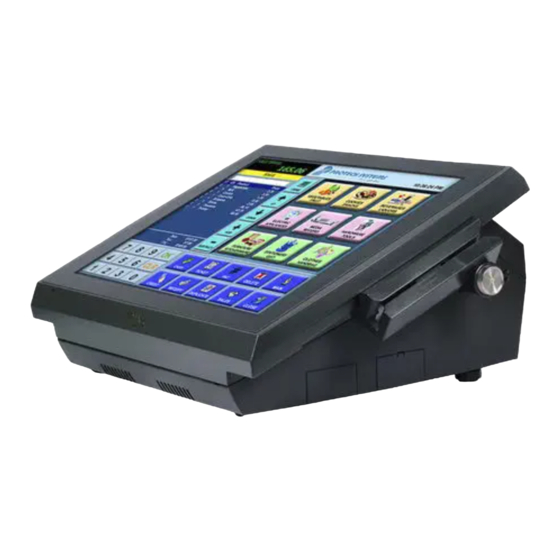
CHAPTER INTRODUCTION This chapter gives you the information for the PA-6822. It also outlines the system specifications. The following sections are included: About This Manual POS System Illustration System Specifications Safety Precautions Experienced users can jump to chapter 2 on page 17 for a quick start. - Page 6 Chapter 1 Introduction 1-1. ABOUT THIS MANUAL Thank you for purchasing our PA-6822 Series System. The PA-6822 is an updated system designed to be comparable with the highest performance of IBM AT personal computers. The PA-6822 provides faster processing speed, greater expandability and can handle more tasks than before.
-
Page 7: Pos System Illustration
Chapter 1 Introduction 1-2. POS SYSTEM ILLUSTRATION Top View Bottom View Front View Side View 24° 28° Unit: mm PA-6822 Series User Manual Page 6... - Page 8 Angle Adjustor Foot Power Button & Side USB (inside the shield) Ventilation Power NFC/RFID Hold Sensor Area VFD Customer Display (Optional) Open Button of Printer Door I/O Port Thermal Printer (inside the cover) (Optional) Unit: mm PA-6822 Series User Manual Page 7...
-
Page 9: System Specification
AMI SPI BIOS, 8 Mbits with VGA BIOS RTC Accuracy 3 days 3 seconds ± System Weight With power adapter approx. 8 kg Dimension (W x H x D) 390mm x 320mm x 190mm Viewing Angel 24~30° Certificate CE/FCC PA-6822 Series User Manual Page 8... - Page 10 IEC 61000-4-6 0.15~80MHz, 3Vrms, 80% AM, 1kHz IEC 61000-4-8 PFMF 50Hz, 1A/m IEC 61000-4-11 Voltage Dips > 95% reduction for 0.5 periods 30% reduction for 25 periods Voltage Interruptions > 95% reduction for 250 periods PA-6822 Series User Manual Page 9...
- Page 11 Brightness Resistive Touchscreen: Minimum Typical Maximum 160 cd/m 200 cd/m Projected Capacitive Touchscreen: Minimum Typical Maximum 180 cd/m 225 cd/m Environment Temperature Operating: 0~35°C (32 ~ 95°F) Storage: -20~60°C (-4 ~ 140°F) Humidity 20~90% PA-6822 Series User Manual Page 10...
- Page 12 7 dots Brightness: cd/m Dimensions: 107.2 18.2 3.75 0.55 0.75 6.75 Standard Code CP-437, CP-850, CP-857, CP-865, Katakana International Characters USA, FRANCE, GERMANY, UK, DENMARK I, SWDEN, ITALY, SPAIN, JAPAN, NORWAY, DENMARK II, RUSSIA, SLAVONIC PA-6822 Series User Manual Page 11...
- Page 13 3inch 72mm Paper width 2inch 58 +0/-1 mm; 3inch 80 +0/-1 mm -1 mm (Paper Width) D mm D mm A mm (Printing Width) 2 inch (A:54, C:58, D:2) 3 inch (A:72, C:80, D:4) PA-6822 Series User Manual Page 12...
- Page 14 CP-1251, CP-1252, CP-1253, CP-1254, CP-1257, Katakana KANJI JAPANESE (SHIFT-JIS) Code, TRADITIONAL CHINESE Code International Characters USA, FRANCE, GERMANY, UK, DENMARK I, SWDEN, ITALY, SPAIN I, JAPAN, NORWAY, DENMARK II, SPAIN II, LATIN AMERICA, KOREA, RUSSIA, SLAVONIC PA-6822 Series User Manual Page 13...
-
Page 15: Safety Precautions
Avoid exposure to sunlight for a long period of time (for example, in a closed car in summer time. Also avoid the system from any heating device.). Or do not use the PA-6822 when it has been left outdoors in a cold winter day. - Page 16 If heavy stains are present, moisten a cloth with diluted neutral washing agent or alcohol and then wipe thoroughly with a dry cloth. If dust is accumulated on the case surface, remove it by using a special vacuum cleaner for computers. PA-6822 Series User Manual Page 15...
-
Page 17: Chapter 2 System Configuration
Sections included: External I/O Port Pin Assignment How to Set Jumpers Component Locations & Jumper Settings Mainboard Printer Board (peripheral device) VFD Board (peripheral device) MSR Board (peripheral device) PA-6822 Series User Manual Page 16 Page 2-1... -
Page 18: System External I/O Port & Pin Assignment
2-1. SYSTEM EXTERNAL I/O PORT & PIN ASSIGNMENT Rear I/O COM(4) Display COM2 Power COM3 DRW1 USB3 DC IN Option1 Parallel Port (LPT, D-sub 25-pin) Option2 COM1 COM4 (2 x RS-232, D-sub 9-pin) Side I/O Power USB4 button PA-6822 Series User Manual Page 17... -
Page 19: Power Button
DC-IN Port DC IN: DC Power-In Port (rear IO) ASSIGNMENT ASSIGNMENT +24V +24V DC IN VGA Port VGA: VGA Port, D-Sub 15-pin (rear IO) ASSIGNMENT ASSIGNMENT GREEN BLUE DDCA DATA HSYNC VSYNC DDCA CLK PA-6822 Series User Manual Page 18... - Page 20 Right Side LED Yellow Color Blinking LAN Message Active No LAN Message Active Left Side LED Green Color On 10/100Mbps LAN Speed Indicator Orange Color on Giga LAN Speed Indicator No LAN switch/ hub connected. PA-6822 Series User Manual Page 19...
- Page 21 Close Write "00"h to I/O port "588"h USB Port USB0, USB1, USB2, USB3, USB4: USB Type A Ports USB0~3: Rear I/O USB4: Side IO USB0/ ASSIGNMENT ASSIGNMENT USB1/ +5V (Max. USB2/ current: 0.5A) USB4/ USB3 PA-6822 Series User Manual Page 20...
- Page 22 Chapter 2 System Configuration Printer Port (Optional) LPT: Printer Port, D-Sub 25-pin, co-lay with LPT1 ASSIGNMENT ASSIGNMENT STBJ ALFJ PDR0 ERRJ PDR1 PARR_INITJ PDR2 SLCTINJ PDR3 PDR4 PDR5 PDR6 PDR7 ACKJ BUSY SLCTJ PA-6822 Series User Manual Page 21...
-
Page 23: Main Board Component Locations & Jumper Settings
J1900 SATA1 Quad-Core JPWR_4P1 DIMM1 SATA2 JPWR_4P2 TOUCH3 USB6 JI_BUTTON1 Battery JP19 JP_VDD1 SPK1 JP32 SLOT1 JP15 SW1_3 JP14 JINV4 USB1 16 18 15 17 USB7 J3 JINVDRV1 LVDS1 COM4_2 PB-6822 Mainboard Component Locations PA-6822 Series User Manual Page 22... - Page 24 Chapter 2 System Configuration SLOT2 PB-6822 Mainboard Component Locations - Rear PA-6822 Series User Manual Page 23...
- Page 25 PIN1 & PIN2 to create one setting and shorting. You can either connect PIN2 & PIN3 to create another setting. The same jumper diagrams are applied all through this manual. The figure below shows what the manual diagrams look and what they represent. PA-6822 Series User Manual Page 24...
- Page 26 Chapter 2 System Configuration Jumper diagrams Jumper settings PA-6822 Series User Manual Page 25...
- Page 27 2. JP_COM1~4 are enabled when COM1~4 voltage adjustment is disabled on BIOS 3. Voltage of COM port is adjustable by BIOS or jumpers. Either way cannot be applied simultaneously in case of system error, component damage or serious boot failure. PS: COM4 is optional PA-6822 Series User Manual Page 26...
- Page 28 JP20, JP21, JP22: i-Button Function Connectors SELECTION JUMPER SETTING JUMPER ILLUSTRATION COM 3 JP20/JP21/JP22/ i-Button* JP20/JP21/JP22/ Note: Manufacturing Default is COM3. *COM3 & COM3-1 will not function when jumpers JP20, JP21 & JP22 are set as “i-Button.” PA-6822 Series User Manual Page 27...
- Page 29 Either way cannot be applied simultaneously in case of system error, component damage or serious boot failure. Cash Drawer Power Selection JP29: DRW1 SELECTION JUMPER SETTING JUMPER ILLUSTRATION JP29 +24V JP29 +12V Note: Manufacturing Default is open. PA-6822 Series User Manual Page 28...
-
Page 30: Usb Connector
Note: USB1 would be used when jumpers JP14 & JP15 are set as 1-2 (short) connected. LED Connector LED1-1: Power indication LED connector ASSIGNMENT PWR_LED LED1-1 Inverter Connector JINV4: Inverter connectors ASSIGNMENT +12V +12V JINV4 BRCTR LVDS_BKLTEN PA-6822 Series User Manual Page 29... -
Page 31: Power Connector
VCC12 DC5V_PWR1: DC 5Voltage Provider Connector ASSIGNMENT DC5V_PWR1 Power for Thermal Printer Connector PRT_PWR1: Power for Thermal Printer Connector ASSIGNMENT VCC24SB VCC24SB PRT_PWR1 External Speaker Connector SPK1: External speaker connector ASSIGNMENT SPK_GND SPK_OUT SPK1 PA-6822 Series User Manual Page 30... - Page 32 JP12 Note: Manufacturing Default is LED. LED Backlight Power Connector JINVDRV1: LED backlight power connector ASSIGNMENT JINVDRV1 Note: JINVDRV1 will not function when JP38 & JP39 are set as “RS-232” interface. PA-6822 Series User Manual Page 31...
- Page 33 JP9: 3-5, 4-6 (24 bit) 10.4” JP8: 3-5, 2-4 1024 x 768 JP9:3-5, 4-6 (18 bit) 10.4” JP8: 3-5, 4-6 800 x 600 JP9: 3-5, 4-6 (18bit) Note: Manufacturing Default is 15”, 1024 x 768 PA-6822 Series User Manual Page 32...
-
Page 34: Lvds Connector
Chapter 2 System Configuration LVDS Connector LVDS1: LVDS Connector ASSIGNMENT ASSIGNMENT LVDS_VCC LVDS_CLKA_D+ VDS_CLKA_D- LVDS1 LVDS_A2_D+ LVDS_A2_D- LVDS_B2_D- LVDS_B2_D+ LVDS_A1_D+ LVDS_A1_D- LVDS_B1_D- LVDS_B1_D+ LVDS_A0_D+ LVDS_B3_D+ LVDS_A0_D- LVDS_B3_D- LVDS_A3_D+ LVDS_B0_D+ LVDS_A3_D- LVDS_B0_D- LVDS_VCC LVDS_VCC PA-6822 Series User Manual Page 33... - Page 35 3. USB1 connector when JP14 & JP15 are set as 1-2 connected. Touch Panel Connector TOUCH3: Touch panel connectors ASSIGNMENT ASSIGNMENT LR (Low Right) UR (Up Right) LL (Low Left) UL (Up Left) Probe TOUCH3 PA-6822 Series User Manual Page 34...
-
Page 36: Printer Connector
After five to six seconds, set the jumper back to “Normal” and power-on the computer. Printer Connector LPT1: Printer connector LPT1 ASSIGNMENT ASSIGNMENT STBJ ALFJ PDR0 ERRJ PDR1 PAR_INITJ PDR2 SLCTINJ PDR3 PDR4 PDR5 PDR6 PDR7 ACKJ BUSY SLCTJ PA-6822 Series User Manual Page 35... - Page 37 JPWR_4P1, JPWR_4P2: Serial ATA power connectors ASSIGNMENT JPWR_4P1/ JPWR_4P2/ VCC12 Note: JPWR_4P1 only supports the optional RAID function on board. MSR/Card Reader Connector PS/2_2: MSR/Card reader connectors ASSIGNMENT KB_CLK (Output) KB_CLK_C (Input) KB_DATA_C (Input) KB_DATA (Output) PS/2_2 PA-6822 Series User Manual Page 36...
- Page 38 WAKE# +3.3V +1.5V SLOT1 Reserved SMB_CLK Reserved PETn2 +1.5V SMB_DATA CLKREQ# PETp2 Reserved Reserved REFCLK1- Reserved REFCLK1+ +3.3V Reserved +3.3V Reserved Reserved Reserved Reserved Reserved Reserved Reserved PERST# +1.5V PERn2 +3.3SB PERp2 Reserved +3.3V PA-6822 Series User Manual Page 37...
- Page 39 +1.5V Reserved SMB_CLK Reserved PETn0/SATA1_TX- +1.5V SMB_DATA CLKREQ# PETp0/SATA1_TX+ Reserved SLOT2 Reserved USB_D- REFCLK0- Reserved USB_D+ REFCLK0+ +3.3V Reserved +3.3V Reserved Reserved Reserved Reserved Reserved Reserved Reserved PERST# +1.5V PERn0/SATA1_RX+ +3.3SB PERp0/SATA1_RX- Reserved +3.3V PA-6822 Series User Manual Page 38...
-
Page 40: Printer Board Component Locations & Pin Assignment
Chapter 2 System Configuration 2-3. PRINTER BOARD COMPONENT LOCATIONS & PIN ASSIGNMENT Printer Board: PDAC-3100 PDAC-3100 Printer Board Component Locations PA-6822 Series User Manual Page 39... - Page 41 Chapter 2 System Configuration Power Supply Connector CN1: Power supply wafer ASSIGNMENT +24V +24V RS-232 Interface Connector CN7: RS-232 interface connector ASSIGNMENT ASSIGNMENT PA-6822 Series User Manual Page 40...
- Page 42 Auto-cutter motor drive signal 2A-2 Auto-cutter motor drive signal 1B-1 Auto-cutter motor drive signal 1B-2 Auto-cutter motor drive signal 1A-1 Auto-cutter motor drive signal 1A-2 Auto-cutter motor drive signal USB Connector CN8: USB Connector ASSIGNMENT ASSIGNMENT Vbus PA-6822 Series User Manual Page 41...
- Page 43 Head strobe signal DST3 Head strobe signal 3.3V Logic Power Thermistor GND Thermistor GND Thermistor signal Unused DST2 Head strobe signal DST1 Head strobe signal Head GND Head GND Head GND Head GND Head GND PA-6822 Series User Manual Page 42...
- Page 44 Power supply of the out-of- paper sensor GND of the platen position/ out-of-paper sensor Signal of the platen position sensor Unused Frame GND Frame GND Unused Motor drive signal Motor drive signal Motor drive signal Motor drive signal PA-6822 Series User Manual Page 43...
- Page 45 Feed signal RESET Reset signal Status signal Status signal Status signal Status signal Drawer sensor signal Drawer switch signal Drive terminal for the drawer (Vp side) GNDdu Drive terminal for the drawer (GND side) Unused PA-6822 Series User Manual Page 44...
- Page 46 Chapter 2 System Configuration Printer Board: MB-1030 CUT_CN1 COM1 9 10 USB_CN1 24V_CN1 PRINT_CN1 MB-1030 Printer Board Component Locations PA-6822 Series User Manual Page 45...
- Page 47 Chapter 2 System Configuration Power Supply Connector 24V_CN1: Power Supply Wafer ASSIGNMENT +24V +24V 24V_CN1 RS-232 Interface Connector COM1: RS-232 Interface Connector ASSIGNMENT ASSIGNMENT DSR /CTS 9 10 DTR /RTS COM1 PA-6822 Series User Manual Page 46...
- Page 48 Head strobe signal DST3 Head strobe signal 3.3V Logic Power Thermistor GND Thermistor GND Thermistor signal Unused DST2 Head strobe signal DST1 Head strobe signal Head GND Head GND Head GND Head GND Head GND PA-6822 Series User Manual Page 47...
- Page 49 Power supply of the out-of- paper sensor GND of the platen position/ out-of-paper sensor Signal of the platen position sensor Unused Frame GND Frame GND Unused Motor drive signal Motor drive signal Motor drive signal Motor drive signal PA-6822 Series User Manual Page 48...
- Page 50 Autocutter motor drive signal 1A-2 Autocutter motor drive signal Paper-Near-END Sensor Connector CN2: Paper-near-end sensor connector ASSIGNMENT FUNCTION Power supply of the near end sensor Signal of the near end sensor GND of the near end sensor PA-6822 Series User Manual Page 49...
- Page 51 Feed signal RESET Reset signal Status signal Status signal Status signal Status signal Drawer sensor signal Drawer switch signal Drive terminal for the drawer (Vp side) GNDdu Drive terminal for the drawer (GND side) Unused PA-6822 Series User Manual Page 50...
- Page 52 Chapter 2 System Configuration Printer Board: MB-1011 & MB-1013 MB-1013 MB-1011 MB-1011 & MB-1013 Printer Board Component Locations PA-6822 Series User Manual Page 51...
- Page 53 Chapter 2 System Configuration Power Supply Connector CN1: Power supply wafer ASSIGNMENT +24V +24V RS-232 Interface Connector CN7: RS-232 interface connector ASSIGNMENT ASSIGNMENT PA-6822 Series User Manual Page 52...
- Page 54 Head strobe signal DST3 Head strobe signal 3.3V Logic Power Thermistor GND Thermistor GND Thermistor signal Unused DST2 Head strobe signal DST1 Head strobe signal Head GND Head GND Head GND Head GND Head GND PA-6822 Series User Manual Page 53...
- Page 55 Power supply of the out-of- paper sensor GND of the platen position/ out-of-paper sensor Signal of the platen position sensor Unused Frame GND Frame GND Unused Motor drive signal Motor drive signal Motor drive signal Motor drive signal PA-6822 Series User Manual Page 54...
- Page 56 2A-2 Autocutter motor drive signal 1B-1 Autocutter motor drive signal 1B-2 Autocutter motor drive signal 1A-1 Autocutter motor drive signal 1A-2 Autocutter motor drive signal USB Interface Connector CN8: USB interface connector ASSIGNMENT Vbus PA-6822 Series User Manual Page 55...
- Page 57 Feed signal RESET Reset signal Status signal Status signal Status signal Status signal Drawer sensor signal Drawer switch signal Drive terminal for the drawer (Vp side) GNDdu Drive terminal for the drawer (GND side) Unused PA-6822 Series User Manual Page 56...
-
Page 58: Vfd Board Component Locations & Pin Assignment
Chapter 2 System Configuration 2-4. VFD BOARD COMPONENT LOCATIONS & PIN ASSIGNMENT VFD Board: MB-4103, LD720 JP12V MB-4103 & LD720 VFD Board Component Locations PA-6822 Series User Manual Page 57... - Page 59 Chapter 2 System Configuration Power Switch Selection JP12V: Power Switch Selection SELECTION JUMPER SETTING JUMPER ILLUSTRATION JP12V JP12V Note: Manufacturing Default is ON. RS-232 Serial Interface Connector CN1: RS-232 serial interface wafer ASSIGNMENT ASSIGNMENT +12V/+5V PA-6822 Series User Manual Page 58...
-
Page 60: Msr Board Component Locations & Pin Assignment
2-5. MSR BOARD COMPONENT LOCATIONS & PIN ASSIGN- MENT ID TECH ID-TECH MSR Board Component Locations Main Connector ASSIGNMENT ASSIGNMENT Chassis Ground K-CLK (Computer connections) P-CLK K-DATA (Keyboard connections) (Computer connections) P-DATA (Keyboard connections) +5V Vcc PA-6822 Series User Manual Page 59... - Page 61 Chapter 2 System Configuration SYSKING SYSKING MSR Board Component Locations Main Connector ASSIGNMENT ASSIGNMENT +5V Vcc K-DATA (Host to MSR) K-CLK Host to MSR P-DATA (MSR to Keyboard) P-CLK Signal Ground (MSR to Keyboard) Signal Ground PA-6822 Series User Manual Page 60...
- Page 62 MB-3012 I_BUTTON1 MB-3012 MSR Board Component Locations nformation Button Reader I_BUTTON1: Information button reader ASSIGNMENT I_B1 I-BUTTON1 Output Connector IO1: Output wafer ASSIGNMENT ASSIGNMENT CLK_KB RX_MSR CLK_PC TX_MSR DATA_KB DATA_PC USB_D+_R USB_D-_R CHASSIS GND PA-6822 Series User Manual Page 61...
- Page 63 Chapter 2 System Configuration 4. Secondary Cash Drawer COM(4) Display COM2 Power COM3 DRW1 eSATA /USB DC IN DRW1 DRW2 extend with Y cable (Cash Drawer Port, from printer board) DRW1-1 DRW1-2 PA-6225 Series User Manual PA-6822 Series User Manual Page 62...
- Page 64 DRW1-2 enabled by the jumper. GPIO1 Set the pin-header jumper JP37 as 1-2 connected if necessary. JP37: DRW1-2 control connector SELECTION JUMPER SETTING JUMPER ILLUSTRATION DRW1-2 Open JP37 JP37 Note: Manufacturing Default is GND. PA-6822 Series User Manual Page 63...
- Page 65 588h 000h 588h Write Write DRW1/ PB-6822RC SIO LDN SIO LDN DRW1-1/ 06h's 90h 06h's 90h DRW1-2 DRW1-2 OPEN CLOSE Write Write PB-6822RA,RB Write Write PB-6822RC SIO LDN SIO LDN 06h's 90h 06h's 90h PA-6822 Series User Manual Page 64...
- Page 66 Chapter 2 System Configuration 4-2 DRW2 Port (Only support PA-6822 selected "Printer kit") Signal from printer board (MB-1030, MB-1011(3), PDAC3100) and be controlled by command. DRW2 port on the bottom of Stand with a cable (optional). ASSIGNMENT ASSIGNMENT +24V Drawer Open...
-
Page 67: Version List
CHAPTER SOFTWARE This chapter provides the detailed information of driver utilities and BIOS settings for the system. Sections included: Version List OS API Embedded Peripheral Device Firmware Control Command - Printer - VFD - MSR BIOS Operation ... -
Page 68: Os Api
Cut off the power for mandatory shutdown but if you perform that constantly, it Note: may bring about system damage. All the software utilities installed in the system are provided for free. Protech Systems won’t take responsibility for any loss or damage caused. Page 67... - Page 69 Communication library SAPI libgpio_control.so IO Control JNI Library\x86 Serial libserial_port.so Serial Control JNI Sample Program Directory Contents / File Name Description Cash Drawer VFD Function Demo Utility PA-6822Utility DemoProject\ MSR Function Demo Printer Function Demo Page 68 PA-6822 SERIES USER MANUAL...
- Page 70 If it has not been added, add the JAR file into build path using [Add Jars...]. 4. Copy the library file (libeposprint.so) into following path: Libs -x86 |_libgpio_control.so |_libserial_port.so Import Function Declare: import android.VFD.VFD; import android.VFD.Msr; import android.CashDrawer.CashDrawer; import android.ThermalPrinter.ThermalPrinter; Page 69 PA-6822 SERIES USER MANUAL...
- Page 71 True (1) on success, False (0) on failure False (0) Return ControlResult = false; Example boolean CashDrawer CDrawer =new CashDrawer( ); ControlResult = CDrawer.GetCashDrawerStatus(); if(ControlResult) //"Cash Drawer Status Open !" else //"Cash Drawer Status Close !" Page 70 PA-6822 SERIES USER MANUAL...
- Page 72 True (1) on success, False (0) on failure False (0) Return Example VFD – Clear VFD Command (EPSON Command) //Initialize a VFD class instance VFD_Control VFD(); VFD_Control. OpenVFD(9600); byte[] data = byte[1]; data[0] = 0x0C; VFD_Control.SendCommand(data); VFD_Control. CloseVFD(); Page 71 PA-6822 SERIES USER MANUAL...
- Page 73 True (1) on success, False (0) on failure False (0) Return Msr – Send Command to Msr Example //Initialize a VFD class instance Msrcontrol Msr (); Msrcontrol. OpenMSR(19200); byte[] data = byte[1]; data[0] = 0x0C; Msrcontrol.SendCommand(data); Page 72 PA-6822 SERIES USER MANUAL...
- Page 74 = (EditText) findViewById(R.id.EditTextReception); Msrcontrol Msr(); Msrcontrol.OpenMSR(115200); Msrcontrol.Attach(this); @Override public void Update(final byte[] buffer, size) final int {runOnUiThread(new Runnable() { run() { public void (mReception != null) { mReception.append(new String(buffer, 0, size)); Page 73 PA-6822 SERIES USER MANUAL...
- Page 75 Before use this function need to implements Observer Interface. Observer = Current class. Example: @Override public void Update(final byte[] buffer, size) final int {runOnUiThread(new Runnable() { run() { public void (mReception != null) { MsrString = String(buffer, 0, size)); String Page 74 PA-6822 SERIES USER MANUAL...
- Page 76 True (1) on success, False (0) on failure False (0) Return CutPaper Public Boolean CutPaper(int type); Cut paper function. Purpose Type = 1 (Full cut) 2(Partial cut) Value True (1) on success, False (0) on failure False (0) Return Page 75 PA-6822 SERIES USER MANUAL...
- Page 77 True (1) on success, False (0) on failure False (0) Return Example ThermalPrinter Printer_Control ThermalPrinter(); Printer_Control. OpenPrinter(115200); Printer_Control.Text (“123456789”); Printer_Control.Text (“\n”); Printer_Control. ClosePrinter(); //P.S If application want to line break. Please use “\n” to change line. Page 76 PA-6822 SERIES USER MANUAL...
- Page 78 Above bar code Below bar code Above and below bar code(both) Width = 1 ≤ n ≤ 6 Height = 1 ≤ n ≤ 255 True (1) on success, False (0) on failure False (0) Return Page 77 PA-6822 SERIES USER MANUAL...
- Page 79 True (1) on success, False (0) on failure False (0) Return UploadLogo Public Boolean UploadLogo (Bitmap data); Prepare to load logo sent to printer. Purpose Bitmap data (picture data) Value True (1) on success, False (0) on failure False (0) Return Page 78 PA-6822 SERIES USER MANUAL...
- Page 80 Command Code. Please refer MP-1030 Command Manual Value True (1) on success, False (0) on failure False (0) Return Example ThermalPrinter Printer_Control ThermalPrinter(); Printer_Control. OpenPrinter(115200); byte[] data = byte[2]; data[0] = 0x1B; data[1] = 0x6d; //Partial cut Printer_Control.SendCommand(data); Printer_Control. ClosePrinter(); Page 79 PA-6822 SERIES USER MANUAL...
- Page 81 Purpose Command Code. Please refer MP-1030 Command Manual Value Real Time Status Byte. Return Example Int RealTimeStatus = 0 ; ThermalPrinter Printer_Control ThermalPrinter(); Printer_Control. OpenPrinter(115200); RealTimeStatus = Printer_Control.GetRealTimeStatus(2); // TODO Detect Status Printer_Control. ClosePrinter(); Page 80 PA-6822 SERIES USER MANUAL...
- Page 82 Int PaperEndStatus= 0 ; ThermalPrinter Printer_Control ThermalPrinter(); Printer_Control. OpenPrinter(115200); PaperEndStatus = Printer_Control.GetCoverEvent ( ); // TODO Detect Status (PaperEndStatus == 1) { Toast.makeText(PrinterActivity.this, "Paper End!", Toast.LENGTH_SHORT).show(); else { Toast.makeText(PrinterActivity.this, "Paper Normal", Toast.LENGTH_SHORT).show(); Printer_Control. ClosePrinter(); Page 81 PA-6822 SERIES USER MANUAL...
- Page 83 Int CoverStatus = 0 ; ThermalPrinter Printer_Control ThermalPrinter(); Printer_Control. OpenPrinter(115200); CoverStatus = Printer_Control.GetCoverEvent ( ); // TODO Detect Status (CoverStatus == 1) { Toast.makeText(PrinterActivity.this, "Cover Open!", Toast.LENGTH_SHORT).show(); else { Toast.makeText(PrinterActivity.this, "Cover Close!", Toast.LENGTH_SHORT).show(); Printer_Control. ClosePrinter(); Page 82 PA-6822 SERIES USER MANUAL...
- Page 84 //Port alrady open. @Override public void Update(final int Device, value) final int {runOnUiThread(new Runnable() { run() { public void //Cover if(Device == 0x01) if(Value==0x01) //"Cover Open" else //"Cover Close" (Device == 0x02) else if //Paper if(Value==0x01) Page 83 PA-6822 SERIES USER MANUAL...
- Page 85 True (1) on success, False (0) on failure False (0) Return Update Event Public Void Update(final int Device, final int Value); Get Cover & Paper event Purpose Return Device 0x01(Cover) 0x02 (Paper) Value 0x01(CoverOpen) 0x01(No Paper Present) 0x02(CoverClose) 0x02(Paper Present) Page 84 PA-6822 SERIES USER MANUAL...
- Page 86 Chapter 3 Software GetFWVersion Public String GetFWVsion(); Get FW Version Purpose FW Version String. Return GetCodePageVersion Public String GetCodePageVersion(); Get Code Page Version Purpose Code Page Version String. Return Page 85 PA-6822 SERIES USER MANUAL...
- Page 87 True = Enable False = Disable True (1) on success, False (0) on failure Return CloseSerialPort Public Boolean CloseSerialPort( ); Close the SerialPort Port. Purpose True (1) on success, False (0) on failure False (0) Return Page 86 PA-6822 SERIES USER MANUAL...
- Page 88 True (1) on success, False (0) on failure False (0) Return SerialPort– Send Command to SerialPort Example //Initialize a VFD class instance SP SerialPortcontrol = SP(); SerialPortcontrol.OpenSerialPort(19200); byte[] data = byte[1]; data[0] = 0x0C; SerialPortcontrol.SendCommand(data); Page 87 PA-6822 SERIES USER MANUAL...
- Page 89 != null) { mReception.append(new String(buffer, 0, size)); When Close: SerialPortcontrol.CloseSerialPort();SerialPortcontrol.Detach(this); Receiver Data - Detach Public Boolean Detach(); Cancel Obsver from SerialPort Data Purpose True (1) on success, False (0) on failure False (0) Return Page 88 PA-6822 SERIES USER MANUAL...
- Page 90 Before use this function need to implements Observer Interface. Observer = Current class. Example: @Override public void Update(final byte[] buffer, size) final int {runOnUiThread(new Runnable() { run() { public void (mReception != null) { SerialPortRev= String(buffer, 0, size)); String Page 89 PA-6822 SERIES USER MANUAL...
-
Page 91: Embedded Peripheral Devices
- printer board, VFD and MSR – are explicitly included in this section. 3-3-1. Printer Board: MB-1030 3-3-1-1. Command List Printer Registry Operation Registry Name Default Data Notes BaudRate 115200 BitLength Parity Stop Page 90 PA-6822 SERIES USER MANUAL... - Page 92 Command MB-1030 RA MB-1030 RB Command MB-1030 RA MB-1030 RB FS ! ESC i FS & ESC m FS - DC2 ; FS . GS p 1 FS 2 FS C FS S FS W PA-6822 Series User Manual Page...
- Page 93 1B 64 Print and feed n lines <ESC i> 1B 69 Full cut Disabled <ESC m> 1B 6D Partial cut Disabled <ESC p> 1B 70 General pulse <ESC t> 1B 74 Select character code table PA-6822 Series User Manual Page...
- Page 94 Function -ard Codes Mode Codes Mode <DC2 ;> 12 3B Specifies a module size of QR Code and Data Matrix <GS p 1> 1D 70 01 Prints QRCode data based on the specified contents PA-6822 Series User Manual Page ′...
- Page 95 The initial value of the horizontal tab position is every 8 characters of Font A (the 9th, 17th, 25 positions, etc.) PA-6822 Series User Manual Page...
- Page 96 Deletes all print data in the currently set print region in page mode. This command is enabled only in page mode. [Description] Portions included in the currently set print region are also deleted, even if previously set print region data. PA-6822 Series User Manual Page...
- Page 97 Not used. Fixed to On. Not used. Fixed to Off. Not used. Fixed to Off. Not used. Fixed to On. Not used. Fixed to Off. Not used. Fixed to Off. Not used. Fixed to Off. PA-6822 Series User Manual Page...
- Page 98 = 0: #2 Pin of the drawer kick connector [Description] m = 1: #5 Pin of the drawer kick connector On time is set to t x 100 msec; Off time is set to t x 100 msec. PA-6822 Series User Manual Page...
- Page 99 Not used. Fixed to Off. Emphasized mode not selected. Emphasized mode selected. [Description] Double-height mode not selected Double-height mode selected Double-width mode not selected. Double-width mode selected. Not used. Fixed to Off. Underline mode not selected. Underline mode selected. PA-6822 Series User Manual Page...
- Page 100 This command enables the print data following it to be printer out underlined. The underline mode varied depending on the following values of n: Function [Description] Turns off underline mode Turns on underline mode, set at 1-dot thick Turns on underline mode, set at 2-dot thick PA-6822 Series User Manual Page...
- Page 101 Undefined Printer Invalid Valid ESC @ [Name] Initialize printer. ASCII ESC @ [Format] Hex. 1B 40 Decimal 27 64 [Range] [Description] Clears data from the print buffer and sets the printer to its default settings. PA-6822 Series User Manual Page...
- Page 102 0 ≤ n ≤ 255 This command prints the data in the print buffer and feeds the paper [n X [Description] vertical motion unit]. Sets the print position to the beginning of the next line after printing. PA-6822 Series User Manual Page...
- Page 103 FS p :Print NV bit image b. FS q :Define NV bit image c. GS v 0 :Print raster bit images d. GS L :Set left margin Recover to standard mode using ESC @ (initialize printer). PA-6822 Series User Manual Page...
- Page 104 Initial Value n = 0 This command specifies international characters according to n values. Character set France Germany Denmark I Sweden Italy [Description] Spain Japan Norway Denmark II Spain II Latin America Korea Russia Slavonic User Define PA-6822 Series User Manual Page...
- Page 105 Bottom to Top Lower Left (B in the figure below) 2, 50 Right to Left Lower Right (C in the figure below) 3, 51 Top to Bottom Upper Right (D in the figure below) [Description] PA-6822 Series User Manual Page...
- Page 106 (horizontal printable area - horizontal starting position). If (vertical starting position + printing area height) exceeds the printable [Description] area, the printing area height is automatically set to (vertical printable area - vertical starting position). PA-6822 Series User Manual Page...
- Page 107 Selects paper out detector that outputs a paper out signal when paper has run out. Function 〝 〞 〝 〞 Undefined Undefined [Description] Undefined Undefined Undefined Undefined Paper roll near end detector Invalid Valid Paper roll near end detector Invalid Valid PA-6822 Series User Manual Page...
- Page 108 Paper is fed approximately 150 mm if the [n x basic calculated pitch] exceeds approximately 150 mm (5.9 inches). ESC i [Name] Full cut. ASCII ESC i [Format] Hex. Decimal 27 [Range] [Description] This command executes a full cut of the paper in standard mode PA-6822 Series User Manual Page...
- Page 109 27 116 n 0 ≤ n ≤ 8 [Range] Initial Value n = 0 Select page n of the character code table. Character set CP-437 Katakana CP-850 CP-852 [Description] CP-860 CP-863 CP-865 CP-1252 User Define PA-6822 Series User Manual Page...
- Page 110 [Range] 1 ≤ (yL + yH ×256) ≤ 96 (0 ≤ yL ≤ 96, yH=0) 0 ≤ d ≤ 255 k = (xL + xH × 256) × (yL + yH × 256) × 8 PA-6822 Series User Manual Page...
- Page 111 Refer to Table 2 normal font size in the [Enlarged in vertical direction] [Description] vertical direction Specifies the number of times Refer to Table 1 normal font size in the [Enlarged in horizontal direction] horizontal direction PA-6822 Series User Manual Page...
- Page 112 Decimal X Y [d1…d(X x Y x 8)] 1 ≤ X ≤ 54 (for 2 inch) 1 ≤ X ≤ 72 (for 3 inch) [Range] 1 ≤ Y ≤ 96 0 ≤ d ≤ 255 PA-6822 Series User Manual Page...
- Page 113 Basic sheet (paper roll) [Description] 1 , 49 Paper Roll 2 , 50 m specifies a test pattern.. Type of Test Print 2 , 50 Printer Status (Self Print) 3 , 51 Rolling Pattern Print PA-6822 Series User Manual Page...
- Page 114 This command prints the downloaded bit image defined by GS * according to the mode denoted by m. Mode Vertical dot density(DPI) Horizontal dot density(DPI) [Description] 0 , 48 Normal 1 , 49 Double-width 2 , 50 Double-height 3 , 51 Quadruple PA-6822 Series User Manual Page...
- Page 115 MB-1030 System or MP-1060 System [Description] Model Name MB-1030 or MP-1060 Serial Number Depends on the serial number Chinese Taiwan Language Characters: TW_BIG5 Character Types Japanese Language Characters: JP_SJIS Chinese Language Characters: CN_GB2312 Korean Language Characters: KO_EUC-KR PA-6822 Series User Manual Page...
- Page 116 Feeds paper to (cutti ng position + [n x basic calculated pitch]) and ng position + [n x basic calculated pitch]) and performs a partial cut (one point uncut) (one point uncut) PA-6822 Series User Manual Page...
- Page 117 (ASB: Automatic Status Back). Bits Statuses Targeted for ASB “0” “1” Undefined Undefined Undefined [Description] Undefined Continuous Paper Detector Invalid Valid Error Invalid Valid ONLINE/OFFLINE Status Invalid Valid Drawer kick connector pin #3 Invalid Valid PA-6822 Series User Manual Page...
- Page 118 Not used. Fixed to Off Black mark sensor status Not used. Fixed to Off Not used. Fixed to Off Not used. Fixed to On Not used. Fixed to On Not used. Fixed to On Not used. Fixed to On PA-6822 Series User Manual Page...
- Page 119 2 ≤ k ≤ 254 (However, 48 ≤ d ≤ 57 This is an even number.) CODABAR 1 ≤ k ≤ 255 48 ≤ d ≤ 57, 65 ≤ d ≤ 68, 36, 43, 45, 46, 47, 58 PA-6822 Series User Manual Page 1...
- Page 120 Has Paper Paper out [Description] Drawer Kick Connector Status (n=2,50) Status 〝 〞 〝 〞 Fixed at 0 Undefined Undefined Fixed at 0 Undefined Undefined Undefined Drawer kick connector pin #3 〝 〞 〝 〞 PA-6822 Series User Manual Page 1...
- Page 121 (yL + yH x 256) in bytes. [Description] GS w n [Name] Set bar code width. ASCII GS w [Format] Hex. 1D 77 n Decimal 29 119 n 1 ≤ n ≤ 6 [Range] Initial Value n = 2 PA-6822 Series User Manual Page 1...
- Page 122 1D 70 01 model e v mode nl nh [data] Decimal 29 112 01 model e v mode nl nh [data] model=01, 02 e=4Ch, 4Dh, 51h, 48h [Range] 0, 1 ≤ v ≤ 40 mode=4Eh, 41h, 42h, 4Bh, 4Dh 1≤ nh×256+nl≤ 7089 PA-6822 Series User Manual Page 1...
- Page 123 〞 Underline Undefined Undefined Undefined Double tall expanded Expanded wide Undefined Undefined FS & [Name] Select Kanji character mode. ASCII & [Format] Hex. 1C 26 Decimal 28 38 [Range] [Description] Specifies Kanji character mode. PA-6822 Series User Manual Page 1...
- Page 124 Initial Value n = 0 Specifies or cancels quadruple size Kanji character. Cancels quadruple size when n = <*******0>B. [Description] Specifies quadruple size when n = <*******1>B. n is effective only when it is the lowest bit. PA-6822 Series User Manual Page 1...
- Page 125 This setup also installs the MB1030 program. Follow the wizard instructions to complete the installation. Launching Program Below steps guide you to load the MB1030 program. Click POSPrinter folder from the path Start\Programs\Protech OPOS. Click MB1030 to launch the program. PA-6822 Series User Manual Page 1...
- Page 126 OPOS Control Object of MB1030 Program a.) Print tab buttons: Button/Item Description Printer Normal Print the string. b.) Bitmap tab buttons/items: Button/Item Description Load Load bitmap file. Print Bitmap Print bitmap file. Type Normal or Rotate 108°. PA-6822 Series User Manual Page 1...
- Page 127 Default Value Note BaudRate String 115200 UART Baud Rate (default) BitLength String UART Data Bit (default) Parity String UART Parity Bit (default) Port String COM4 UART Port (default) Stop String UART Stop Bit (default) PA-6822 Series User Manual Page 1...
- Page 128 Not Applicable Properties specific bool CapTransaction Read only Not Applicable Properties specific bool CapJrnPresent Read only Not Applicable Properties specific bool CapJrn2Color Read only Not Applicable Properties specific bool CapJrnBold Read only Not Applicable PA-6822 Series User Manual Page 1...
- Page 129 Not Applicable Properties specific bool CapSlpBarCode Read only Not Applicable Properties specific bool CapSlpBitmap Read only Not Applicable Properties specific bool CapSlpBold Read only Not Applicable Properties specific bool CapSlpBothSidesPrint Read only Not Applicable PA-6822 Series User Manual Page 1...
- Page 130 JrnNearEnd Read only Not Applicable Properties specific long JrnCartridgeState Read only Not Applicable Properties specific long JrnCurrentCartridge Not Applicable Properties specific long RecLineChars Not Applicable Properties s pecific string RecLineCharsList Read only Not Applicable PA-6822 Series User Manual Page 1...
- Page 131 Not Applicable Methods common Open Supported Methods common Close Supported Methods common Claim Supported Methods common ClaimDevice Supported Methods common Release Supported Methods common ReleaseDevice Supported Methods common CheckHealth Supported Methods common ClearInput Not Applicable PA-6822 Series User Manual Page 1...
- Page 132 Not Applicable Methods specific MarkFeed Not Applicable Events common DataEvent Not Applicable Events common DirectIOEvent Not Applicable Events common ErrorEvent Not Applicable Events common OutputComplete Not Applicable Event Events common StatusUpdate Not Applicable Event PA-6822 Series User Manual Page 1...
- Page 133 Parity Port COM1 Stop OPOS VFD Service Object and Method Relations Method Status of support Notes Open ○ Close ○ ClaimDevice ○ ReleaseDevice ○ Enable ○ Disable ○ DisplayText ○ DisplayTextAt ○ ClearText ○ Page 1 PA-6822 SERIES USER MANUAL...
- Page 134 This setup also installs the Prox-PMP4000 program. Follow the wizard instructions to complete the installation. Launching Program Below steps guide you to load the Prox-PMP4000 program. Click LineDisplay folder from the path Start/Programs/Protech OPOS. Click Prox-PMP4000 to launch the program. PA-6822 Series User Manual Page 1...
- Page 135 Default Value Note BaudRate String 9600 UART Baud Rate (default) BitLength String UART Data Bit (default) Parity String UART Parity Bit (default) Port String COM1 UART Port (default) Stop String UART Stop Bit (default) PA-6822 Series User Manual Page 1...
- Page 136 Not Applicable Properties specific long CapCursorType Read only Not Applicable Properties specific bool CapCustomGlyph Read only Not Applicable Properties specific bool CapDescriptors Read only Not Applicable Properties specific bool CapHMarquee Read only Not Applicable PA-6822 Series User Manual Page 1...
- Page 137 Close Supported Methods common Claim Supported Methods common ClaimDevice Supported Methods common Release Supported Methods common ReleaseDevice Supported Methods common CheckHealth Not Applicable Methods common ClearInput Not Applicable Methods common ClearOutput Not Applicable PA-6822 Series User Manual Page 1...
- Page 138 Not Applicable Methods specific DefineGlyph Not Applicable Events common DataEvent Not Applicable Events common DirectIOEvent Not Applicable Events common ErrorEvent Not Applicable Events common OutputComplete Not Applicable Event Events common StatusUpdate Not Applicable Event PA-6822 Series User Manual Page 1...
- Page 139 This setup also installs the Prox-PMP3000 program. Follow the wizard instructions to complete the installation. Launching Program Below steps guide you load the Prox-PMP3000 program. Click MSR folder from the path Start/Programs/Protech OPOS. Click Prox-PMP3000 to launch the program. PA-6822 Series User Manual Page 1...
- Page 140 Configuration of Prox-PMP3000 program a.) Main screen & Control tab items: Button/Item Description (dropdown list) To set COM port number (only for USRT/USB interface). AutoDisable (check box) Set auto-disable FreeseEvents (check box) Set freeze events PA-6822 Series User Manual Page 1...
- Page 141 Set decode data properties applicable). ParseDecodeData Set parse decode data properties TransmitSentinels Set transmit-sentinels properties ErrorReporting Type Card, track TracksToRead Track1, track2, track3, tracks12, tracks13, tracks14, tracks23, tracks24, tracks34, tracks123, tracks124, tracks134, tracks234, tracks1234 (Tracks4 is not applicable). PA-6822 Series User Manual Page 1...
- Page 142 Chapter 3 Software d.) Track Data tab items Button/Item Description TracksData (Row) Display data of all tracks (Track4 is not applicable). e.) Parsed Data tab items Button/Item Description Parsed Data Display special properties. PA-6822 Series User Manual Page 1...
- Page 143 Properties common string DeviceName Read only Supported Properties specific bool CapISO Read only Supported Properties specific bool CapJISOne Read only Supported Properties specific bool CapJISTwo Read only Supported Properties specific bool CapTransmitSentinels Read only Supported PA-6822 Series User Manual Page 1...
- Page 144 Methods common ClearOutput Not Applicable Methods common DirectIO Not Applicable Events common DataEvent Supported Events common DirectIOEvent Not Applicable Events common ErrorEvent Not Applicable Events common OutputCompleteEvent Not Applicable Events common StatusUpdateEvent Not Applicable PA-6822 Series User Manual Page 1...
- Page 145 MJR243 Devive Name for CO open FileName (NULL) (reserved) HardwareProvider (reserved) Model MJR243 Device model name Parity None Parity for the communication port Port COM4 Comport Protocol Hardware Communication Control Baudrate 19200 RS232 baudrate PA-6822 Series User Manual Page 1...
- Page 146 Read only ○ DeviceName Read only ○ CapISO Read only ○ CapTransmitSentinels Read only ○ AccountNumber Read only ○ DecodeData ○ ExpirationDate Read only ○ FirstName Read only ○ MiddleInitial Read Only ○ ParseDecodeData ○ PA-6822 Series User Manual Page 1...
- Page 147 Read Only ○ Surname Read Only ○ Title Read Only ○ Track1Data Read Only ○ Track1DiscretionaryData Read Only ○ Track2Data Read Only ○ Track2DiscretionaryData Read Only ○ Track3Data Read Only ○ TracksToRead ○ TransmitSentinels ○ PA-6822 Series User Manual Page 1...
- Page 148 Follow the wizard instructions to complete the installation. Launching Program Below steps guide you to load the OPOS MSR Register program. Click OPOS folder from the path Start/Programs/GIGA‐TMS. Click OPOS MSR Register to launch the program. PA-6822 Series User Manual Page 1...
- Page 149 Step 1: Select an item in Service Object List box (left pane). Make sure the correct item is selected. Step 2: Click Reg button Step 3: In the OPOS MSR Setting screen, enter the device name and click OK. PA-6822 Series User Manual Page 1...
- Page 150 Chapter 3 Software c.) Example 1. MAGTEK USB HID d.) Example 2. PROMAG MSR/MJR PART NO, Keyboard mode. ‐ PA-6822 Series User Manual Page 1...
- Page 151 Capability for reading Transmit Sentinels Debug string Enable the tracing, and create a log file Description string GIGATMS Description for SO driver MSR POS DeviceName string MJR243 Devive Name for CO open FileName string (NULL) (reserved) PA-6822 Series User Manual Page 1...
- Page 152 Properties common long ResultCodeExtended Read only Supported Properties common long State Read only Supported Properties common ControlObject Read only Supported string Description Properties common long ControlObjectVersion Read only Supported Properties common ServiceObject Read only Supported PA-6822 Series User Manual Page 1...
- Page 153 DiscretionaryData Properties specific Track2Data Read only Supported binary Properties specific Track2 Supported binary DiscretionaryData Properties specific Track3Data Read only Supported binary Properties specific Track4Data Read only Not Applicable binary Properties specific long TracksToRead Supported PA-6822 Series User Manual Page 1...
- Page 154 Methods common UpdateFirmware Not Applicable Methods common UpdateStatistics Not Applicable Events common DataEvent Supported Events common DirectIOEvent Not Applicable Events common ErrorEvent Not Applicable Events common OutputCompleteEvent Not Applicable Events common StatusUpdateEvent Not Applicable PA-6822 Series User Manual Page 1...
-
Page 155: Utility Update
Chapter 3 Software 3-4. Utility Update 3-4-1. OS 3-4-1-1. Update Android via OTA Select Recovery icon. Type the password “prox” to login. Page 15 PA-6822 SERIES USER MANUAL... - Page 156 Confirm two things in your USB disk. The update package needs to be named ota_update.zip and USB disk must be in FAT32 file system format. Put ota_update.zip in USB disk and plug into device. Click OTA Update button. Page 155 PA-6822 SERIES USER MANUAL...
- Page 157 Chapter 3 Software With WiFi Firstly make sure the device is connected to Internet. Click OTA update button. Wait for a few minutes and the system will download the update package. Page 15 PA-6822 SERIES USER MANUAL...
- Page 158 When the ota_package.zip is ready, system will re-boot in recovery mode and update package. The picture below would show up during the update progress. When it finishes, the system will re-boot again to Android. The process is completed. Page 15 PA-6822 SERIES USER MANUAL...
- Page 159 3-5. BIOS 3-5-1. Introduction The board PA-6822 uses an AMI Aptio BIOS that is stored in the Serial Peripheral Interface Flash Memory (SPI Flash) and can be updated. The SPI Flash contains the BIOS Setup program, Power-on Self-Test (POST), the PCI auto-configuration utility, LAN EEPROM information, and Plug and Play support.
-
Page 160: Entering Setup
As long as this message is present on the screen you may press the <Del> key to access the Setup program. In a moment, the main menu of the Aptio Setup Utility will appear on the screen: PA-6822 SERIES USER MANUAL Page 159... - Page 161 You may move the cursor by up/down keys to highlight the individual menu items. As you highlight each item, a brief description of the highlighted selection will appear at the bottom of the screen. PA-6822 SERIES USER MANUAL Page 160...
-
Page 162: Main Screen
Displays the current TXE version. System Language English BIOS Setup language. Sets the current date. The “Day” is System Date month, day, year automatically changed. System Time hour, minute, second Sets the clock of the system. PA-6822 SERIES USER MANUAL Page 161... - Page 163 OS Selection Voltage/RI Adjust Configuration Sub-Menu Voltage/RI Adjust settings. Configure Option ROM execution, boot options CSM Configuration Sub-Menu filters, etc. USB Configuration Sub-Menu USB Configuration Parameters. SIO Configuration Sub-Menu System Super I/O Chip Configuration. PA-6822 SERIES USER MANUAL Page 162...
- Page 164 Enables or Disables System ability to Hibernate - Disabled Enable Hibernation (OS/S4 Sleep State). This option may be not - Enabled effective with some OS. - Disabled Lock Legacy Resources. Enables or Disables Lock of Legacy Resources. - Enabled PA-6822 SERIES USER MANUAL Page 163...
-
Page 165: Hardware Monitor
Displays the voltage level of the +VSB5 in 5VSB No changeable options supply. Displays the voltage level of the + VCC5 in VCC5 No changeable options supply. Displays the voltage level of the + VCC12 in VCC12 No changeable options supply. PA-6822 SERIES USER MANUAL Page 164... - Page 166 Enable WatchDog Enable/ Disable Watchdog timer. -Disable Watchdog timer unit Select seconds or minutes -60s multiple options ranging Sets the desired value (seconds) for Count for Timer (Seconds) from 1 to 255 the watchdog timer. PA-6822 SERIES USER MANUAL Page 165...
-
Page 167: Cpu Configuration
Limit CPUID Maximum processors with extended CPUID functions. - Enabled Set disable for WinXP. When enabled, a VMM can utilize the Intel Virtualization - Disabled additional hardware capabilities provided by Technology - Enabled Vanderpool Technology (VT). PA-6822 SERIES USER MANUAL Page 166... - Page 168 Displays size of L1 Data Cache L1 Code Cache No changeable options Displays size of L1 Code Cache L2 Cache No changeable options Displays size of L2 Cache. L3 Cache No changeable options Displays size of L3 Cache. PA-6822 SERIES USER MANUAL Page 167...
-
Page 169: Ide Configuration
Enable or disable SATA port 0 Device HotPlug - Enabled Displays the drive installed on this SATA port 0. Shows [Empty] if no drive is installed. SATA Port 0 [drive] If mother board support RAID that will show ASMT109x- Conf (0.1GB) PA-6822 SERIES USER MANUAL Page 168... - Page 170 Chapter 3 Software 3-5-4-6. OS Selection OS Selection Screen BIOS Setting Options Description/Purpose - Windows 8.x OS Selection Operation System Selection - Windows7 PA-6822 SERIES USER MANUAL Page 169...
- Page 171 COM3 Select -12V Select COM3 Port voltage. - 5V - Disabled COM4 Select -12V Select COM4 Port voltage. - 5V - Cash drawer 12V Cash drawer Select Cash drawer voltage. - Cash drawer 24V PA-6822 SERIES USER MANUAL Page 170...
- Page 172 ALWAYS: do not allow disabling GA20; this option is useful when any RT code is executed above 1MB. - Force BIOS Option ROM Messages Set display mode for Option ROM messages. - Keep Current PA-6822 SERIES USER MANUAL Page 171...
- Page 173 Controls the execution of UEFI and Legacy Video - UEFI only Video. - Legacy only Selects the launch method for other PCI - UEFI only Other PCI devices devices, such as NIC, mass storage or video - Legacy only card. PA-6822 SERIES USER MANUAL Page 172...
-
Page 174: Usb Configuration
USB Mass Storage Driver - Disabled Enable/Disable USB mass storage driver Support - Enabled support. The time-out value for Control, Bulk, and USB transfer time-out 1 / 5 / 10 /20 sec Interrupt transfers. PA-6822 SERIES USER MANUAL Page 173... - Page 175 Delay range is 1..40 seconds, in one second seconds from 0 to 40 increments - Auto - Floppy Display the device name and choose the Mass Storage Devices: - Force FDD device emulation type. - Hard Disk - CD-ROM PA-6822 SERIES USER MANUAL Page 174...
-
Page 176: Super Io Configuration
[*Active*] Serial Port 3 Sub-menu Set Parameters for COM3 [*Active*] Serial Port 4 Sub-menu Set Parameters for COM4 [*Active*] Parallel Port Sub-menu Set Parameters for LPT port. [*Active*] PS2 Controller Sub-menu Set Parameters for PS2. (KB&MS) PA-6822 SERIES USER MANUAL Page 175... - Page 177 1. Possible: -Use Automatic Settings Select IRQ and I/O -IO=3F8h; IRQ=4 DMA resource settings for the -IO=3F8h; IRQ=3,4,5,6,7,9,10,11,12 DMA serial port 1. -IO=2F8h; IRQ=3,4,5,6,7,9,10,11,12 DMA -IO=3E8h; IRQ=3,4,5,6,7,9,10,11,12 DMA -IO=2E8h; IRQ=3,4,5,6,7,9,10,11,12 DMA PA-6822 SERIES USER MANUAL Page 176...
- Page 178 Displays current settings of serial port 2. Possible: -Use Automatic Settings Select IRQ and I/O -IO=2F8h; IRQ=3 DMA resource settings for the -IO=3F8h; IRQ=3,4,5,6,7,9,10,11,12 DMA serial port 2 -IO=2F8h; IRQ=3,4,5,6,7,9,10,11,12 DMA -IO=3E8h; IRQ=3,4,5,6,7,9,10,11,12 DMA -IO=2E8h; IRQ=3,4,5,6,7,10,11,12 DMA PA-6822 SERIES USER MANUAL Page 177...
- Page 179 -Use Automatic Settings Select IRQ and I/O resource -IO=3E8h; IRQ=7 DMA settings for the serial port 3 -IO=3F8h; IRQ=3,4,5,6,7,9,10,11,12 DMA -IO=2F8h; IRQ=3,4,5,6,7,9,10,11,12 DMA -IO=3E8h; IRQ=3,4,5,6,7,9,10,11,12 DMA -IO=2E8h; IRQ=3,4,5,6,7,9,10,11,12 DMA -IO=2F0h; IRQ=3,4,5,6,7,9,10,11,12 DMA -IO=2E0h; IRQ=3,4,5,6,7,9,10,11,12 DMA PA-6822 SERIES USER MANUAL Page 178...
- Page 180 -Use Automatic Settings Select IRQ and I/O resource -IO=2E8h; IRQ=7 DMA settings for the serial port 4 -IO=3F8h; IRQ=3,4,5,6,7,9,10,11,12 DMA -IO=2F8h; IRQ=3,4,5,6,7,9,10,11,12 DMA -IO=3E8h; IRQ=3,4,5,6,7,9,10,11,12 DMA -IO=2E8h; IRQ=3,4,5,6,7,9,10,11,12 DMA -IO=2F0h; IRQ=3,4,5,6,7,9,10,11,12 DMA -IO=2E0h; IRQ=3,4,5,6,7,9,10,11,12 DMA PA-6822 SERIES USER MANUAL Page 179...
- Page 181 -ECP and EPP 1.9 Mode EPP is Enhanced Parallel Port mode, -ECP and EPP 1.7 Mode a high-speed bi-directional mode for non-printer peripherals. ECP is Enhanced Capability Port mode, a high-speed bi-directional mode for printers and scanners. PA-6822 SERIES USER MANUAL Page 180...
- Page 182 -Enabled Logical device setting Displays the current settings of No changeable options Current the printer port. - Use Automatic Settings Select IRQ and I/O resource Possible: -IO=60h; IO=60h; IRQ=1 settings for the printer port. PA-6822 SERIES USER MANUAL Page 181...
- Page 183 Chapter 3 Software 3-5-5. Chipset Chipset Screen BIOS Setting Options Description/Purpose North Bridge Sub-menu Sets Parameter for (North Bridge) configuration. South Bridge Sub-menu Sets Parameter for (South Bridge) configuration. PA-6822 SERIES USER MANUAL Page 182...
- Page 184 North Bridge Screen BIOS Setting Options Description/Purpose Intel IGD Configuration Sub-menu Configure Graphic Settings. Displays the DRAM information on Memory Information No changeable options platform. Total Memory No changeable options Displays the DRAM size PA-6822 SERIES USER MANUAL Page 183...
- Page 185 Enable or disable GFX Boost accelerated graphics - Enabled processing DVMT Pre-Allocated - 32M Select DVMT 5.0 Pre-Allocated (Fixed) Graphics - 64M Memory size used by the Internal Graphics Device. - 96M - 128M - 256M - 512M PA-6822 SERIES USER MANUAL Page 184...
- Page 186 Power On keeps the system power on after AC power is restored to the board. Last State brings the system back to the last power state before AC power is removed. PA-6822 SERIES USER MANUAL Page 185...
- Page 187 Enable or disable USB port 1 - Enabled USB Port 2 - Disabled Enable or disable USB port 2 - Enabled USB Port 3 - Disabled Enable or disable USB port 3 - Enabled PA-6822 SERIES USER MANUAL Page 186...
- Page 188 - Gen1 - Gen2 PCI Express Port 3 - Disabled Enabled or Disabled PCI Express port 3 (For RTL8111) - Enabled Speed - Auto Selection PCI Express port 3 Speed - Gen1 - Gen2 PA-6822 SERIES USER MANUAL Page 187...
- Page 189 BIOS Setting Options Description/Purpose Administrator Password Password can be 3-20 Specifies the administrator alphanumeric characters. password. User Password Password can be 3-20 Specifies the user password. alphanumeric characters. HDD Security Sub-menu Set HDD password. Configuration: PA-6822 SERIES USER MANUAL Page 188...
- Page 190 Boot Option #1~#n - [Drive(s)] Allows setting the boot option listed in - Disabled Hard Drive BBS Priorities. Hard Drive BBS Priorities Sub-Menu Allow users to select the boot order of the available drive(s). PA-6822 SERIES USER MANUAL Page 189...
- Page 191 Chapter 3 Software 3-5-7-1. Hard Drive BBS Priorities Hard Drive BBS Priorities Screen Description BIOS Setting Options /Purpose - [Drive(s)] Change the boot order of the available Boot Option #1 - #n - Disabled drive(s). PA-6822 SERIES USER MANUAL Page 190...
- Page 192 No changeable options Resets without saving any changes made in BIOS settings. Restore Defaults No changeable options Loads the optimized defaults for BIOS settings. Boot Override - [Drive(s)] Forces to boot from selected [drive(s)]. PA-6822 SERIES USER MANUAL Page 191...
-
Page 193: Watchdog Timer Configuration
To exit the Extended Function Mode, writing 0xAA to the EFER is required. Once the chip exits the Extended Function Mode, it is in the normal running mode and is ready to enter the configuration mode. Page 192 PA-6822 Series User Manual... - Page 194 ;------ Enter to extended function mode -------------------------------------------------------- ;------ Select Logical Device 7 of watchdog timer -------------------------------------------- ;------ Enable Watch dog feature -------------------------------------------- 030h ;------ Enable Watch PME-------------------------------------------- 0FAh ;------ Set second as counting unit -------------------------------------------------------------- 0f5h PA-6822 Series User Manual Page 193...
- Page 195 Chapter 3 Software ;------ Set timeout interval as 30seconds and start counting --------------------------------- 0f6h ;------ Exit the extended function mode -------------------------------------------------------- 0aah PA-6822 Series User Manual Page 194...
-
Page 196: Bios Update Instructions
Select [Boot] menu as the picture shows below. Select [Hard Drive BBS Priorities], set the USB bootable device as the 1 boot device. Press <F4> key to save configuration and exit the BIOS setup menu. PA-6822 Series User Manual Page 195... - Page 197 The recommended options for BIOS ROM update consist of following parameters: program main BIOS image /B: program Boot Block /N: program NVRAM /X: don’t check ROM ID PA-6822 Series User Manual Page 196...
- Page 198 You can restart the system and boot up with new BIOS now Update is complete after restart Verify during the following boot that BIOS version displayed at the initialization screen has changed. PA-6822 Series User Manual Page 197...
- Page 199 Chapter 3 Software Page 198 PA-6822 Series User Manual...
-
Page 200: System Resource Map
81 ~ 511 Microsoft ACPI-Compliant System ® 4294967291 Intel HD Graphics ® 4294967292 Intel USB 3.0 eXtensible Host Controller - 0100 (Microsoft) ® 4294967293 Intel Trusted Execution Engine Interface 4294967294 Realtek PCIe GBE Family Controller PA-6822 Series User Manual Page 199... - Page 201 System timer 0x00000060-0x00000060 Standard PS/2 Keyboard 0x00000061-0x00000061 Motherboard resources 0x00000063-0x00000063 Motherboard resources 0x00000064-0x00000064 Standard PS/2 Keyboard 0x00000065-0x00000065 Motherboard resources 0x00000067-0x00000067 Motherboard resources 0x00000070-0x00000070 Motherboard resources 0x00000070-0x00000070 System CMOS/real time clock 0x00000078-0x00000CF7 PCI Express Root Complex Page 200 PA-6822 Series User Manual...
- Page 202 Programmable interrupt controller 0x00000500-0x000005FE Motherboard resources 0x00000600-0x0000061F Motherboard resources 0x00000680-0x0000069F Motherboard resources 0x00000A00-0x00000A0F Motherboard resources 0x00000A10-0x00000A1F Motherboard resources 0x00000A20-0x00000A2F Motherboard resources 0x00000D00-0x0000FFFF PCI Express Root Complex 0x0000164E-0x0000164F Motherboard resources 0x0000E000-0x0000E0FF Realtek PCIe GBE Family Controller Page 201 PA-6822 Series User Manual...
- Page 203 Celeron processor N- and J-series AHCI - 0F23 ® ® ® 0x0000F070-0x0000F077 Intel Pentium processor N- and J-series / Intel ® Celeron processor N- and J-series AHCI - 0F23 ® 0x0000F080-0x0000F087 Intel HD Graphics Page 202 PA-6822 Series User Manual...
-
Page 204: Memory Map
0xD0500000-0xD05FFFFF Intel Trusted Execution Engine Interface ® 0xD0400000-0xD04FFFFF Intel Trusted Execution Engine Interface ® ® ® 0xD0711000-0xD07117FF Intel Pentium processor N- and J-series / Intel ® Celeron processor N- and J-series AHCI - 0F23 Page 203 PA-6822 Series User Manual... - Page 205 ASSIGNMENT ® 0xE00000D0-0xE00000DB Intel Sideband Fabric Device ® 0xFF000000-0xFFFFFFFF Intel 82802 Firmware Hub Device 0xA0000-0xBFFFF PCI Express Root Complex ® 0xA0000-0xBFFFF Intel HD Graphics 0xC0000-0xDFFFF PCI Express Root Complex 0xE0000-0xFFFFF PCI Express Root Complex Page 204 PA-6822 Series User Manual...
- Page 206 PCI standard PCI-to-PCI bridge IRQ 17 Microsoft ACPI-Compliant System IRQ 81 Microsoft ACPI-Compliant System IRQ 82 Microsoft ACPI-Compliant System IRQ 83 Microsoft ACPI-Compliant System IRQ 84 Microsoft ACPI-Compliant System IRQ 85 Microsoft ACPI-Compliant System IRQ 86 Page 205 PA-6822 SERIES USER MANUAL...
- Page 207 IRQ 108 Microsoft ACPI-Compliant System IRQ 109 Microsoft ACPI-Compliant System IRQ 110 Microsoft ACPI-Compliant System IRQ 111 Microsoft ACPI-Compliant System IRQ 112 Microsoft ACPI-Compliant System IRQ 113 Microsoft ACPI-Compliant System IRQ 114 Microsoft ACPI-Compliant System PA-6822 Series User Manual Page 206...
- Page 208 IRQ 136 Microsoft ACPI-Compliant System IRQ 137 Microsoft ACPI-Compliant System IRQ 138 Microsoft ACPI-Compliant System IRQ 139 Microsoft ACPI-Compliant System IRQ 140 Microsoft ACPI-Compliant System IRQ 141 Microsoft ACPI-Compliant System IRQ 142 Microsoft ACPI-Compliant System PA-6822 Series User Manual Page 207...
- Page 209 IRQ 164 Microsoft ACPI-Compliant System IRQ 165 Microsoft ACPI-Compliant System IRQ 166 Microsoft ACPI-Compliant System IRQ 167 Microsoft ACPI-Compliant System IRQ 168 Microsoft ACPI-Compliant System IRQ 169 Microsoft ACPI-Compliant System IRQ 170 Microsoft ACPI-Compliant System Page 208 PA-6822 Series User Manual...
- Page 210 IRQ 188 Microsoft ACPI-Compliant System IRQ 189 Microsoft ACPI-Compliant System IRQ 190 Microsoft ACPI-Compliant System IRQ 11 SM Bus Controller IRQ 18 PCI standard PCI-to-PCI bridge DMA Channels Map Channel 3 Printer Port (LPT1) Page 209 PA-6822 Series User Manual...
- Page 211 0x0000F020-0x0000F03F Standard AHCI 1.0 Serial ATA Controller 0x00000040-0x00000043 System timer 0x00000050-0x00000053 System timer ® ® 0x0000F080-0x0000F087 Intel Celeron Processor J1900 ® ® 0x000003B0-0x000003BB Intel Celeron Processor J1900 ® ® 0x000003C0-0x000003DF Intel Celeron Processor J1900 Page 210 PA-6822 SERIES USER MANUAL...
- Page 212 0x00000063-0x00000063 Motherboard resources 0x00000065-0x00000065 Motherboard resources 0x00000067-0x00000067 Motherboard resources 0x00000080-0x0000008F Motherboard resources 0x00000092-0x00000092 Motherboard resources 0x000000B2-0x000000B3 Motherboard resources 0x00000680-0x0000069F Motherboard resources 0x00000400-0x0000047F Motherboard resources 0x00000500-0x000005FE Motherboard resources 0x00000600-0x0000061F Motherboard resources 0x0000F000-0x0000F01F SM Bus Controller PA-6822 Series User Manual Page 211...
- Page 213 Celeron processor N- and J-series AHCI - 0F23 ® ® ® 0x0000F070-0x0000F077 Intel Pentium processor N- and J-series / Intel ® Celeron processor N- and J-series AHCI - 0F23 ® 0x0000F080-0x0000F087 Intel HD Graphics PA-6822 Series User Manual Page 212...
- Page 214 Motherboard resources 0xFED0C000-0xFED0FFFF Motherboard resources 0xFED08000-0xFED08FFF Motherboard resources 0xFED1C000-0xFED1CFFF Motherboard resources 0xFEE00000-0xFEEFFFFF Motherboard resources 0xFEF00000-0xFEFFFFFF Motherboard resources 0xD0700000-0xD0703FFF High Definition Audio Controller 0xD0704000-0xD070401F SM Bus Controller 0xD0500000-0xD05FFFFF PCI Encryption/Decryption Controller 0xD0400000-0xD04FFFFF PCI Encryption/Decryption Controller Page 213 PA-6822 SERIES USER MANUAL...
-
Page 215: Chapter 4 System Diagrams
Exploded Diagram for System Assembly Exploded Diagram for VFD Exploded Diagram for Printer Exploded Diagram for MSR & i-Button Exploded Diagram for 2 Display Exploded Diagram for RFID Exploded Diagram for Hard Disk Drive Exploded Diagram for SSD PA-6822 Series User Manual Page 214... - Page 216 Chapter 4 System Assembly EXPLODED DIAGRAM FOR TOUCHSCREEN & LCD Open the System Top Module Page 215 PA-6822 Series User Manual...
- Page 217 Chapter 4 System Assembly Resistive Touchscreen & LCD Page 216 PA-6822 Series User Manual...
- Page 218 Chapter 4 System Assembly PA-6822 Series User Manual Page 217...
- Page 219 Chapter 4 System Assembly PA-6822 Series User Manual Page 218...
- Page 220 Chapter 4 System Assembly Protected Capacitive Touchscreen & LCD Page 219 PA-6822 Series User Manual...
- Page 221 Chapter 4 System Assembly Page 220 PA-6822 Series User Manual...
- Page 222 Chapter 4 System Assembly Page 221 PA-6822 Series User Manual...
-
Page 223: Exploded Diagram For System Bottom Case
Chapter 4 System Assembly EXPLODED DIAGRAM FOR SYSTEM BOTTOM CASE Bottom Page 222 PA-6822 Series User Manual... - Page 224 Chapter 4 System Assembly Page 223 PA-6822 Series User Manual...
- Page 225 Chapter 4 System Assembly Page 224 PA-6822 Series User Manual...
- Page 226 Chapter 4 System Assembly Page 225 PA-6822 Series User Manual...
-
Page 227: Exploded Diagram For System Assembly
Chapter 4 System Assembly EXPLODED DIAGRAM FOR SYSTEM ASSEMBLY Cash Drawer Port PA-6822 Series User Manual Page 226... - Page 228 Chapter 4 System Assembly COM Port PA-6822 Series User Manual Page 227...
- Page 229 Chapter 4 System Assembly Parallel Port Page 228 PA-6822 Series User Manual...
-
Page 230: Exploded Diagram For Vfd
Chapter 4 System Assembly EXPLODED DIAGRAM FOR VFD VFD Module Without VFD Module Page 229 PA-6822 Series User Manual... -
Page 231: Exploded Diagram For Printer
Chapter 4 System Assembly EXPLODED DIAGRAM FOR PRINTER Printer Box Page 230 PA-6822 Series User Manual... - Page 232 Chapter 4 System Assembly Printer Control Board Page 231 PA-6822 Series User Manual...
- Page 233 Chapter 4 System Assembly Printer board and its single cable: MB-1030RA-11N 27-004-29603111 MB-1011RA-11N 52-370-06310008 27-006-29603111 RS-232 MB-1030RA-11N 27-004-29603071 MB-1013RA-11N 27-004-29603072 52-370-06310008 27-004-29603073 PA-6822 Series User Manual Page 232...
- Page 234 Chapter 4 System Assembly 2 Inch Printer Page 233 PA-6822 Series User Manual...
- Page 235 Chapter 4 System Assembly 2 Inch Printer Cover PA-6822 Series User Manual Page 234...
- Page 236 Chapter 4 System Assembly 3 Inch Printer Page 235 PA-6822 Series User Manual...
- Page 237 Chapter 4 System Assembly 3 Inch Printer Cover PA-6822 Series User Manual Page 236...
-
Page 238: Exploded Diagram For Msr & I-Button
Chapter 4 System Assembly EXPLODED DIAGRAM FOR MSR & I-BUTTON PA-6822 Series User Manual Page 237... - Page 239 Chapter 4 System Assembly PA-6822 Series User Manual Page 238...
- Page 240 Chapter 4 System Assembly PA-6822 Series User Manual Page 239...
-
Page 241: Exploded Diagram For 2
Chapter 4 System Assembly EXPLODED DIAGRAM FOR 2 DISPLAY Page 240 PA-6822 Series User Manual... -
Page 242: Exploded Diagram For Rfid
Chapter 4 System Assembly EXPLODED DIAGRAM FOR RFID PA-6822 Series User Manual Page 241... -
Page 243: Exploded Diagram For Hdd
Chapter 4 System Assembly EXPLODED DIAGRAM FOR HDD Do not cover the breather hole. Page 242 PA-6822 Series User Manual... -
Page 244: Exploded Diagram For Ssd
Chapter 4 System Assembly EXPLODED DIAGRAM FOR SSD PA-6822 Series User Manual Page 243... -
Page 245: Appendix A System Display
APPENDIX SYSTEM DISPLAY This appendix illustrates the installation and setting of the 2 display. Sections included: Installation of 8” / 10.4” 2 Display PA-6822 Series User Manual Page 244... - Page 246 Packing Checklist: Items Quantity 8” / 10.4 LCD (2 Display) LCD Bracket VGA Cable LCD Bracket Fixed Screw (M4) LCD Fixed Screw (M3) Step 1. Open the front cover and remove the HDD with care. Page 245 PA-6822 Series User Manual...
- Page 247 Step 2. Mount the 8” / 10.4” LCD on the bracket with four M4 screws (longer ones). 10.4” 8” Step3. Plug the VGA & power cables to the system I/O port & the 2 display PA-6822 Series User Manual Page 246...
- Page 248 Secure the LCD bracket onto the rear side of the front cover with M3 screws (shorter ones). Step 5. Put back the PA-6822 front cover and secure the front cover screws back. Gather the cables with cable ties if necessary. Page 247...
- Page 249 Appendix A Ssytem Display Step 6. (The following steps relate to display settings.) Power on your PA-6822, tap the icon of the VGA driver utility on the taskbar and select “Graphic Properties” to start the utility. Step 7. Tap “Display Devices” on the left. Select “Extended Desktop” for the operating mode and set the primary device as “Notebook”...
- Page 250 Appendix A System Display Step 8. Finished view: PA-6822 Series User Manual Page 249...