Table of Contents
Advertisement
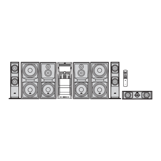
SERVICE MANUAL
COMPACT COMPONENT SYSTEM
2008
4 S ERVICE MANUAL
MB616<Rev.002>
DX-U10A, DX-U10US, DX-U10UX, DX-U10UG,
DX-U10UN, DX-U8US, DX-U8UX, DX-U8UG,
DX-U8UN, DX-U6US, DX-U6UX, DX-U6UG,
SP-DXU10W
SP-DXU10S
SP-DXU10F
SP-DXU10W
COPYRIGHT © 2008 Victor Company of Japan, Limited
Lead free solder used in the board (material : Sn-Ag-Cu, melting point : 219 Centigrade)
Lead free solder used in the board (material : Sn-Cu, melting point : 230 Centigrade)
1
PRECAUTION. . . . . . . . . . . . . . . . . . . . . . . . . . . . . . . . . . . . . . . . . . . . . . . . . . . . . . . . . . . . . . . . . . . . . . . . . 1-4
2
Specific Service Instructions . . . . . . . . . . . . . . . . . . . . . . . . . . . . . . . . . . . . . . . . . . . . . . . . . . . . . . 1-7
3
Disassembly . . . . . . . . . . . . . . . . . . . . . . . . . . . . . . . . . . . . . . . . . . . . . . . . . . . . . . . . . . . . . . . . . . . . . . . 1-8
4
Adjustment . . . . . . . . . . . . . . . . . . . . . . . . . . . . . . . . . . . . . . . . . . . . . . . . . . . . . . . . . . . . . . . . . . . . . . . 1-34
5
Troubleshooting . . . . . . . . . . . . . . . . . . . . . . . . . . . . . . . . . . . . . . . . . . . . . . . . . . . . . . . . . . . . . . . . . 1-35
DX-U6UN, DX-U10UH
CA-DXU10
SP-DXU10W
SP-DXU10F
SP-DXU10S
SUPER VIDEO
CA-DXU6
SP-DXU6F
SP-DXU6F
TABLE OF CONTENTS
COPYRIGHT © 2008 Victor Company of Japan, Limited
SP-DXU10C
SP-DXU10W
SP-DXU8S
SUPER VIDEO
CA-DXU8
SP-DXU8S
SP-DXU10F
SP-DXU10C
No.MB616<Rev.002>
2008/4
Advertisement
Table of Contents

Related Manuals for JVC DX-U10A


Summary of Contents for JVC DX-U10A
- Page 1 SERVICE MANUAL COMPACT COMPONENT SYSTEM MB616<Rev.002> 2008 4 S ERVICE MANUAL DX-U10A, DX-U10US, DX-U10UX, DX-U10UG, DX-U10UN, DX-U8US, DX-U8UX, DX-U8UG, DX-U8UN, DX-U6US, DX-U6UX, DX-U6UG, DX-U6UN, DX-U10UH SP-DXU10W CA-DXU10 SP-DXU10W SP-DXU10C SP-DXU10W CA-DXU8 SP-DXU8S SP-DXU10S SP-DXU10F SP-DXU10F SP-DXU10S SP-DXU8S SP-DXU10F SP-DXU10C SUPER VIDEO...
- Page 2 SPECIFICATION DX-U10/DX-U8 150 W per channel, min. RMS, driven into 4 Ω at 1 kHz with Amplifier section Output Power FRONT SPEAKERS no more than 10% total harmonic distortion. CA-DXU10 140 W per channel, min. RMS, driven into 6 Ω at 1 kHz with CENTER SPEAKER no more than 10% total harmonic distortion.
- Page 3 DX-U6 150 W per channel, min. RMS, driven into 4 Ω at 1 kHz with no more Amplifier section Output Power FRONT SPEAKERS than 10% total harmonic distortion. 150 W, min. RMS, driven into 4 Ω at 63 Hz with no more than 10% total SUBWOOFER harmonic distortion.
-
Page 4: Precaution
SECTION 1 PRECAUTION Safety Precautions (1) This design of this product contains special hardware and voltmeter. many circuits and components specially for safety purpos- Move the resistor connection to each exposed metal es. For continued protection, no changes should be made part, particularly any exposed metal part having a return to the original design unless authorized in writing by the path to the chassis, and measure the AC voltage across... - Page 5 Preventing static electricity Electrostatic discharge (ESD), which occurs when static electricity stored in the body, fabric, etc. is discharged, can destroy the laser diode in the traverse unit (optical pickup). Take care to prevent this when performing repairs. 1.5.1 Grounding to prevent damage by static electricity Static electricity in the work area can destroy the optical pickup (laser diode) in devices such as laser products.
- Page 6 Important for laser products 1.CLASS 1 LASER PRODUCT 5.CAUTION : If safety switches malfunction, the laser is able to function. 2.CAUTION : (For U.S.A.) Visible and/or invisible class II laser radiation 6.CAUTION : Use of controls, adjustments or performance of when open.
-
Page 7: Specific Service Instructions
SECTION 2 SPECIFIC SERVICE INSTRUCTIONS This service manual does not describe SPECIFIC SERVICE INSTRUCTIONS. (No.MB616<Rev.002>)1-7... -
Page 8: Disassembly
SECTION 3 DISASSEMBLY Main body (Using figures are DX-U10) 3.1.1 Removing the METAL COVER (See Fig.1, 2) (1) Remove the eight screws A attaching the METAL COVER. (See Fig.1) (2) Remove the six screws B attaching the both side of the METAL COVER. - Page 9 3.1.2 Removing the DVD CHANGER MECHANISM assembly (See Fig.3 to 6) (1) Remove the two screws C attaching the DVD MECHA- NISM assembly. (See Fig.3) (2) Disconnect the card wires from DVD MECHANISM assem- bly connected to connector CN800 CN810 of the MAIN BOARD assembly.
-
Page 10: Table Of Contents
3.1.3 Removing the VIDEO BOARD assembly (See Fig.7, 8) (1) Disconnect the card wire from MAIN BOARD assembly connected to connector CN920 of the VIDEO BOARD as- CN920 CN931 sembly. (See Fig.7) (2) Disconnect the card wire from SURROUND AMP BOARD assembly connected to connector CN931 of the VIDEO... -
Page 11: Table Of Contents
3.1.5 Removing the REAR COVER with FAN (See Fig.11, 12) (1) Remove the One screw G attaching the REAR COVER. (See Fig.11) (2) Disengage six hooks a engaged REAR COVER. (See Fig.11) (3) Disconnect the connector wire from FAN connected to con- nector CN304 of the SURROUND AMP BOARD assembly. -
Page 12: Table Of Contents
3.1.6 Removing the TUNER PACK (See Fig.13, 14) (1) Disconnect the card wire from TUNER PACK connected to connector CN750 of the MAIN BOARD assembly. (See Fig. 13) (2) Remove the two screws H attaching the TUNER PACK. (See Fig.14) CN750 Fig.13 Fig.14... - Page 13 3.1.7 Removing the REAR PANEL (See Fig.15, 16) (1) Remove the four screws J attaching the HEAT SINK by or- der. (See Fig.15) (2) Remove the five screws K attaching the REAR PANEL. (See Fig.15) (3) Disengage two hooks b engaged both side of the REAR PANEL.
-
Page 14: See Fig.
3.1.8 Removing the MAIN BOARD assembly (See Fig.17, 18) (1) Disconnect the card wire from FL BOARD assembly con- nected to connector CN720 of the MAIN BOARD assem- CN730 bly. (See Fig.17) CN720 (2) Disconnect the card wire from CASSETTE MECHANISM A connected to connector CN730 of the MAIN BOARD as-... - Page 15 3.1.9 Removing the REGULATOR BOARD assembly (See Fig.19, 20) (1) Disconnect the card wire from REGULATOR BOARD as- sembly connected to connector CN305 CN306 of the SURROUND AMP BOARD assembly. (See Fig.19) (2) Disconnect the card wire from FL BOARD assembly con- nected to connector CN207 of the REGULATOR BOARD...
- Page 16 3.1.10 Removing the SURROUND AMP BOARD assembly (See Fig.21) (1) Remove the two screws N attaching the POWER AMP IC. (2) Remove the one screw P attaching the IC BRACKET. 3.1.11 Removing the SUBWOOFER AMP BOARD assembly (See Fig.21) (1) Remove the four screws Q attaching the POWER AMP ICs.
- Page 17 3.1.13 Removing the CASSETTE MECHANISM B (SeeFig.24) (1) Disconnect the card wire from CASSETTE MECHANISM B connected to connector CN120 of the CASSETTE MECH- ANISM BOARD assembly of the CASSETTE MECHA- NISM A. (2) Disconnect the connector wire from CASSETTE MECHA- NISM B connected to connector CN200 of the CASSETTE...
- Page 18 3.1.15 Removing the FL BOARD assembly and SWITCH BOARD assembly (See Fig.26) (1) Remove the four screws V attaching the FL BOARD as- sembly. (2) Remove the six screws W attaching the SWITCH BOARD assembly. Fig.26 3.1.16 Removing the MIC BOARD assembly (See Fig.27) (1) Remove the two volume knobs.
- Page 19 DVD changer mechanism assembly section Remove the DVD changer mechanism assembly from the main body. (See "Removing the DVD changer mechanism assembly".) 3.2.1 Removing the tray assemblies (See Figs.1 to 5) (1) From the top side of the main body, remove the two screws Top cover A from the top cover and release the two joints a on the both sides of the DVD changer mechanism assembly.
- Page 20 Open det. lever Fig.3 Side(R) assembly Tray assemblies Fig.4 Tray assembly Fig.5 1-20 (No.MB616<Rev.002>)
- Page 21 3.2.2 Removing the DVD servo board (See Figs.6 to 8) Caution: Solder the short land sections d on the DVD pickup before dis- connecting the card wire extending from the DVD pickup. If you do not follow this instruction, the DVD pickup may be dam- DVD pickup aged.
-
Page 22: No.mb616
3.2.4 Removing the motor board (See Figs.9 and 10) (1) From the top side of the DVD changer mechanism assem- bly, remove the two belts from the motor pulleys. (See Fig.9.) Note: Take care not to attach grease on the belt. Belt Belt (2) Remove the two screws D attaching the motors to the load-...)1 - Page 23 3.2.6 Removing the DVD traverse mechanism assembly (See Fig.11) • Remove the tray assemblies and DVD servo board. DVD changer mechanism assembly (1) From the bottom side of the DVD changer mechanism as- sembly, remove the three screws F attaching the DVD traverse mechanism assembly.
- Page 24 3.2.7 Removing the DVD pickup (See Figs.12 to 14) • Remove the tray assemblies, DVD servo board and DVD DVD traverse mechanism assembly traverse mechanism assembly. Feed bracket (1) From the top side of the DVD traverse mechanism assem- Thrust spring bly, release the lock of the connector on the DVD pickup Connector and disconnect the card wire in the direction of the arrow.
- Page 25 DVD pickup Rack arm Guide shaft Rack arm spring Fig.14 Connector DVD pickup Screw shaft gear Fig.15 (No.MB616<Rev.002>)1-25...
- Page 26 3.2.9 Removing the spindle motor board (See Figs.16 and 17) • Remove the tray assemblies, DVD servo board and DVD DVD traverse mechanism assembly traverse mechanism assembly. (1) From the top side of the DVD traverse mechanism assem- Spindle motor board bly, remove the wires from the soldered sections r on the spindle motor board.
- Page 27 3.2.10 Removing the feed motor (See Figs.18 and 19) • Remove the tray assemblies and DVD traverse mechanism Feed bracket assembly. (1) From the top side of the DVD traverse mechanism assem- Thrust spring bly, remove the screw K attaching the feed bracket and re- move the feed bracket from the sections t.
- Page 28 3.2.11 Removing the side (L) and tray switch board (See Figs.20 to 22) • Remove the tray assemblies. SIde(L) (1) From the topside of the DVD changer mechanism assem- bly, remove the two screws M attaching the side (L). (See Fig.20.) (2) From the left side of the DVD changer mechanism assem- bly, disconnect the connector...
- Page 29 3.2.12 Removing the side (R) assembly (See Fig.23 to 27) • Remove the tray assemblies and DVD servo board. Elevator spring (1) From the inside of the side (R) assembly, release the two tabs aa of the gear cover and remove the gear cover out- ward.
- Page 30 3.2.13 Removing the lifter assembly (See Figs.28 to 32) • Remove the tray assemblies, DVD servo board, side (L) and Hook side (R) assembly. (1) From the top side of the DVD changer mechanism assem- bly, turn the gear 1 clockwise to move the lifter assembly upward.
- Page 31 3.2.14 Removing the sensor board and SV resistor (See Fig.33) • Remove the tray assemblies, side (L), side (R) assembly and Sensor board lifter assembly. (1) Remove the solders from the soldered sections aj on the sensor board and remove the wires. (2) Remove the two screws Q and take out the sensor board with the SV resistor.
- Page 32 3.2.15 Taking out the disc in the play mode (See Fig.34 to 37) Reference: Tray assembly Refer to "Removing the tray assemblies". (1) From the top side of the DVD changer mechanism assem- bly, remove the top cover. (2) Unlock the tray assemblies and draw out the tray assem- blies toward the front.
- Page 33 Tray stopper Main tray Sub tray Fig.36 Tray stopper Fig.37 (No.MB616<Rev.002>)1-33...
-
Page 34: Adjustment
SECTION 4 ADJUSTMENT Attention in service of DVD section (1) When pickup, Flash ROM, DVD module board were changed, initialize EEPROM by all means. (2) When full initialization was executed, execute learning with a DVD test disk by all means. Test disc : VT-501, VT-502 Learning method : It is adjusted automatically by normal playback of a DVD test disc. -
Page 35: Troubleshooting
viii) During CHECK mode, press '8' key on REMOTE CONTROL to view DVD module EEPROM content in +1 address step. (2 seconds) (Static) ix) During CHECK mode, press '9' key on REMOTE CONTROL to perform TEMPERATURE SENSOR VALUE. (2 seconds) (Static) x) During CHECK mode, press '10' key on REMOTE CONTROL to perform SEARCH DVD_DL PARALLEL DISC DESIGNATED POSITION and JITTER MEASUREMENT... - Page 36 Victor company of Japan, Limited Audio/Video Systems category 10-1,1chome,Ohwatari-machi,Maebashi-city,371-8543,Japan (No.MB616<Rev.002>) Printed in Japan...
- Page 37 SCHEMATIC DIAGRAMS COMPACT COMPONENT SYSTEM DX-U10A,DX-U10US,DX-U10UX DX-U10UG,DX-U10UN,DX-U8US DX-U8UX,DX-U8UG,DX-U8UN DX-U6US,DX-U6UX,DX-U6UG DX-U6UN CD-ROM No.SML200706 SP-DXU10W CA-DXU10 SP-DXU10W SP-DXU10C SP-DXU10W CA-DXU8 SP-DXU8S SP-DXU10S SP-DXU10F SP-DXU10F SP-DXU10S SP-DXU8S SP-DXU10F SP-DXU10C SUPER VIDEO SUPER VIDEO SP-DXU10W CA-DXU6 SP-DXU6F SP-DXU6F Lead free solder used in the board (material : Sn-Ag-Cu, melting point : 219 Centigrade)
- Page 38 In regard with component parts appearing on the silk-screen printed side (parts side) of the PWB diagrams, the parts that are printed over with black such as the resistor ( ), diode ( ) and ICP ( ) or identified by the " " mark nearby are critical for safety.
-
Page 39: Block Diagram
Block diagram DVD tray control section Video & Digital output section TRAY/POSITION IC1, IC2 MOTPSW USB6V OPTICAL MOTOR TRAY/POSITION MOTOR DRIVER TRAY OPEN SW USB6V DIGITAL OUT MTOP, MTCL NOTES: (CN303) Used for DX-U6 POSITION SUB TRAY SW1 to SW5 CLSWT1 to 5 POSMUP S/COMPOSITE... - Page 40 Standard schematic diagrams Primary section CN203 QGB2510K2-16 F2006 D2202 D2200 C1001 F1001 1N5402M-20 1N5402M-20 D2203 D2201 S1000 1N5402M-20 1N5402M-20 QSW0812-001 B1951 F1002 B1201 PP201 D2204 F2005 QNZ0104-001 2A02-M F2004 CN101 W201 QGA7901C1-04 QUB070-22BXDM-E F2003 S3DC CN201 F2001 QGA3901C1-10 F2002 D2101 D2001 GBU803 GBU803...
- Page 41 DC regulator/Audio output section (for DX-U10) FW301 QUM156-27DGZ4-E IC301 STK416-130-E IC306 IC305 KIA278R09PI PQ050RDC2SZF IC302 IC304 IC303 KIA7812API KIA7809API KIA78D06PI-U/P R3305 D3812 R3307 R3306 D3306 D3822 1N5402M-20 B3110 B3111 B3112 D3813 D3823 D3305 1N5402M-20 C3402 D3814 D3302 D3301 D3824 R3602 MTZJ15B-T2 3.3P MTZJ15B-T2...
- Page 42 DC regulator/Audio output section (for DX-U8) FW301 QUM156-27DGZ4-E IC307 STK433-240-E IC306 IC305 KIA278R09PI PQ050RDC2SZF IC302 IC304 IC303 KIA7812API KIA7809API KIA78D06PI-U/P R3305 D3812 R3307 R3306 D3306 D3822 B3110 B3111 B3112 D3813 D3823 D3305 D3845 D3814 C3402 D3302 D3301 D3824 3.3P R3602 C3221 C3211 220P...
- Page 43 DC regulator/Audio output section (for DX-U6) FW301 QUM156-27DGZ4-E IC301 IC306 IC305 KIA278R09PI PQ050RDC2SZF IC303 IC302 IC304 KIA7812API KIA78D06PI-U/P KIA7809API R3305 D3812 R3307 R3306 D3306 D3822 B3110 B3111 B3112 D3813 D3823 D3305 D3845 C3402 D3814 D3302 D3301 D3824 R3602 C3221 C3211 R3402 C3201 C3602...
- Page 44 System control/External input/Source selector section UN2113-X UN2111-X UN2213-X UN2215-X UN2214-X QGF1205C2-11 CN760 QGF1205F2-13 CN720 C7700 10/50 CN800 QGF1036C2-10 R8172 R8174 B7700 C8100 C8176 R8100 0.1/50 C8101 K8000 R8206 R8205 R8102 R8103 R8104 C8074 10/63 NQR0627-004X 1/50 10/63 C8172 10/50 1/50 Q8071 10/50 C8174...
- Page 45 Video output/Mic circuit/FL display/User control key section C5000 22/50 FL500 QLF0188-001 C5001 22/50 IC510 CN901 C5010 GP1UM281XKVF QGF1205C2-15 R9015 R9013 C5011 C5002 C9035 R5047 FL-CLK 100P 0.001 JS901 JS902 R9035 FL-DATA 1/50 R9011 C9008 FL-LATCH R5051 IC500 PT6324-HT IC901 R5050 NJM4565E-X R5049 J901...
- Page 46 Cassette mechanism control section GVA10149 TAPE B : TAPE A : QAL0968-001 QAL0967-001 (R/P 2WAY) (PB 2WAY) R220 R221 R211 Q205 RECL R210 0.86V 2.4K C217 Q200 RT1P430C-X 0.84V C219 0.01/50 C218 Q201 0.84V RT6N430C 4.7K 4.7K Q202 0.84V CN110 RT6N430C C220 R209...
- Page 47 DVD section (1/3) (for DX-U10, DX-U8) K354 48MHz NQR0022-002X C370 D1.2V REG. C328 0.01 DVDPWR 3.9V Cont D1.2V 1.2V P3.3V C302 47/4 IC302 MM1701CH-X CN301 for ICE D301 DGND CPURST RESET EEPROM R306 SCLK C564 DGND R307 SDATA DGND UCLK EXDT8 R353 (UCLK)
- Page 48 DVD section (2/3) (for DX-U10, DX-U8) SDRAM FLASH ROM IC505 IC509 SG32A90TFIR3 K4S641632K-UC75 EXADT15 0.4V 0.5V EXADR16 C560 3.3V EXADT14 0.7V 3.3V 2.8V 2.7V MDQ15 MDQ0 */BYTE DQ15 EXADT13 0.5V C551 3.3V VDDQ VSSQ EXADT12 0.7V 0.8V EXDT15 MDQ1 2.8V 2.7V MDQ14 DQ14...
- Page 49 DVD section (3/3) (for DX-U10, DX-U8) P3.3V DGND R859 R860 Q801 UN2113X IC801 MM1565AF-X KRA104S-X R891 Vout CN801 QGF1016F8-05W IC891 Cont C819 CN811 QGA2001F6-05X R819 R811 1/2W K811 R812 K812 1/2W LVA10543-601D (3/3) NOTES VOLTAGES ARE DC-MEASURED WITH A DIGITAL VOLT METER WITHOUT INPUT SIGNAL.
- Page 50 DVD section (1/3) (for DX-U6) K354 48MHz NQR0022-002X C370 D1.2V REG. C328 0.01 DVDPWR 3.9V Cont D1.2V 1.2V P3.3V C302 47/4 IC302 MM1701CH-X CN301 for ICE D301 DGND CPURST RESET EEPROM R306 SCLK C564 DGND R307 SDATA DGND UCLK EXDT8 R353 (UCLK) S2CLK...
- Page 51 DVD section (2/3) (for DX-U6) SDRAM FLASH ROM IC505 IC509 SG32A90TFIR3 K4S641632K-UC75 EXADT15 0.4V 0.5V EXADR16 C560 3.3V EXADT14 0.7V 3.3V 2.8V 2.7V MDQ15 MDQ0 */BYTE DQ15 EXADT13 0.5V C551 3.3V VDDQ VSSQ EXADT12 0.7V 0.8V EXDT15 MDQ1 2.8V 2.7V MDQ14 DQ14 EXADT11...
- Page 52 DVD section (3/3) (for DX-U6) P3.3V DGND R859 R860 Q801 UN2113X IC801 MM1565AF-X KRA104S-X R891 Vout CN801 QGF1016F8-05W IC891 Cont C819 CN811 QGA2001F6-05X R819 R811 1/2W K811 R812 K812 1/2W LVA10543-611D (3/3) NOTES VOLTAGES ARE DC-MEASURED WITH A DIGITAL VOLT METER WITHOUT INPUT SIGNAL.
- Page 53 Loader section QVY0027-B14 WJM0331-001A-E QSW0923-001 WJM0330-002A-E LB1641 LB1641 TR3_CL TR2_CL QSW0854-002 TR4_CL TR1_CL TR5_CL M.TR_OP M.TR_OP TR5_CL TR5_CL TR4_CL TR4_CL POS_UP TR3_CL TR3_CL TR_OP TR2_CL TR2_CL POS_DOWN TR1_CL TR1_CL TR_CL 0.1/50 0.1/50 QSW0886-002 QRA0164-001 QRA0164-001 2-15...
- Page 54 Printed circuit boards Main board Lead free solder used in the board (material : Sn-Ag-Cu, melting point : 219 Centigrade) Lead free solder used in the board (material : Sn-Cu, melting point : 230 Centigrade) K9102 (Video board) K9101 R7084 R7085 FW910 R7898...
- Page 55 Amplifier board Lead free solder used in the board (material : Sn-Ag-Cu, melting point : 219 Centigrade) Lead free solder used in the board (material : Sn-Cu, melting point : 230 Centigrade) (Amplifier 2 board) CN403 R4007 (Bridge board) R4811 C4404 R2307 PP205...
- Page 56 Display board DVD board Lead free solder used in the board (material : Sn-Ag-Cu, melting point : 219 Centigrade) Lead free solder used in the board (material : Sn-Ag-Cu, melting point : 219 Centigrade) Lead free solder used in the board (material : Sn-Cu, melting point : 230 Centigrade) Lead free solder used in the board (material : Sn-Cu, melting point : 230 Centigrade) (Switch board) forward side...
- Page 57 Loader board Lead free solder used in the board (material : Sn-Ag-Cu, melting point : 219 Centigrade) Lead free solder used in the board (material : Sn-Cu, melting point : 230 Centigrade) (Motor board) (Tray switch board) (Sensor board) (Switch board) Cassette board Lead free solder used in the board (material : Sn-Ag-Cu, melting point : 219 Centigrade) Lead free solder used in the board (material : Sn-Cu, melting point : 230 Centigrade)
- Page 58 Victor Company of Japan, Limited Audio/Video Systems Category 10-1,1chome,Ohwatari-machi,Maebashi-city,371-8543,Japan Printed in Japan (No.MB616SCH)
-
Page 59: Parts List
PARTS LIST DX-U10A,DX-U10US,DX-U10UX DX-U10UG,DX-U10UN,DX-U8US DX-U8UX,DX-U8UG,DX-U8UN DX-U6US,DX-U6UX,DX-U6UG DX-U6UN,DX-U10UH * All printed circuit boards and its assemblies are not available as service parts. - Contents - 3- 2 Exploded view of general assembly and parts list (Block No.M1)(DX-U10) 3- 6 Exploded view of general assembly and parts list (Block No.M2) (DX-U8) 3-10 Exploded view of general assembly and parts list (Block No.M3) (DX-U6) - Page 60 Exploded view of general assembly and parts list Block No. <DX-U10> FL board Cassete A 16 2 Cassette B Microphone amplifier board...
- Page 61 80 79 Except A Video board Amplifier 1 board Primary board Amplifier 2 board Bridge board Cassete A Main board board...
- Page 62 General Assembly (DX-U10) Block No. [M][1][M][M] Symbol No. Part No. Part Name Description Local GV10377-001A FRONT PANEL ASSY GV40753-001A JVC BADGE GV20464-003A FL LENS GV20465-001A BUTTON LENS GV31000-001A TRAY FITTING 1 GV31001-001A TRAY FITTING 2 GV31002-001A TRAY FITTING 3...
- Page 63 Symbol No. Part No. Part Name Description Local GV30349-026A SPACER GV10263-002A REAR COVER QYSBSGY3008EA TAP SCREW M3 x 8mm QAU0492-001 TUNER QYSBSGY3008EA TAP SCREW M3 x 8mm(x2) QYSBSGY3008EA TAP SCREW M3 x 8mm(x4) QYSBSGY3008EA TAP SCREW M3 x 8mm QYSBSGY3008EA TAP SCREW M3 x 8mm...
- Page 64 Exploded view of general assembly and parts list Block No. <DX-U8> FL board Cassete A 16 2 Cassette B Microphone amplifier board...
- Page 65 80 79 Video board Amplifier 1 board Primary board Amplifier 2 board Bridge board Cassete A Main board board...
- Page 66 General Assembly (DX-U8) Block No. [M][2][M][M] Symbol No. Part No. Part Name Description Local GV10377-001A FRONT PANEL ASSY GV40753-001A JVC BADGE GV20464-002A FL LENS GV20465-001A BUTTON LENS GV31000-001A TRAY FITTING 1 GV31001-001A TRAY FITTING 2 GV31002-001A TRAY FITTING 3...
- Page 67 Symbol No. Part No. Part Name Description Local QAU0492-001 TUNER QYSBSGY3008EA TAP SCREW M3 x 8mm(x2) QYSBSGY3008EA TAP SCREW M3 x 8mm(x4) QYSBSGY3008EA TAP SCREW M3 x 8mm QYSBSGY3008EA TAP SCREW M3 x 8mm QYSBSGY3008EA TAP SCREW M3 x 8mm QYSBSGY3008EA TAP SCREW M3 x 8mm...
- Page 68 Exploded view of general assembly and parts list Block No. <DX-U6> FL board Cassete A 16 2 Cassette B Microphone amplifier board 3-10...
- Page 69 80 79 Video board Amplifier 1 board Primary board Amplifier 2 board Bridge board Cassete A Main board board 3-11...
- Page 70 General Assembly (DX-U6) Block No. [M][3][M][M] Symbol No. Part No. Part Name Description Local GV10377-001A FRONT PANEL ASSY GV40753-001A JVC BADGE GV20464-001A FL LENS GV20465-001A BUTTON LENS GV31000-001A TRAY FITTING 1 GV31001-001A TRAY FITTING 2 GV31002-001A TRAY FITTING 3...
- Page 71 Symbol No. Part No. Part Name Description Local QAU0492-001 TUNER QYSBSGY3008EA TAP SCREW M3 x 8mm(x2) QYSBSGY3008EA TAP SCREW M3 x 8mm(x4) QYSBSGY3008EA TAP SCREW M3 x 8mm QYSBSGY3008EA TAP SCREW M3 x 8mm QYSBSGY3008EA TAP SCREW M3 x 8mm QYSBSGY3008EA TAP SCREW M3 x 8mm...
- Page 72 DVD mechanism assembly and parts list Block No. Grease FXL-D20-11M =JVG-31N =JVS-1003 =1401C < Back side > 7.0mm 0.2mm The parts without symbol number are not service. 3-14...
- Page 73 DVD mechanism Block No. [M][J][M][M] Symbol No. Part No. Part Name Description Local LV22234-001A TM.CHASSIS LV22294-001A C.SPINDLE BASE QYSDST2005ZA TAP SCREW M2 x 5mm(x2) LV36791-001A C.G.S.HOLDER QYSDST2005ZA TAP SCREW M2 x 5mm LV44041-002A GUIDE SHAFT LV44479-001A BAR SPRING LV22236-001A FEED HOLDER QAR0165-001 FEED MOTOR...
- Page 74 DVD changer mechanism assembly and parts list (Except DX-U6) Block No. FMU-SB6-1M Grease =JVG-31N =JVS-1003 CH5-BASE-1M The parts without symbol number are not service. 3-16...
- Page 75 DVD changer mechanism (Except DX-U6) Block No. [M][K][M][M] Symbol No. Part No. Part Name Description Local LV10913-001A LOADER ASSY QVY0027-B14 S V RESISTOR QYSDST2004Z SCREW 2mm x 4mm QAR0164-001 MOTOR (x2) LV42340-001A MOTOR PULLEY (x2) LV41431-002A BELT (x2) QYSPSPU1725N SCREW 1.7mm x 2.5mm(x2) LV33965-004A...
- Page 76 DVD changer mechanism assembly and parts list (Only DX-U6) Block No. FMU-SB6-11M Grease =JVG-31N =JVS-1003 CH5-BASE-1M The parts without symbol number are not service. 3-18...
- Page 77 DVD changer mechanism (Only DX-U6) Block No. [M][T][M][M] Symbol No. Part No. Part Name Description Local LV10913-004A LOADER ASSY QVY0027-B14 S V RESISTOR QYSDST2004ZA TAP SCREW M2 x 4mm QAR0164-001 MOTOR (x2) LV42340-001A MOTOR PULLEY (x2) LV41431-002A BELT (x2) QYSPSPU1725NA SCREW M1.7 x 2.5mm(x2)
-
Page 78: Electrical Parts List
Electrical parts list Main board Symbol No. Part No. Part Name Description Local Block No. [0][1] Q8212 RT1N441C-X TRANSISTOR 10A,10US,10UX, Symbol No. 10UG,10UN,8US, Part No. Part Name Description Local 8UX,8UG,8UN,1 Q8403 RT1N240C-X TRANSISTOR 6US,6UX,6UG, IC770 ------------ MICON IC IC771 BR24L08F-W-X IC(DIGITAL) - Page 79 Symbol No. Symbol No. Part No. Part Name Description Local Part No. Part Name Description Local C8001 QTE1J46-106Z E CAPACITOR 10uF 63V C8076 QETN1HM-104Z E CAPACITOR 0.1uF 50V M 10A,10US,10UX, 10UG,10UN,8US, C8003 NDC31HJ-271X C CAPACITOR 270pF 50V J 10A,10US,10UX, 8UX,8UG,8UN, 10UG,10UN,...
- Page 80 Symbol No. Symbol No. Part No. Part Name Description Local Part No. Part Name Description Local C8132 QTE1H53-226Z E CAPACITOR 22uF 50V 8US,8UX,8UG, C8512 NCB31HK-103X C CAPACITOR 0.01uF 50V K 8UN,6US,6UX, C8513 NCB31CK-104X C CAPACITOR 0.1uF 16V K 6UG,6UN C8514 NDC31HJ-101X...
- Page 81 Symbol No. Symbol No. Part No. Part Name Description Local Part No. Part Name Description Local R7050 NRSA63J-753X MG RESISTOR 75kΩ 1/16W J 10A,10US,10UX, R7805 NRSA63J-103X MG RESISTOR 10kΩ 1/16W J 10UG,10UN, R7808 NRSA63J-103X MG RESISTOR 10kΩ 1/16W J 10UH R7809 NRSA63J-103X...
- Page 82 Symbol No. Symbol No. Part No. Part Name Description Local Part No. Part Name Description Local R8036 NRSA63J-0R0X MG RESISTOR 0Ω 1/16W J 8US,8UX,8UG, R8091 NRSA63J-105X MG RESISTOR 1MΩ 1/16W J 10A,10US,10UX, 8UN,6US,6UX, 10UG,10UN,8US, 6UG,6UN 8UX,8UG,8UN, 10UH R8037 NRSA63J-103X MG RESISTOR 10kΩ...
- Page 83 Symbol No. Symbol No. Part No. Part Name Description Local Part No. Part Name Description Local R8146 NRSA63J-103X MG RESISTOR 10kΩ 1/16W J 8US,8UX,8UG, R8191 NRSA63J-105X MG RESISTOR 1MΩ 1/16W J 10A,10US,10UX, 8UN,6US,6UX, 10UG,10UN,8US, 6UG,6UN 8UX,8UG,8UN, 10UH R8160 NRSA63J-302X MG RESISTOR 3kΩ...
- Page 84 Symbol No. Symbol No. Part No. Part Name Description Local Part No. Part Name Description Local R8292 NRSA63J-823X MG RESISTOR 82kΩ 1/16W J 6US,6UX,6UG, CN740 QGF1208F1-15 CONNECTOR FFC/FPC (1- 10UH R8414 NRSA63J-681X MG RESISTOR 680Ω 1/16W J 6US,6UX,6UG, CN750 QGF1205F2-11 CONNECTOR...
- Page 85 Symbol No. Symbol No. Part No. Part Name Description Local Part No. Part Name Description Local J921 QNN0557-002 PIN JACK D2312 MTZJ7.5B-T2 Z DIODE JS901 QSW1230-001 MIC ENCODER D2314 MTZJ36A-T2 Z DIODE JS902 QSW1230-001 MIC ENCODER D2315 1N4003S-T5 SI DIODE K7000 NQR0627-004X...
- Page 86 Symbol No. Symbol No. Part No. Part Name Description Local Part No. Part Name Description Local C3604 QFLC1HJ-104Z M CAPACITOR 0.1uF 50V J R3402 QRE141J-563Y C RESISTOR 56kΩ 1/4W J R3403 C3605 QFLC1HJ-104Z M CAPACITOR 0.1uF 50V J QRJ146J-100X UNF C RESISTOR 10Ω...
- Page 87 Symbol No. AMP board(DX-U8) Part No. Part Name Description Local Block No. [0][3] R4606 QRE141J-561Y C RESISTOR 560Ω 1/4W J Symbol No. R4607 QRE141J-473Y C RESISTOR 47kΩ 1/4W J Part No. Part Name Description Local R4608 QRE141J-562Y C RESISTOR 5.6kΩ...
- Page 88 Symbol No. Symbol No. Part No. Part Name Description Local Part No. Part Name Description Local C3104 QETN1HM-105Z E CAPACITOR 1uF 50V M R3201 QRE141J-102Y C RESISTOR 1kΩ 1/4W J C3201 QCBB1HK-221Y C CAPACITOR 220pF 50V K R3202 QRE141J-102Y C RESISTOR 1kΩ...
- Page 89 Symbol No. Symbol No. Part No. Part Name Description Local Part No. Part Name Description Local R4812 QRE141J-563Y C RESISTOR 56kΩ 1/4W J Q4902 KTA1268/GL/-T TRANSISTOR R4901 QRE141J-103Y C RESISTOR 10kΩ 1/4W J Q4903 KTC3199/GL/-T TRANSISTOR R4902 QRE141J-104Y C RESISTOR 100kΩ...
- Page 90 Symbol No. Symbol No. Part No. Part Name Description Local Part No. Part Name Description Local C4801 QCBB1HK-101Y C CAPACITOR 100pF 50V K R4956 QRE141J-202Y C RESISTOR 2kΩ 1/4W J C4802 QTE1J46-106Z E CAPACITOR 10uF 63V R4957 QRE141J-473Y C RESISTOR 47kΩ...
- Page 91 Symbol No. Symbol No. Part No. Part Name Description Local Part No. Part Name Description Local D5502 SELT2E10C-S 10UH CN500 QGF1205F2-13 CONNECTOR FFC/FPC (1-13) 10A,10US, 10UX,10UG, D5503 SELU2E10C-P 10A,10US, 10UN,8US, 10UX,10UG, 8UX,8UG, 10UN,8US, 8UN,6US, 8UX,8UG, 6UX,6UG, 8UN,6US, 6UX,6UG, CN500 QGF1208F1-13 CONNECTOR...
- Page 92 Symbol No. Symbol No. Part No. Part Name Description Local Part No. Part Name Description Local Q201 RT6N430C-X TRANSISTOR R228 NRSA63J-822X MG RESISTOR 8.2kΩ 1/16W J Q202 RT6N430C-X TRANSISTOR R300 NRSA63J-153X MG RESISTOR 15kΩ 1/16W J Q203 RT6N430C-X TRANSISTOR R301 NRSA63J-153X...
- Page 93 Symbol No. Symbol No. Part No. Part Name Description Local Part No. Part Name Description Local C256 NCB31CK-104X C CAPACITOR 0.1uF 16V K C559 NCB31CK-104X C CAPACITOR 0.1uF 16V K C257 NCB31HK-822X C CAPACITOR 8200pF 50V K C560 NCB31CK-104X C CAPACITOR 0.1uF 16V K...
- Page 94 Symbol No. Symbol No. Part No. Part Name Description Local Part No. Part Name Description Local R334 NRSA63J-0R0X MG RESISTOR 0Ω 1/16W J CN701 QGF1016F8-28W CONNECTOR FFC/FPC (1-28) R335 NRSA63J-0R0X MG RESISTOR 0Ω 1/16W J CN702 QGF1016F8-10W CONNECTOR FFC/FPC (1-10) R336 NRSA63J-0R0X...
- Page 95 DVD servo board(Only DX-U6) Symbol No. Part No. Part Name Description Local Block No. [0][9] C328 NCB31HK-103X C CAPACITOR 0.01uF 50V K Symbol No. Part No. Part Name Description Local C330 NCB31CK-104X C CAPACITOR 0.1uF 16V K C331 NCB31CK-333X C CAPACITOR 0.033uF 16V K...
- Page 96 Symbol No. Symbol No. Part No. Part Name Description Local Part No. Part Name Description Local R115 NRSA63J-102X MG RESISTOR 1kΩ 1/16W J R541 NRSA63J-472X MG RESISTOR 4.7kΩ 1/16W J R116 NRSA63J-471X MG RESISTOR 470Ω 1/16W J R701 NRSA63J-2R2X MG RESISTOR 2.2Ω...
- Page 97 DVD loading board(Only DX-U6) Block No. [1][0] Symbol No. Part No. Part Name Description Local LB1641 LB1641 MTZJ6.2A-T2 Z DIODE QEKC1AM-107Z E CAPACITOR 100uF 10V M QCBB1HK-104Y C CAPACITOR 0.1uF 50V K QFLC1HJ-103Z M CAPACITOR 0.01uF 50V J QFLC1HJ-103Z M CAPACITOR 0.01uF 50V J QCBB1HK-104Y...
- Page 98 Packing materials and accessories parts list <DX-U10> Block No. No additional / supplemental order of WARRANTY CARDs are available A1, A2, A3, A4, A3, A4, A7, A9, US,UN UX,UG,UH Only A The parts without symbol number are not service. 3-40...
- Page 99 Packing and Accessories (DX-U10) Block No. [M][4][M][M] Symbol No. Part No. Part Name Description Local QAL0014-003 AM LOOP ANT QAL0476-003 AM LOOP ANT 10UH QAM0112-002 CONVERSION PLUG 10US,10UN QAM0944-001 PIN CABLE RM-SDXU10U REMOCON QAL0457-001 ANT.WIRE ------------ BATTERY 1.5V(x2) GVT0210-001A INST BOOK GVT0210-005A...
- Page 100 Packing materials and accessories parts list Block No. <DX-U8> A1, A2, A3, A4, A8(Only UG) US,UN UX,UG The parts without symbol number are not service. 3-42...
- Page 101 Packing and Accessories (DX-U8) Block No. [M][5][M][M] Symbol No. Part No. Part Name Description Local QAL0014-003 AM LOOP ANT QAM0112-002 CONVERSION PLUG 8US,8UN QAM0944-001 PIN CABLE RM-SDXU10U REMOCON QAL0457-001 ANT.WIRE ------------ BATTERY 1.5V(x2) GVT0210-001A INST BOOK GVT0210-005A INST BOOK CHI(PEKIN) 8US,8UN GVT0210-006A...
- Page 102 Packing materials and accessories parts list Block No. <DX-U6> A1, A2, A3, A4, US,UN UX,UG The parts without symbol number are not service. 3-44...
- Page 103 Packing and Accessories (DX-U6) Block No. [M][6][M][M] Symbol No. Part No. Part Name Description Local QAL0014-003 AM LOOP ANT QAM0112-002 CONVERSION PLUG 6US,6UN QAM0944-001 PIN CABLE RM-SDXU6U REMOCON QAL0457-001 ANT.WIRE ------------ BATTERY 1.5V(x2) GVT0209-001A INST BOOK GVT0209-003A INST BOOK CHI(PEKIN) 6US,6UN GVT0209-004A...