Table of Contents
Advertisement
SERVICE MANUAL
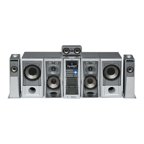
COMPACT COMPONENT SYSTEM
5
2005
MB368
DX-T9,DX-T7,DX-T5
(CA-DXT7,CA-DXT9)
DX-T9
DX-T7
DX-T5
Lead free solder used in the board (material : Sn-Ag-Cu, melting point : 219 Centigrade)
1
Precaution. . . . . . . . . . . . . . . . . . . . . . . . . . . . . . . . . . . . . . . . . . . . . . . . . . . . . . . . . . . . . . . . . . . . . . . . . 1-6
2
Specific Service Instructions . . . . . . . . . . . . . . . . . . . . . . . . . . . . . . . . . . . . . . . . . . . . . . . . . . . . . . 1-9
3
Disassembly . . . . . . . . . . . . . . . . . . . . . . . . . . . . . . . . . . . . . . . . . . . . . . . . . . . . . . . . . . . . . . . . . . . . . . 1-10
4
Adjustment . . . . . . . . . . . . . . . . . . . . . . . . . . . . . . . . . . . . . . . . . . . . . . . . . . . . . . . . . . . . . . . . . . . . . . . 1-51
5
Troubleshooting . . . . . . . . . . . . . . . . . . . . . . . . . . . . . . . . . . . . . . . . . . . . . . . . . . . . . . . . . . . . . . . . . 1-61
(SP-XST5)
(SP-XT5)
(CA-DXT5)
Main body
Front speaker
Subwoofer
CA-DXT9
SP-XT9
SP-WT9
CA-DXT7
SP-XT7
SP-WT7
CA-DXT5
SP-XT5
TABLE OF CONTENTS
COPYRIGHT © 2005 Victor Company of Japan, Limited
(SP-XT5)
(SP-XST5)
Surround speaker
Center speaker
SP-XST9
SP-XCT9
SP-XST7
SP-XCT7
---
SP-XST5
SP-XCT5
DX-T9, DX-T7
Area suffix
A
------------------------
Australia
US ------------------------ Singapore
UW ----------- Brazil,Mexico,Peru
UX -------------------- Saudi Arabia
UG --- Turkey,South Africa,Egypt
UN ----------------------------- Asean
DX-T5
Area suffix
US ------------------------ Singapore
UW ----------- Brazil,Mexico,Peru
UX -------------------- Saudi Arabia
UY ------------------------ Argentina
UG --- Turkey,South Africa,Egypt
UN ----------------------------- Asean
No.MB368
2005/5
Advertisement
Table of Contents

Related Manuals for JVC DX-T7


Summary of Contents for JVC DX-T7
- Page 1 SERVICE MANUAL COMPACT COMPONENT SYSTEM MB368 2005 DX-T9,DX-T7,DX-T5 DX-T9, DX-T7 Area suffix ------------------------ Australia US ------------------------ Singapore UW ----------- Brazil,Mexico,Peru UX -------------------- Saudi Arabia UG --- Turkey,South Africa,Egypt UN ----------------------------- Asean DX-T5 Area suffix US ------------------------ Singapore UW ----------- Brazil,Mexico,Peru...
- Page 2 SPECIFICATION CA-DXT9 150 W per channel, min. RMS, driven into 4 Ω at 1 kHz Amplifier section Output Power FRONT SPEAKERS with no more than 10% total harmonic distortion. 140 W per channel, min. RMS, driven into 6 Ω at 1 kHz CENTER SPEAKER with no more than 10% total harmonic distortion.
- Page 3 CA-DXT7 150 W per channel, min. RMS, driven into 4 Ω at 1 kHz Amplifier section Output Power FRONT SPEAKERS with no more than 10% total harmonic distortion. 50 W per channel, min. RMS, driven into 6 Ω at 1 kHz CENTER SPEAKER with no more than 10% total harmonic distortion.
- Page 4 DX-T5 150 W per channel, min. RMS, driven into 4 Ω at 1 kHz Amplifier section Output Power MAIN SPEAKERS with no more than 10% total harmonic distortion. Digital output OPTICAL DIGITAL OUTPUT -21 dBm to -15 dBm (660 nm ±30 nm) Audio input sensitivity/ 300 mV/47 kΩ...
- Page 5 Speakers Main Speakers Type 3-Way 3-Speaker Bass Reflex (Magnetically-Shielded Type) 18 cm cone × 1 Speaker systems Woofer 5 cm cone × 1 2 cm dome × 1 Tweeter Power handling capacity 150 W 4 Ω Impedance Frequency range 37 Hz - 31 000 Hz Sound pressure level 85 dB/W·m Dimensions (W/H/D) (approx.) 204 mm ×...
- Page 6 SECTION 1 PRECAUTION Safety Precautions (1) This design of this product contains special hardware and voltmeter. many circuits and components specially for safety purpos- Move the resistor connection to each exposed metal es. For continued protection, no changes should be made part, particularly any exposed metal part having a return to the original design unless authorized in writing by the path to the chassis, and measure the AC voltage across...
- Page 7 Preventing static electricity Electrostatic discharge (ESD), which occurs when static electricity stored in the body, fabric, etc. is discharged, can destroy the laser diode in the traverse unit (optical pickup). Take care to prevent this when performing repairs. 1.5.1 Grounding to prevent damage by static electricity Static electricity in the work area can destroy the optical pickup (laser diode) in devices such as laser products.
- Page 8 Important for laser products 5.CAUTION : If safety switches malfunction, the laser is able 1.CLASS 1 LASER PRODUCT to function. 2.DANGER : Invisible laser radiation when open and inter 6.CAUTION : Use of controls, adjustments or performance of lock failed or defeated. Avoid direct exposure to beam. procedures other than those specified here in may result in 3.CAUTION : There are no serviceable parts inside the hazardous radiation exposure.
- Page 9 SECTION 2 SPECIFIC SERVICE INSTRUCTIONS This service manual does not describe SPECIFIC SERVICE INSTRUCTIONS. (No.MB368)1-9...
- Page 10 SECTION 3 DISASSEMBLY Main body section 3.1.1 Removing the metal cover (See Figs.1 to 3) (1) From the both sides of the main body, remove the six Metal cover screws A attaching the metal cover. (See Figs.1 and 2.) (2) From the back side of the main body, remove the eight screws B attaching the metal cover.
- Page 11 3.1.2 Removing the front panel assembly (See Figs.4 to 6) • Remove the metal cover. Main board Front panel assembly (1) From the right side of the main body, disconnect the card wire from the connectors CN740 on the reverse side of the CN730 CN720 main board.
- Page 12 3.1.3 Removing the tuner (See Fig.7) • Remove the metal cover. Rear panel Tuner (1) From the back side of the main body, remove the two screws E attaching the tuner to the rear panel. (2) Take out the tuner from the main body and disconnect the card wire from the connector on the tuner.
- Page 13 (1) From the left side of the main body, disconnect the card wires from the connectors (CN800, CN810) on the main board. (See Fig.8.) [For DX-T9, DX-T7] (2) From the left side of the main body, disconnect the card wires from the connector CN800 on the main board.
- Page 14 3.1.5 Removing the video board (See Figs.11 and 12.) • Remove the metal cover and DVD changer mechanism as- sembly . Video board (1) From the back side of the main body, remove the four screws G attaching the video board to the rear panel. (See Fig.11.) (2) From the top side of the main body, disconnect the card wires from the connectors (CN920, CN931) on the video...
- Page 15 CN604 on the amplifier 2 board. Amplifier 2 (See Fig.14.) [For DX-T7] board (4) Release the joints e of the fan bracket in the direction of the arrow and take out the fan with the fan bracket. (See Fig.14.)
- Page 16 [DX-T9, DX-T7] Rear panel (1) Remove the two screws J and eighteen screws K attaching the rear panel. [For DX-T9, DX-T7] (2) Remove the two screws J and seventeen screws K attach- ing the rear panel. [For DX-T5] (3) Release the sections f of the rear panel and remove the joints g of the mecha chassis in the direction of the arrow.
- Page 17 (CN720, CN730, CN740, CN760, CN760 CN800, CN810, CN820, CN830) on the forward side of the main board. [For DX-T9, DX-T7] (3) From the inside of the main body, disconnect the card wires CN820 from the connectors (CN720, CN730, CN740, CN760,...
- Page 18 (8) Remove the four screws P and remove the amplifier 2 board from the heat sink. (See Fig.19.) 3.1.10 Removing the amplifier 1 and amplifier 2 boards (See Fig.17 to 19) [For DX-T7] • Remove the metal cover, tuner, fan, rear panel and main board.
- Page 19 [DX-T9] Bridge board Amplifier 2 board Amplifier 1 board Amplifier 2 board Heat sink Leaf spring [DX-T7] Earth wires Amplifier 1 board Amplifier 2 board Bottom chassis CN200 Spacer Bridge board Fig.17 CN303 (CN603) Amplifier 1 board Leaf spring Heat sink...
- Page 20 3.1.12 Removing the primary board (See Fig.20) • Remove the metal cover, tuner, fan, rear panel, main board, amplifier 1 board and amplifier 2 board. Bridge board (1) From the left side of the main body, remove the screw Q Lock and screw R attaching the primary board.
- Page 21 3.1.14 Removing the surround terminal board (See Fig.22.) [For Dx-T9, DX-T7] • Remove the metal cover, tuner, fan, rear panel, main board, Power transformer Bottom chassis amplifier 1 board, amplifier 2 board, primary board and bridge board. (1) Remove the screw T attaching the surround terminal board on the bottom chassis.
- Page 22 3.1.17 Removing the cassette A mechanism assembly (See Fig.24) • Remove the metal cover and front panel assembly. Cassette A mechanism assembly (1) From the inside of the front panel assembly, remove the four screws W and screw X attaching the cassette A mech- anism assembly.
- Page 23 3.1.19 Removing the microphone amplifier board (See Figs.26 and 27) • Remove the metal cover, front panel assembly and cassette B Front panel assembly mechanism assembly. (1) From the front side of the front panel assembly, pull out the microphone volume knob. (See Fig.26.) (2) From the inside of the front panel assembly, remove the two screws Y and remove the support 1 board.
- Page 24 DVD changer mechanism assembly section Remove the DVD changer mechanism assembly from the main body. (See "Removing the DVD changer mechanism assembly".) 3.2.1 Removing the tray assemblies (See Figs.1 to 5) (1) From the top side of the main body, remove the two screws Top cover A from the top cover and release the two joints a on the both sides of the DVD changer mechanism assembly.
- Page 25 Open det. lever Fig.3 Side(R) assembly Tray assemblies Fig.4 Tray assembly Fig.5 (No.MB368)1-25...
- Page 26 3.2.2 Removing the DVD servo board (See Figs.6 to 8) Caution: Solder the short land sections d on the DVD pickup before dis- connecting the card wire extending from the DVD pickup. If you do not follow this instruction, the DVD pickup may be dam- DVD pickup aged.
- Page 27 3.2.4 Removing the motor board (See Figs.9 and 10) (1) From the top side of the DVD changer mechanism assem- bly, remove the two belts from the motor pulleys. (See Fig.9.) Note: Take care not to attach grease on the belt. Belt Belt (2) Remove the two screws D attaching the motors to the load-...
- Page 28 3.2.6 Removing the DVD traverse mechanism assembly (See Fig.11) • Remove the tray assemblies and DVD servo board. DVD changer mechanism assembly (1) From the bottom side of the DVD changer mechanism as- sembly, remove the three screws F attaching the DVD traverse mechanism assembly.
- Page 29 3.2.7 Removing the DVD pickup (See Figs.12 to 14) • Remove the tray assemblies, DVD servo board and DVD DVD traverse mechanism assembly traverse mechanism assembly. Feed bracket (1) From the top side of the DVD traverse mechanism assem- Thrust spring bly, release the lock of the connector on the DVD pickup Connector and disconnect the card wire in the direction of the arrow.
- Page 30 DVD pickup Rack arm Guide shaft Rack arm spring Fig.14 Connector DVD pickup Screw shaft gear Fig.15 1-30 (No.MB368)
- Page 31 3.2.9 Removing the spindle motor board (See Figs.16 and 17) • Remove the tray assemblies, DVD servo board and DVD DVD traverse mechanism assembly traverse mechanism assembly. (1) From the top side of the DVD traverse mechanism assem- Spindle motor board bly, remove the wires from the soldered sections r on the spindle motor board.
- Page 32 3.2.10 Removing the feed motor (See Figs.18 and 19) • Remove the tray assemblies and DVD traverse mechanism Feed bracket assembly. (1) From the top side of the DVD traverse mechanism assem- Thrust spring bly, remove the screw K attaching the feed bracket and re- move the feed bracket from the sections t.
- Page 33 3.2.11 Removing the side (L) and tray switch board (See Figs.20 to 22) • Remove the tray assemblies. SIde(L) (1) From the topside of the DVD changer mechanism assem- bly, remove the two screws M attaching the side (L). (See Fig.20.) (2) From the left side of the DVD changer mechanism assem- bly, disconnect the connector...
- Page 34 3.2.12 Removing the side (R) assembly (See Fig.23 to 27) • Remove the tray assemblies and DVD servo board. Elevator spring (1) From the inside of the side (R) assembly, release the two tabs aa of the gear cover and remove the gear cover out- ward.
- Page 35 3.2.13 Removing the lifter assembly (See Figs.28 to 32) • Remove the tray assemblies, DVD servo board, side (L) and Hook side (R) assembly. (1) (1) From the top side of the DVD changer mechanism as- sembly, turn the gear 1 clockwise to move the lifter assem- bly upward.
- Page 36 3.2.14 Removing the sensor board and SV resistor (See Fig.33) • Remove the tray assemblies, side (L), side (R) assembly and Sensor board lifter assembly. (1) Remove the solders from the soldered sections aj on the sensor board and remove the wires. (2) Remove the two screws Q and take out the sensor board with the SV resistor.
- Page 37 3.2.15 Taking out the disc in the play mode (See Fig.34 to 37) Reference: Tray assembly Refer to "3.3.1 Removing the tray assemblies". (1) From the top side of the DVD changer mechanism assem- bly, remove the top cover. (2) Unlock the tray assemblies and draw out the tray assem- blies toward the front.
- Page 38 Tray stopper Main tray Sub tray Fig.36 Tray stopper Fig.37 1-38 (No.MB368)
- Page 39 Cassette mechanism assembly [A MECHA] 3.3.1 Removing the Play head (See Fig.1 to 3) (1) While moving the trigger arm on the right side of the head mount in the direction of the arrow, turn the flywheel R Cassette mechanism assembly counterclockwise until the head mount comes ahead and Fly wheel R clicks.
- Page 40 3.3.2 Removing the head amplifier board (See Fig.4) (1) Turn over the cassette mechanism assembly and remove the three screws A attaching the head amplifier board. Main motor assembly (2) (2) Disconnect the flexible wire from connector on the head amplifier board. (3) Disconnect connector CN41 of the head amplifier board...
- Page 41 3.3.4 Removing the flywheel (See Fig.8, 9) • Prior to performing the following procedure, remove the head amplifier board and the main motor assembly. (1) From the front side of the cassette mechanism, remove the slit washers attaching the capstan shaft L and R. (2) Pull out the flywheels backward.
- Page 42 3.3.6 Reattaching the Play head (See Fig.11 to 13) (1) Reattaching the head mount assembly. a) Change front of the direction cover of the head mount assembly to the left (Turn the head forward). b) Fit the bosses O', P', Q', U' and V' on the head mount assembly to the holes P and V, the slots O, U and Q of the mechanism sub assembly (See Fig.11 to 13).
- Page 43 Cassette mechanism assembly [B MECHA] 3.4.1 Removing the Play/Record & Clear head Cassette mechanism assembly Fly wheelR (See Fig.1~3) (1) While moving the trigger arm on the right side of the head mount in the direction of the arrow, turn the flywheel R counterclockwise until the head mount comes ahead and clicks.
- Page 44 3.4.2 Removing the head amplifier & mechanism control board (See Fig.4) (1) Turn over the cassette mechanism assembly and remove Main motor assembly the three screws A attaching the head amplifier & mecha- nism control board. Capstan belt (2) Disconnect the flexible wire from connector CN31 on the head amplifier &...
- Page 45 3.4.4 Removing the flywheel (See Fig.8, 9) • Prior to performing the following procedure, remove the head amplifier & mechanism control board and the main motor as- sembly. (1) From the front side of the cassette mechanism, remove the slit washers attaching the capstan shaft L and R. Pull out the flywheels backward.
- Page 46 3.4.6 Reattaching the Play/ Record & Clear head (See Fig.11~13) (1) Reattaching the head mount assembly. a) Change front of the direction cover of the head mount assembly to the left (Turn the head forward). b) Fit the bosses O', P', Q', U' and V' on the head mount assembly to the holes P and V, the slots O, U and Q of the mechanism sub assembly (See Fig.11 to 13).
- Page 47 Speaker section 3.5.1 Removing the speaker net assembly (See Fig.1) From the front side of the speaker main body, remove the sec- Speaker net assembly tions a of the speaker net assembly toward this side. Fig.1 (No.MB368)1-47...
- Page 48 3.5.2 Removing the front panel assembly (See Figs.2 and 3) • Remove the speaker net assembly as required. Front panel assembly (1) Insert the tip of a flat-bladed screwdriver or similar tool into the space between the speaker main body and front panel assembly, and lift the front panel assembly little by little to remove the sections b.
- Page 49 3.5.3 Removing the speaker (See Fig.4) • Remove the front panel assembly. Speaker (1) From the front side of the speaker main body, remove the four screws A attaching the speaker. (2) Take out the speaker from the speaker main body and dis- connect the wires from the terminal on the back side of the speaker.
- Page 50 Subwoofer section (For DX-T9, DX-T7) 3.6.1 Removing the front panel assembly (See Fig.1) Insert the tip of a flat-bladed screwdriver or similar tool into the Front panel assembly space between the subwoofer main body and front panel assem- bly, and lift the front panel assembly little by little to remove the sections a.
- Page 51 SECTION 4 ADJUSTMENT Adjustment method 4.1.1 Measurement Instruments Required for Adjustment 4.1.4 Tuner section (1) Low frequency oscillator FM Band cover: 87.5 - 108.0MHz This oscillator should have a capacity to output 0dBs to AM Band cover: 531 - 1,710kHz (at 9kHz) 600Ω...
- Page 52 Cassette mechanism adjustment Head azimuth Head azimuth adjustment screw adjustment screw (Forward side) (Reverse side) CN48 PB head (A cassette) Head azimuth Head azimuth adjustment screw adjustment screw Head azimuth Head azimuth (Forward side) (Reverse side) adjustment screw adjustment screw (Forward side) (Reverse side) CN31...
- Page 53 4.2.1 Mechanism section Adjustment Item Condition Measurement method Ref.value position Only adjust Head Test tape 1. Playback the test tape VT703L (8kHz). Maximum at changed azimuth : VT703L (8kHz) 2. Adjust to maximum output level by azimuth output head Output terminal adjustment screw for forward side and reverse : Speaker out side.
- Page 54 4.2.2 Electrical adjustment Adjustment Item Condition Measurement method Ref.value position AC-225 Recording VR31 1. Set the test tape(AC-514 TYPE Forward or Reverse :4.20uA BIAS Test tape AC-225 TYPE ), then make REC/PAUSE AC-514 adjustment :AC-514 TYPE condition. :4.0uA :AC-225 TYPE 2.
- Page 55 Service mode 4.3.1 Confirming contents (1) Tuner AM switch to 9kHz-step (2) Tuner AM switch to 10kHz-step (3) Tray lock (4) Cold start (5) Clock fast forwarding (6) Compulsion NTSC mode (7) Fan ON/OFF setting (8) Volume large step change (9) Micon version display (10) LCD all segment blinking (11) Tuner version...
- Page 56 4. Cold start 7. Fan ON/OFF setting Cold start processing. Toggle between FAN switch ON and OFF. After cold start is activated, LCD 8 Segment temporary ( FAN-CTL : L H TOGGLE ) display 'COLD' for 2 seconds. Then return to previous This test mode is only effective during STANDBY MODE.
- Page 57 9. Micon version display 11. Tuner version TEMPORARY DISPLAY FOR MICON VERSION (5SEC) Each Key pressed will display the current Sys-con After 5 seconds, return to previous display. Tuner Version for 5 seconds and then changed back Each key press will toggle temporary display for the to previous display.
- Page 58 14. DVD region confirm mode Into the DVD region confirm mode. DVD REGION CHECK CAN ONLY BEEN DISPLAY DURING SYSTEM POWER ON IN DVD MODE (WHEN DVD LSI P.ON) Temporary display region code on LCD for 5 seconds. IF THERE IS NO INFORMATION FEEDBACK, SYS-CON WILL DISPLAY "WAIT"...
- Page 59 4. DVD check mode DVD test mode Press the [MENU] key on the remote controller . FL indication " CHECK " START PLAYBACK Press the [1] key on FL indication the remote controller . " PLAYBACK " (After 2 seconds) Perform SEARCH TNO+1 Press the [2] key on FL indication...
- Page 60 Perform monitor output. (After 2 seconds) Press the [0] key on FL indication FL indication the remote controller . "MONITOR" "xxxxyyyy" Initialize EEPROM (MECHA) Press the [+10] key on FL indication the remote controller . "INIT" Start PLAYING and obtain LASER CURRENT and JITTER value.
- Page 61 SECTION 5 TROUBLESHOOTING This service manual does not describe TROUBLESHOOTING. (No.MB368)1-61...
- Page 62 Victor Company of Japan, Limited AV & MULTIMEDIA COMPANY AUDIO/VIDEO SYSTEMS CATEGORY 10-1,1chome,Ohwatari-machi,Maebashi-city,371-8543,Japan (No.MB368) Printed in Japan...
- Page 63 - Contents - 3- 2 Exploded view of general assembly and parts list (Block No.M1) (DX-T9) 3- 6 Exploded view of general assembly and parts list (Block No.M2) (DX-T7) 3-10 Exploded view of general assembly and parts list (Block No.M3) (DX-T5) 3-14 DVD mechanism assembly and parts list (Block No.MJ) (Common)
- Page 64 Exploded view of general assembly and parts list Block No. (DX-T9) FL board Cassette A 31 32 Cassette B Microphone amplifier board...
- Page 65 Video board Amplifier 1 board Primary board Amplifier 2 board 108 107 Bridge board Surround terminal board Main board Cassette B...
- Page 66 General Assembly (DX-T9) Block No. [M][1][M][M] Symbol No. Part No. Part Name Description Local GV10276-004A FRONT PANEL ASY GV40077-002A JVC BADGE GV30697-006A FL LENS GV30698-004A BUTTON LENS GV30699-002A TRAY FITTING 1 GV30700-002A TRAY FITTING 2 GV30701-002A TRAY FITTING 3...
- Page 67 Symbol No. Part No. Part Name Description Local GV40488-001A LEAF SPRING QYSBSG3016EA TAP SCREW M3 x 16mm(x2) QYSBSG3016EA TAP SCREW M3 x 16mm(x2) QYSBSG3016EA TAP SCREW M3 x 16mm(x2) QYSBSG3016EA TAP SCREW M3 x 16mm(x2) GV10255-022A REAR PANEL GV10255-020A REAR PANEL UN,US GV10255-019A...
- Page 68 Exploded view of general assembly and parts list Block No. (DX-T7) FL board Cassette A 31 32 Cassette B Microphone amplifier board...
- Page 69 Video board Amplifier 1 board Primary board Amplifier 2 board 109 108 Bridge board Surround terminal board Main board Cassette B...
- Page 70 General Assembly (DX-T7) Block No. [M][2][M][M] Symbol No. Part No. Part Name Description Local GV10276-004A FRONT PANEL ASY GV40077-002A JVC BADGE GV30697-005A FL LENS GV30698-004A BUTTON LENS GV30699-001A TRAY FITTING 1 GV30700-001A TRAY FITTING 2 GV30701-001A TRAY FITTING 3...
- Page 71 Symbol No. Part No. Part Name Description Local QYSBSG3016EA TAP SCREW M3 x 16mm(x2) QYSBSG3016EA TAP SCREW M3 x 16mm(x2) QYSBSG3016EA TAP SCREW M3 x 16mm(x2) QYSBSG3016EA TAP SCREW M3 x 16mm GV10255-023A REAR PANEL GV10255-017A REAR PANEL UN,US GV10255-024A REAR PANEL GV10255-018A...
- Page 72 Exploded view of general assembly and parts list Block No. (DX-T5) FL board Cassette A 31 32 Cassette B Microphone amplifier board 3-10...
- Page 73 Video board Amplifier 1 board Primary board Amplifier 2 board 104 103 Bridge board Main board Cassette B 3-11...
- Page 74 General Assembly (DX-T5) Block No. [M][3][M][M] Symbol No. Part No. Part Name Description Local GV10276-003A FRONT PANEL ASY GV40077-002A JVC BADGE GV30697-004A FL LENS GV30698-003A BUTTON LENS GV30699-001A TRAY FITTING 1 GV30700-001A TRAY FITTING 2 GV30701-001A TRAY FITTING 3...
- Page 75 Symbol No. Part No. Part Name Description Local QYSBSG3016EA TAP SCREW M3 x 16mm(x2) GV10255-015A REAR PANEL UN,US GV10255-013A REAR PANEL GV10255-016A REAR PANEL UG,UX GV10255-014A REAR PANEL GV10263-002A REAR COVER QAU0307-003 TUNER GV30686-001A FAN BKT. QAR0317-001 GV30349-026A SPACER QYSBSGY3008EA TAP SCREW QYSBSGY3008EA...
- Page 76 DVD mechanism assembly and parts list Block No. (Common) FXL-D8-1M Grease =JVG-31N =JVS-1003 2.4mm + 0.1mm Letter side APPLY AREA Letter side 7.0mm + 0.1mm Reverse side The parts without symbol number are not service. 3-14...
- Page 77 DVD mechanism (Common) Block No. [M][J][M][M] Symbol No. Part No. Part Name Description Local LV10985-001A C.TM CHASSIS QAR0334-002 S.MOTOR QYSPSPU1740ZA SCREW M1.7 x 4mm(x3) QAR0144-003 MOTOR VKS5557-001 F.M. GEAR QYSPSPT2025ZA SCREW M2 x 2.5mm LV35461-002A MIDDLE GEAR LV44040-001A SCREW SHAFT LV35462-001A SCREW SHAFT GEA QAL0667-001...
- Page 78 DVD changer mechanism assembly and parts list (DX-T9,DX-T7) Block No. FMU-SM1-1M Grease =JVG-31N =JVS-1003 CH5-BASE-1M The parts without symbol number are not service. 3-16...
- Page 79 DVD changer mechanism(FMU-SM1-1M) (DX-T9,DX-T7) Block No. [M][K][M][M] Symbol No. Part No. Part Name Description Local LV10913-004A LOADER ASSY QVY0027-B14 S V RESISTOR QYSDST2004ZA TAP SCREW M2 x 4mm QAR0164-001 MOTOR (x2) LV42340-001A MOTOR PULLEY (x2) LV41431-002A BELT (x2) QYSPSPU1725NA SCREW M1.7 x 2.5mm(x2)
- Page 80 DVD changer mechanism assembly and parts list (DX-T5) Block No. FMU-SM1-11M Grease =JVG-31N =JVS-1003 CH5-BASE-1M The parts without symbol number are not service. 3-18...
- Page 81 DVD changer mechanism(FMU-SM1-11M) (DX-T5) Block No. [M][S][M][M] Symbol No. Part No. Part Name Description Local LV10913-004A LOADER ASSY QVY0027-B14 S V RESISTOR QYSDST2004ZA TAP SCREW M2 x 4mm QAR0164-001 MOTOR (x2) LV42340-001A MOTOR PULLEY (x2) LV41431-002A BELT (x2) QYSPSPU1725NA SCREW M1.7 x 2.5mm(x2) LV33965-004A...
- Page 82 Cassette mechanism assembly and parts list Block No. Cassette A (Common) SLC-S401M Grease = EM-30L =UD-24 =LEN-320M =MOBIL-1 The lower side Switch board Head amplifier board The parts without symbol number are not service. 3-20...
- Page 83 Cassette mechanism(SLC-S401M)-Cassette A (Common) Block No. [M][P][M][M] Symbol No. Part No. Part Name Description Local VKS1165-00N CHASSIS B. ASSY VKS2274-002 REEL GEAR (x2) VKW5286-002 B.T. SPRING (x2) VKS5559-001 PLAY IDLE GEAR VKS5595-002 BLIND VKS5560-003 FR IDLE GEAR LV42013-001A EARTH SPRING VKS2279-00GSS HEAD MOUNT ASSY VKY3149-002...
- Page 84 Cassette mechanism assembly and parts list Block No. Cassette B (Common) SLC-S302M Grease = EM-30L =UD-24 =LEN-320M =MOBIL-1 The lower side Switch board Head amplifier board The parts without symbol number are not service. 3-22...
- Page 85 Cassette mechanism(SLC-S302M)-CassetteB (Common) Block No. [M][Q][M][M] Symbol No. Part No. Part Name Description Local VKS1165-00N CHASSIS B. ASSY VKS2274-002 REEL GEAR (x2) VKW5286-002 B.T. SPRING (x2) VKS5559-001 PLAY IDLE GEAR VKS5595-002 BLIND VKS5560-003 FR IDLE GEAR LV42013-001A EARTH SPRING SLC-RP4SVM HEAD MOUNT ASSY VKY3149-002...
-
Page 86: Electrical Parts List
Electrical parts list Amplifier board (DX-T9) Symbol No. Part No. Part Name Description Local Block No. [0][1] D4901 1SS119-041-T2 DIODE Symbol No. Part No. Part Name Description Local D5004 SLI-343URC-W-T D5005 SLI-343URC-W-T D5006 SELU2E10C-P IC301 STK413-430 D5007 SLR-343VC-T ... - Page 87 Symbol No. Part No. Part Name Description Local Symbol No. Part No. Part Name Description Local C4902 QETN1CM-476Z E CAPACITOR 47uF 16V M R4005 QRJ146J-100X UNF C RESISTOR 10Ω 1/4W J C4903 QETN1HM-106Z E CAPACITOR 10uF 50V M R4006 QRE141J-333Y C RESISTOR...
- Page 88 Symbol No. Part No. Part Name Description Local Symbol No. Part No. Part Name Description Local R5005 QRE141J-272Y C RESISTOR 2.7kΩ 1/4W J S5019 QSW1121-001Z PUSH SW I.M R5006 QRE141J-392Y C RESISTOR 3.9kΩ 1/4W J S5020 QSW1121-001Z PUSH SW I.M R5007 QRE141J-562Y C RESISTOR...
- Page 89 Symbol No. Part No. Part Name Description Local Symbol No. Part No. Part Name Description Local Q9103 2SD2114K/VW/-X TRANSISTOR C8122 QETN1HM-475Z E CAPACITOR 4.7uF 50V M Q9104 2SD2114K/VW/-X TRANSISTOR C8123 QETN1HM-475Z E CAPACITOR 4.7uF 50V M C8125 QTE1H28-106Z E CAPACITOR 10uF 50V D7000...
- Page 90 Symbol No. Part No. Part Name Description Local Symbol No. Part No. Part Name Description Local C8572 QFLC1HJ-223Z M CAPACITOR 0.022uF 50V J R7719 QRE141J-102Y C RESISTOR 1kΩ 1/4W J C8574 QTE1V06-106Z E CAPACITOR 10uF 35V R7720 QRE141J-102Y C RESISTOR 1kΩ...
- Page 91 Symbol No. Part No. Part Name Description Local Symbol No. Part No. Part Name Description Local R7879 NRSA63J-103X MG RESISTOR 10kΩ 1/16W J R8183 NRSA63J-223X MG RESISTOR 22kΩ 1/16W J R7881 QRE141J-103Y C RESISTOR 10kΩ 1/4W J R8184 NRSA63J-0R0X MG RESISTOR 0Ω...
- Page 92 Symbol No. Part No. Part Name Description Local Symbol No. Part No. Part Name Description Local R9103 NRSA63J-472X MG RESISTOR 4.7kΩ 1/16W J D2004 6A10E2 SI DIODE R9104 NRSA63J-472X MG RESISTOR 4.7kΩ 1/16W J D2008 2A02-M DIODE VR901 QVQ0306-B24 V RESISTOR...
- Page 93 C CAPACITOR 1000pF 50V K C5003 QEKC1EM-106Z E CAPACITOR 10uF 25V M C5004 QCBB1HK-104Y C CAPACITOR 0.1uF 50V K Amplifier board (DX-T7) C5005 QCBB1HK-101Y C CAPACITOR 100pF 50V K C5006 QEKC1AM-107Z E CAPACITOR 100uF 10V M Block No. [0][4] C5007...
- Page 94 Symbol No. Part No. Part Name Description Local Symbol No. Part No. Part Name Description Local C6132 QETN1HM-106Z E CAPACITOR 10uF 50V M R5023 QRE141J-562Y C RESISTOR 5.6kΩ 1/4W J C6133 QCBB1HK-471Y C CAPACITOR 470pF 50V K R5024 QRE141J-102Y C RESISTOR 1kΩ...
- Page 95 10kΩ 1/4W J R6605 QRJ146J-470X UNF C RESISTOR 47Ω 1/4W J R6606 QRE141J-103Y C RESISTOR 10kΩ 1/4W J Main board (DX-T7) R6607 QRE141J-103Y C RESISTOR 10kΩ 1/4W J R6608 QRJ146J-470X UNF C RESISTOR 47Ω 1/4W J Block No. [0][5]...
- Page 96 Symbol No. Part No. Part Name Description Local Symbol No. Part No. Part Name Description Local Q8260 KTC3199/GL/-T TRANSISTOR C8086 QETN1HM-104Z E CAPACITOR 0.1uF 50V M Q8524 KTC1027/OY/-T TRANSISTOR C8092 NRSA63J-822X MG RESISTOR 8.2kΩ 1/16W J Q8900 KRA104S-X DIGI TRANSISTOR C8100 QTE1V06-106Z...
- Page 97 Symbol No. Part No. Part Name Description Local Symbol No. Part No. Part Name Description Local C8545 QFLC1HJ-104Z M CAPACITOR 0.1uF 50V J R7707 NRSA63J-222X MG RESISTOR 2.2kΩ 1/16W J C8546 QFLC1HJ-683Z M CAPACITOR 0.068uF 50V J R7708 NRSA63J-222X MG RESISTOR 2.2kΩ...
- Page 98 Symbol No. Part No. Part Name Description Local Symbol No. Part No. Part Name Description Local R7852 NRSA63J-104X MG RESISTOR 100kΩ 1/16W J R8172 NRSA63J-103X MG RESISTOR 10kΩ 1/16W J R7867 NRSA63J-103X MG RESISTOR 10kΩ 1/16W J R8173 NRSA63J-103X MG RESISTOR 10kΩ...
- Page 99 E CAPACITOR 6800uF 25V M C9200 QETN1AM-477Z E CAPACITOR 470uF 10V M C9201 QCBB1HK-104Y C CAPACITOR 0.1uF 50V K Primary board (DX-T7) C9204 QETN1HM-105Z E CAPACITOR 1uF 50V M C9206 QETN1HM-105Z E CAPACITOR 1uF 50V M Block No. [0][6] C9209...
- Page 100 Amplifier board (DX-T5) Symbol No. Part No. Part Name Description Local Block No. [0][7] R2012 QRL01DJ-471X OMF RESISTOR 470Ω 1W J R2014 QRE141J-273Y C RESISTOR 27kΩ 1/4W J Symbol No. Part No. Part Name Description Local R9201 QRE141J-391Y C RESISTOR 390Ω...
- Page 101 Symbol No. Part No. Part Name Description Local Symbol No. Part No. Part Name Description Local C4703 QETN1JM-476Z E CAPACITOR 47uF 63V M R5003 QRE141J-152Y C RESISTOR 1.5kΩ 1/4W J C4704 QFLC1HJ-104Z M CAPACITOR 0.1uF 50V J R5004 QRE141J-222Y C RESISTOR 2.2kΩ...
- Page 102 Symbol No. Part No. Part Name Description Local Symbol No. Part No. Part Name Description Local S5024 QSW1121-001Z PUSH SW I.M D7390 1SS133-T2 SI DIODE S5025 QSW1121-001Z PUSH SW I.M D7711 1SS133-T2 SI DIODE S5026 QSW1121-001Z PUSH SW I.M D7713 1N4003S-T5 SI DIODE...
- Page 103 Symbol No. Part No. Part Name Description Local Symbol No. Part No. Part Name Description Local C8508 QFLC1HJ-102Z M CAPACITOR 1000pF 50V J R7703 NRSA63J-102X MG RESISTOR 1kΩ 1/16W J C8509 QFLC1HJ-332Z M CAPACITOR 3300pF 50V J R7704 NRSA63J-102X MG RESISTOR 1kΩ...
- Page 104 Symbol No. Part No. Part Name Description Local Symbol No. Part No. Part Name Description Local R7809 NRSA63J-332X MG RESISTOR 3.3kΩ 1/16W J R8231 NRSA63J-392X MG RESISTOR 3.9kΩ 1/16W J R7821 NRSA63J-222X MG RESISTOR 2.2kΩ 1/16W J R8232 QRE141J-274Y C RESISTOR 270kΩ...
- Page 105 Symbol No. Part No. Part Name Description Local Symbol No. Part No. Part Name Description Local CN901 QGF1205F1-05 CONNECTOR FFC/FPC (1-5) C2000 QEZ0706-478 E CAPACITOR 4700uF FW910 QUM153-21DGZ4-E FLAT WIRE C2004 QEZ0706-478 E CAPACITOR 4700uF J700 QNB0261-001 SPK TERMINAL C2005 QFLC2AJ-103Z M CAPACITOR...
- Page 106 C CAPACITOR 0.1uF 25V Z DVD servo board(FMU-SM1-1M) C314 NCF31EZ-104X C CAPACITOR 0.1uF 25V Z C315 NCF31EZ-104X C CAPACITOR 0.1uF 25V Z (DX-T9,DX-T7) C316 NCF31EZ-104X C CAPACITOR 0.1uF 25V Z C318 NCF31EZ-104X C CAPACITOR 0.1uF 25V Z Block No. [1][0] C319...
- Page 107 Symbol No. Part No. Part Name Description Local Symbol No. Part No. Part Name Description Local C380 NCB21CK-105X C CAPACITOR 1uF 16V K R316 NRSA63J-102X MG RESISTOR 1kΩ 1/16W J C381 NCB21AK-225X C CAPACITOR 2.2uF 10V K R319 NRSA63J-103X MG RESISTOR 10kΩ...
- Page 108 C CAPACITOR 0.1uF 25V Z Loading board(FMU-SM1-1M) C108 NBE20JM-226X TA E CAPACITOR 22uF 6.3V M C201 NDC31HJ-221X C CAPACITOR 220pF 50V J (DX-T9,DX-T7) C202 NDC31HJ-221X C CAPACITOR 220pF 50V J C203 NCB31HK-103X C CAPACITOR 0.01uF 50V K Block No. [1][1] C204...
- Page 109 Symbol No. Part No. Part Name Description Local Symbol No. Part No. Part Name Description Local C326 NDC31HJ-100X C CAPACITOR 10pF 50V J R117 NRSA63J-331X MG RESISTOR 330Ω 1/16W J C328 NCB31HK-103X C CAPACITOR 0.01uF 50V K R125 NRSA63J-1R0X MG RESISTOR 1Ω...
- Page 110 Part No. Part Name Description Local K749 NRSA63J-0R0X MG RESISTOR 0Ω 1/16W J K750 NQR0022-002X FERRITE BEADS K752 NQR0022-002X FERRITE BEADS Q460 2SC3576-JVC-T TRANSISTOR K754 NQR0022-002X FERRITE BEADS Q461 2SC3576-JVC-T TRANSISTOR K756 NQR0022-002X FERRITE BEADS Q481 KTA1271/OY/-T TRANSISTOR K758 NQR0022-002X...
- Page 111 R301 QRE141J-221Y C RESISTOR 220Ω 1/4W J Q342 KRA111M-T DIGI TRANSISTOR R302 QRE141J-222Y C RESISTOR 2.2kΩ 1/4W J Q343 2SC3576-JVC-T TRANSISTOR R303 QRE141J-222Y C RESISTOR 2.2kΩ 1/4W J Q344 2SC3576-JVC-T TRANSISTOR R304 QRJ146J-101X UNF C RESISTOR 100Ω 1/4W J...
- Page 112 Symbol No. Part No. Part Name Description Local R342 QRE141J-243Y C RESISTOR 24kΩ 1/4W J R343 QRE141J-183Y C RESISTOR 18kΩ 1/4W J R344 QRE141J-472Y C RESISTOR 4.7kΩ 1/4W J R345 QRE141J-472Y C RESISTOR 4.7kΩ 1/4W J R346 QRE141J-472Y C RESISTOR 4.7kΩ...
- Page 113 < MEMO > 3-51...
- Page 114 Packing materials and accessories parts list Block No. (DX-T9) No additional / supplemental order of WARRANTY CARDs are available A1,A2,A3, A4,A6,A7, A8,A9, A10, A11,A12, A13, A17 3-52...
- Page 115 Packing and Accessories (DX-T9) Block No. [M][4][M][M] Symbol No. Part No. Part Name Description Local GVT0147-003A INST BOOK GVT0147-001A INST BOOK ENG CHI(PEKIN) UN,US GVT0147-004A INST BOOK ENG SPA POR GVT0147-002A INST BOOK ENG ARA PER UG,UX GV40634-001A DEMO SHEET GV40633-001A KARAOKE SHEET UG,UN,US,UX...
- Page 116 Packing materials and accessories parts list Block No. (DX-T7) No additional / supplemental order of WARRANTY CARDs are available A1,A2,A3, A4,A5,A6, A7,A8, A10,A12, A13, A14 3-54...
- Page 117 Packing and Accessories (DX-T7) Block No. [M][5][M][M] Symbol No. Part No. Part Name Description Local GVT0147-003A INST BOOK GVT0147-001A INST BOOK ENG CHI(PEKIN) UN,US GVT0147-004A INST BOOK ENG SPA POR GVT0147-002A INST BOOK ENG ARA PER UG,UX GV40634-001A DEMO SHEET...
- Page 118 Packing materials and accessories parts list Block No. (DX-T5) A1,A2,A3, A4,A5,A6, A7,A8, A10,A12, A13, A14 3-56...
- Page 119 Packing and Accessories (DX-T5) Block No. [M][6][M][M] Symbol No. Part No. Part Name Description Local GVT0146-001A INST BOOK ENG CHI(PEKIN) UN,US GVT0146-004A INST BOOK ENG SPA POR GVT0146-002A INST BOOK ENG ARA PER UG,UX GVT0146-005A INST BOOK GV40634-001A DEMO SHEET GV40633-001A KARAOKE SHEET UG,UN,US,UX...
- Page 120 Block diagram (For DX-T9) Standard schematic diagrams (For DX-T9) 2-11 Printed circuit boards (For DX-T9) 2-16 Block diagram (For DX-T7) 2-17 Standard schematic diagrams (For DX-T7) 2-26 Printed circuit boards (For DX-T7) 2-31 Block diagram (For DX-T5) 2-32 Standard schematic diagrams (For DX-T5)
- Page 121 In regard with component parts appearing on the silk-screen printed side (parts side) of the PWB diagrams, the parts that are printed over with black such as the resistor ( ), diode ( ) and ICP ( ) or identified by the " " mark nearby are critical for safety.
- Page 122 Block diagram (For DX-T9) DVD servo and system control section Video output section DIGITAL DISPRST,DISPBUSY OPTICAL OUT DISPD2S,DISPS2D A,B,C,D,E1+F1,E2+F2,E3+F3,E4+F4 MA0 to MA11,BA0,BA1,MCK DISPCS,DISPCK,TX RF+,RF-,PD(CD),PD(DVD) MDQ0 to 15,DQM0,DQM1 DAC1OUT (Y-2) COMPONENT Y,Cb,Cr DVD traverse IC505 LD(CD) NCSM,NRAS,NCAS,NWE DAC2OUT (Cb) LPCO1,LPCO2 Q101 VIDEO OUT DAC3OUT (Cr) mechanism...
- Page 123 Standard schematic diagrams (For DX-T9) Primary board with main transformer section (SHEET 3) CN203 QGB2510K2-15 T3.15AL 0.1/50 C1010 F1006 R2012 D1002 D1000 F1001 R2011 T8AL D1003 D1001 S1000 QSW0812-001 C1011 0.1/50 D2013 F1005 T1.25AL 1SS133-T2 T6.3AL CN202 F1004 QGD2504C1-03 Q2007 KTA1046/Y/ T6.3AL F1003...
- Page 124 DC regulator and audio output section (SHEET 4) CN303 IC301 STK413-430 IC306 IC305 KIA278R09PI KIA278R05PI IC308 KIA7805API IC304 IC303 IC302 KIA7810API KIA7805API KIA7809API Q3102 R3103 KTA1023/OY/-T R3105 Q3101 KTC3200/GL/-T R3106 D3101 Q3104 C3402 KTC1027/OY/-T D3301 D3302 4.7P C3221 R3602 R3108 C3211 R3402 220P...
- Page 125 External input, source selector and system control section (SHEET 4) (SHEET 8) (SHEET 8) J800 CN800 CN760 CN750 QNN0732-001 QGF1036C1-10 QGF1205C1-08 R7880 QGF1205F1-11 CN810 QGF1036C1-08 Q7780 C8190 D7780 C8090 R7081 R7080 C8191 CN720 QGF1036C1-19 4.7/50 150K R8191 8.2K C7082 C8091 C8192 LED-STBY FL-DA...
- Page 126 Video output, microphone circuit, FL display and user control keys section C5000 22/50 C5001 22/50 D5008 (SHEET 1) (SHEET 3) Q5011 KTC3199/GL/-T IC510 R5046 GP1UM281XKVF 100K FW910 CN901 QUM153-21DGZ4-E C5002 QGF1205F1-05 1000P C5004 R9015 R9013 C9008 C9007 0.1/50 R9011 0.1/50 R9017 100K IC500...
- Page 127 C450 C451 R450 R451 2.2/50 820P 820P R458 R470 4.7K C462 4.7K 100/10 R471 R459 C459 390P C466 390P Q460 2SC3576-JVC-T R483 R468 4.7K Q461 2SC3576-JVC-T R469 4.7K C481 Q485 2SB562/C/-T Q481 KTA1271/OY/-T 100/10 D485 MTZJ5.1B-T2 R488 Q486 KTC3199/GL/-T 3.3K...
- Page 128 FW100 MSI-5U2LWA R371 R108 RECL R106 R302 R110 2.2K Q342 QGF1205F1-09 KRA111M-T C104 VR37 C102 QVP0077-103Z 0.01 220p Q343 R306 2SC3576-JVC-T 4.7K R336 Q344 R344 C340 2SC3576-JVC-T 47/50V CN32 4.7K QGF1205F1-09 R339 C341 Q345 R345 100K 1/50V C304 2SC3576-JVC-T 10/16V R304 4.7K...
- Page 129 DVD servo and system control section (1/2) P3.3V D1.2V IC302 IC302 MM1701CH-X 0.01 C328 R327 DGND R330 DACPDN R331 ADCRST DAC1CS DVDPWR R332 DAC2CS C372 R318 SWMUTE TP325 TP320 CPURST C376 C102 C373 D301 RB521S-30-X TP328 VREFH TP329 C101 TP330 TP331 R104 E3+F3...
- Page 130 DVD servo and system control section (2/2) IC704 10/16 C708 AK5357ET-X R716 C706 IC505 IC509 C705 K4S641632H-TC75 SG32M90TFIR3 C704 ADCRST C551 R720 EXADT15 EXADR16 C707 10/16 EXADT14 MDQ0 MDQ15 EXADT13 R715 EXADT12 EXDT15 MDQ1 MDQ14 EXADT11 EXDT7 MDQ2 C563 MDQ13 R714 EXADT10 EXDT14...
- Page 131 DVD tray control section QVY0027-B14 WJM0331-001A QSW0923-001 WJM0330-002A LB1641 LB1641 TR3_CL TR2_CL QSW0854-002 TR4_CL TR1_CL TR5_CL M.TR_OP M.TR_OP TR5_CL TR5_CL TR4_CL TR4_CL POS_UP TR3_CL TR3_CL TR_OP TR2_CL TR2_CL POS_DOWN TR1_CL TR1_CL TR_CL 0.1/50 0.1/50 QRA0164-001 QRA0164-001 SHEET 9 2-10...
- Page 132 Printed circuit boards (For DX-T9) Amplifier board Lead free solder used in the board (material : Sn-Ag-Cu, melting point : 219 Centigrade) (Surround terminal board) (Amplifier 2 board) R4903 CN402 R4110 R4210 R4902 Q4903 R4904 CN401 R4957 R4956 R4208 R4108 D4201 Q4403 Q4401...
- Page 133 Main board Lead free solder used in the board (material : Sn-Ag-Cu, melting point : 219 Centigrade) (Microphone amplifier board) (Main board) W911 D9002 R9000 R9013 R9005 R9006 FW910 R7731 R7749 R9015 R7743 C9005 D9001 Q9101 R7739 Q9103 R7736 R7759 C9007 Q9104 Q9102...
- Page 134 Primary board Lead free solder used in the board (material : Sn-Ag-Cu, melting point : 219 Centigrade) (Video board) CN920 R9300 (Primary board) CN931 CN930 C9300 R9304 R9210 Q9303 R9209 D9303 R9204 Q9300 C9213 R9203 R9301 C9215 C9303 Q9301 R9206 R9303 C9216 D9320...
- Page 135 DVD servo board Loading board Lead free solder used in the board (material : Sn-Ag-Cu, melting point : 219 Centigrade) Lead free solder used in the board (material : Sn-Ag-Cu, melting point : 219 Centigrade) Forward side (Motor board) CN452 CN453 D701 IC705...
- Page 136 Cassette switch board (For A cassette) Cassette switch board (For B cassette) Lead free solder used in the board (material : Sn-Ag-Cu, melting point : 219 Centigrade) Lead free solder used in the board (material : Sn-Ag-Cu, melting point : 219 Centigrade) VR37 VR37 R371...
- Page 137 Block diagram (For DX-T7) DVD servo and system control section Video output section DIGITAL DISPRST,DISPBUSY OPTICAL OUT DISPD2S,DISPS2D A,B,C,D,E1+F1,E2+F2,E3+F3,E4+F4 MA0 to MA11,BA0,BA1,MCK DISPCS,DISPCK,TX RF+,RF-,PD(CD),PD(DVD) MDQ0 to 15,DQM0,DQM1 DAC1OUT (Y-2) Y,Cb,Cr COMPONENT DVD traverse IC505 NCSM,NRAS,NCAS,NWE DAC2OUT (Cb) LD(CD) LPCO1,LPCO2 Q101...
- Page 138 Standard schematic diagrams (For DX-T7) Primary board with main transformer section (SHEET 3) CN203 QGB2510K2-13 T3.15AL C1010 0.1/50 F1006 R2012 D1002 D1000 F1001 R2011 T6.3AL D1003 D1001 S1000 QSW0812-001 C1011 0.1/50 D2013 F1005 1SS133-T2 T1.25AL F1004 T6.3AL CN202 QGD2504C1-03 Q2007...
- Page 139 DC regulator and audio output section (SHEET 4) CN603 QGF1205C1-11 IC601 STK402-240 IC606 IC605 IC608 KIA278R09PI KIA278R05PI IC604 IC603 IC602 KIA7805API KIA7809API KIA7809API KIA7805API R6001 C6111 D6002 MTZJ15B-T2 C6001 220P 100/50 D6001 R6002 MTZJ9.1B-T2 100/50 C6004 C6121 C6131 220P 220P C6232 4.7P C6222...
- Page 140 External input, source selector and system control section (SHEET 4) (SHEET 8) (SHEET 8) J800 CN800 CN760 CN750 QNN0420-001 QGF1036C1-10 R7880 QGF1205C1-08 QGF1205F1-11 CN810 QGF1036C1-08 Q7780 C8190 D7780 C8090 R7081 R7080 C8191 CN720 QGF1036C1-19 150K R8191 4.7/50 C7082 C8192 C8091 LED-STBY 150K R8091...
- Page 141 Video output, microphone circuit, FL display and user control keys section C5000 22/50 C5001 22/50 D5008 (SHEET 1) (SHEET 3) Q5011 KTC3199/GL/-T IC510 R5046 GP1UM281XKVF 100K FW910 CN901 QUM153-21DGZ4-E C5002 QGF1205F1-05 1000P C5004 R9015 R9013 C9008 C9007 0.1/50 R9011 0.1/50 R9017 100K IC500...
- Page 142 C450 R450 C451 R451 2.2/50 820P 820P R458 R470 4.7K C462 4.7K 100/10 R459 R471 390P C466 390P C459 Q460 2SC3576-JVC-T R483 R468 4.7K Q461 2SC3576-JVC-T R469 4.7K C481 Q485 2SB562/C/-T Q481 KTA1271/OY/-T 100/10 D485 MTZJ5.1B-T2 R488 Q486 KTC3199/GL/-T 3.3K...
- Page 143 FW100 MSI-5U2LWA R371 R108 RECL R106 R302 R110 2.2K Q342 QGF1205F1-09 C104 VR37 KRA111M-T C102 QVP0077-103Z 0.01 220p R306 Q343 2SC3576-JVC-T 4.7K R336 R344 Q344 C340 2SC3576-JVC-T 47/50V CN32 4.7K QGF1205F1-09 R339 C341 Q345 R345 100K C304 1/50V 2SC3576-JVC-T 10/16V R304 4.7K...
- Page 144 DVD servo and system control section (1/2) P3.3V D1.2V IC302 IC302 MM1701CH-X 0.01 C328 R327 DGND R330 DACPDN R331 ADCRST DAC1CS DVDPWR R332 DAC2CS C372 R318 SWMUTE TP325 TP320 CPURST C376 C102 C373 D301 RB521S-30-X TP328 VREFH TP329 C101 TP330 TP331 R112 R104...
- Page 145 DVD servo and system control section (2/2) IC704 10/16 C708 AK5357ET-X R716 C706 IC505 IC509 C705 K4S641632H-TC75 SG32M90TFIR3 C704 ADCRST C551 R720 EXADT15 EXADR16 C707 10/16 EXADT14 MDQ0 MDQ15 EXADT13 R715 EXADT12 EXDT15 MDQ1 MDQ14 EXADT11 EXDT7 MDQ2 C563 MDQ13 R714 TO CN800 EXADT10...
- Page 146 DVD tray control section QVY0027-B14 WJM0331-001A QSW0923-001 WJM0330-002A LB1641 LB1641 TR3_CL TR2_CL QSW0854-002 TR4_CL TR1_CL TR5_CL M.TR_OP M.TR_OP TR5_CL TR5_CL TR4_CL TR4_CL POS_UP TR3_CL TR3_CL TR_OP TR2_CL TR2_CL POS_DOWN TR1_CL TR1_CL TR_CL 0.1/50 0.1/50 QRA0164-001 QRA0164-001 SHEET 9 2-25...
- Page 147 Printed circuit boards (For DX-T7) Amplifier board Lead free solder used in the board (material : Sn-Ag-Cu, melting point : 219 Centigrade) (Surround terminal board) (Amplifier 2 board) CN652 C6702 R6704 R6705 R6539 C6701 C6703 R6519 CN651 Q6702 Q6704 R6702...
- Page 148 Main board Lead free solder used in the board (material : Sn-Ag-Cu, melting point : 219 Centigrade) (Microphone amplifier board) (Main board) W911 D9002 R9000 R9013 R9005 R9006 FW910 R7731 R7749 R9015 R7743 C9005 D9001 Q9101 R7739 Q9103 R7736 R7759 C9007 Q9104 Q9102...
- Page 149 Primary board Lead free solder used in the board (material : Sn-Ag-Cu, melting point : 219 Centigrade) (Video board) CN920 R9300 (Primary board) CN931 CN930 C9300 R9304 R9210 Q9303 R9209 D9303 R9204 Q9300 C9213 R9203 R9301 C9215 C9303 Q9301 R9206 R9303 C9216 D9320...
- Page 150 DVD servo board Loading board Lead free solder used in the board (material : Sn-Ag-Cu, melting point : 219 Centigrade) Lead free solder used in the board (material : Sn-Ag-Cu, melting point : 219 Centigrade) Forward side (Motor board) CN452 CN453 D701 IC705...
- Page 151 Cassette switch board (For A cassette) Cassette switch board (For B cassette) Lead free solder used in the board (material : Sn-Ag-Cu, melting point : 219 Centigrade) Lead free solder used in the board (material : Sn-Ag-Cu, melting point : 219 Centigrade) VR37 VR37 R371...
- Page 152 Block diagram (For DX-T5) DVD servo and system control section Video output section DIGITAL DISPRST,DISPBUSY OPTICAL OUT DISPD2S,DISPS2D A,B,C,D,E1+F1,E2+F2,E3+F3,E4+F4 MA0 to MA11,BA0,BA1,MCK DISPCS,DISPCK,TX RF+,RF-,PD(CD),PD(DVD) MDQ0 to 15,DQM0,DQM1 DAC1OUT (Y-2) COMPONENT Y,Cb,Cr DVD traverse IC505 NCSM,NRAS,NCAS,NWE LD(CD) LPCO1,LPCO2 DAC2OUT (Cb) Q101 VIDEO OUT DAC3OUT (Cr) mechanism...
- Page 153 Standard schematic diagrams (For DX-T5) Primary board with main transformer section (SHEET 3) CN203 QGB2510K2-6 0.1/50 T3.15AL C1010 F1006 R2012 D1002 D1000 F1001 R2011 T6.3AL D1003 D1001 QSW0812-001 0.1/50 S1000 C1011 D2013 F1005 1SS133-T2 T1.25AL F1004 T6.3AL CN202 QGD2504C1-03 Q2007 KTA1046/Y/ F1003 F1002...
- Page 154 DC regulator and audio output section (SHEET 4) CN303 QGF1205C1-11 IC306 IC305 KIA278R09PI KIA278R05PI IC304 IC302 IC308 IC303 KIA7805API KIA7809API KIA7805API KIA7809API IC307 KIA317PI R3901 R3907 CN302 QGF1205C1-13 CN301 CN304 QGB2510K2-09 QAR0317-001 (SHEET 1) IC401 STK412-430 Q4402 KTA1023/OY/-T R4403 R4405 Q4401 KTC3200/GL/-T C4811...
- Page 155 External input, source selector and system control section (SHEET 8) (SHEET 4) TO SUBWOOFER J800 CN800 CN760 CN750 QNN0420-001 QGF1036C1-10 QGF1205C1-08 QGF1205F1-11 C8190 C8090 D7350 R8913 C8191 QUY150-050Y R7081 R8191 R7080 C8091 CN720 R8091 Q7350 QGF1036C1-19 4.7/50 C7082 C8192 LED-STBY FL-DA C8092 FL-LA...
- Page 156 Video output, microphone circuit, FL display and user control keys section C5000 22/50 C5001 22/50 D5008 (SHEET 1) (SHEET 3) Q5011 KTC3199/GL/-T IC510 R5046 GP1UM281XKVF 100K FW910 CN901 QUM153-21DGZ4-E QGF1205F1-05 C5002 1000P C5004 R9015 R9013 C9008 C9007 0.1/50 R9011 0.1/50 R9017 100K IC500...
- Page 157 C450 R450 C451 R451 2.2/50 820P 820P R458 R470 4.7K C462 4.7K 100/10 R471 R459 C459 390P C466 390P Q460 2SC3576-JVC-T R483 R468 4.7K Q461 2SC3576-JVC-T R469 4.7K C481 Q485 2SB562/C/-T Q481 KTA1271/OY/-T 100/10 D485 MTZJ5.1B-T2 R488 Q486 KTC3199/GL/-T 3.3K...
- Page 158 FW100 MSI-5U2LWA R371 R108 RECL R106 R302 R110 2.2K Q342 QGF1205F1-09 C104 VR37 KRA111M-T C102 QVP0077-103Z 0.01 220p Q343 R306 2SC3576-JVC-T 4.7K R336 R344 Q344 C340 2SC3576-JVC-T 47/50V CN32 4.7K QGF1205F1-09 R339 C341 Q345 R345 100K C304 1/50V 2SC3576-JVC-T R304 10/16V 4.7K...
- Page 159 DVD servo and system control section (1/2) P3.3V D1.2V IC302 MM1701CH-X 0.01 IC302 C328 R327 DGND R330 DACPDN R331 ADCRST DAC1CS DVDPWR R332 DAC2CS C372 R318 SWMUTE TP325 TP320 CPURST C376 C102 C373 D301 RB521S-30-X TP328 VREFH TP329 C101 TP330 TP331 R112 R104...
- Page 160 DVD servo and system control section (2/2) IC704 C708 R716 C706 IC509 IC505 C705 MBD32TF70TN K4S641632H-TC75 C704 ADCRST C551 R720 EXADT15 EXADR16 C707 EXADT14 MDQ0 MDQ15 EXADT13 R715 EXADT12 EXDT15 MDQ1 MDQ14 EXADT11 EXDT7 MDQ2 C563 MDQ13 R714 EXADT10 EXDT14 C556 K744 TO CN800...
- Page 161 DVD tray control section QVY0027-B14 WJM0331-001A QSW0923-001 WJM0330-002A LB1641 LB1641 TR3_CL TR2_CL QSW0854-002 TR4_CL TR1_CL TR5_CL M.TR_OP M.TR_OP TR5_CL TR5_CL TR4_CL TR4_CL POS_UP TR3_CL TR3_CL TR_OP TR2_CL TR2_CL POS_DOWN TR1_CL TR1_CL TR_CL 0.1/50 0.1/50 QRA0164-001 QRA0164-001 SHEET 9 2-40...
- Page 162 Printed circuit boards (For DX-T5) (Amplifier 2 board) Amplifier board Lead free solder used in the board (material : Sn-Ag-Cu, melting point : 219 Centigrade) R4903 CN402 R4110 R4210 R4902 Q4903 R4904 CN401 R4957 R4956 R4208 R4108 D4201 Q4403 Q4401 R4604 D4101 R4207...
- Page 163 Main board Lead free solder used in the board (material : Sn-Ag-Cu, melting point : 219 Centigrade) (Microphone amplifier board) (Main board) W911 D9002 R9000 R9013 R9005 R9006 FW910 R7731 R7749 R9015 R7743 C9005 D9001 R7739 Q9101 Q9103 R7759 R7736 C9007 Q9104 Q9102...
- Page 164 Primary board Lead free solder used in the board (material : Sn-Ag-Cu, melting point : 219 Centigrade) (Video board) CN920 R9300 (Primary board) CN931 CN930 C9300 R9304 R9210 Q9303 R9209 D9303 R9204 Q9300 C9213 R9203 R9301 C9215 C9303 Q9301 R9206 R9303 C9216 D9320...
- Page 165 DVD servo board Loading board Lead free solder used in the board (material : Sn-Ag-Cu, melting point : 219 Centigrade) Lead free solder used in the board (material : Sn-Ag-Cu, melting point : 219 Centigrade) Forward side (Motor board) CN452 CN453 D701 IC705...
- Page 166 Cassette switch board (For A cassette) Lead free solder used in the board (material : Sn-Ag-Cu, melting point : 219 Centigrade) VR37 R371 FW100 Head amplifier board (For A cassette) Lead free solder used in the board (material : Sn-Ag-Cu, melting point : 219 Centigrade) CN44 R480 CN43...
- Page 167 Cassette switch board (For B cassette) Lead free solder used in the board (material : Sn-Ag-Cu, melting point : 219 Centigrade) VR37 R371 FW100 Head amplifier board (For B cassette) Lead free solder used in the board (material : Sn-Ag-Cu, melting point : 219 Centigrade) CN33 C374 PP300...
- Page 168 < M E M O >...
- Page 169 Victor Company of Japan, Limited AV & MULTIMEDIA COMPANY AUDIO/VIDEO SYSTEMS CATEGORY 10-1,1chome,Ohwatari-machi,Maebashi-city,371-8543,Japan Printed in Japan (No.MB368SCH)