Sign In
Upload
Manuals
Brands
Teledyne Manuals
Oxygen Equipment
3020T
Teledyne 3020T Manuals
Manuals and User Guides for Teledyne 3020T. We have
2
Teledyne 3020T manuals available for free PDF download: Operating Instructions Manual
Teledyne 3020T Operating Instructions Manual (85 pages)
Trace Oxygen Analyzer
Brand:
Teledyne
| Category:
Analytical Instruments
| Size: 1.4 MB
Table of Contents
Safety Messages
6
Table of Contents
8
Table of Contents
11
List of Figures
11
List of Tables
14
Introduction
14
Overview
14
Typical Applications
14
Main Features of the Analyzer
14
Model Designations
15
Operator Interface
16
Figure 1-1: Model 3020T Controls, Indicators, and Connectors
16
ESCAPE/ENTER Switch
17
UP/DOWN Switch
17
Displays
18
Recognizing Difference between LCD & VFD
18
Equipment Interface
18
Electrical Connector Panel
18
Figure 1-2: Electrical Connector Panel
19
Gas Connector Panel
20
Figure 1-3: Model 3020T Gas Connector Panel
21
Operational Theory
22
Introduction
22
Micro-Fuel Cell Oxygen Sensors
22
Principles of Operation
22
Anatomy of a Micro-Fuel Cell
23
Figure 2-1: Micro-Fuel Cell
23
Figure 2-2. Cross Section of a Micro-Fuel Cell (Not to Scale)
23
Electrochemical Reactions
24
The Effect of Pressure
25
Calibration Characteristics
25
Figure 2-3. Characteristic MFC Input/Output Curve
26
Figure 2-4: Piping Layout and Flow Diagram for Standard Model
27
Figure 2-5: Flow Diagram
28
Figure 2-6: Block Diagram of the Model 3020T Electronics
29
Temperature Control
30
Installation
32
Unpacking the Analyzer
32
Mounting the Analyzer
32
Figure 3-1: Front View of the Model 3020T (Simplified)
33
Figure 3-2: Required Front Door Clearance
34
Figure 3-3: Electrical Connector Panel
34
Analog Outputs
35
Figure 3-4: Primary Input Power Connections
35
Fuse Installation
35
Primary Input Power
35
Figure 3-5: Analog Output Connections
36
Alarm Relays
37
Table 3-1: Analog Concentration Output-Example
37
Table 3-2: Analog Range ID Output-Example
37
Figure 3-6: Types of Relay Contacts
38
Digital Remote Cal Inputs
39
Network I/O
40
Range ID Relays
40
RS-232 Port
40
Table 3-3: RS-232 Signals
41
Table 3-4: Commands Via RS-232 Input
41
Figure 3-7: Remote Solenoid Return Connector Pinouts
42
Remote Sensor and Solenoid Valves
42
Table 3-5: Required RS-232 Options
42
Installing the Micro-Fuel Cell
43
Gas Connections
43
Figure 3-8: FET Series Resistance
43
Testing the System
45
Operation
46
Introduction
46
Using the Controls
46
Mode/Function Selection
47
Analysis Mode
47
Setup Mode
47
Data Entry
49
Enter
49
Figure 4-1: Modes and Functions
49
Escape
50
The AUTO-CAL Function
50
The PWD (Password) Function
51
Entering the Password
51
Installing or Changing the Password
52
The LOGOUT Function
54
The VERSION Screen
54
The SELF-TEST Function
54
The Zero and Span Functions
55
Zero Cal
56
Auto Mode Zeroing
56
Manual Mode Zeroing
57
Cell Failure
58
Span Cal
59
Auto Mode Spanning
59
Manual Mode Spanning
60
The ALARMS Function
61
The RANGE Function
63
Setting the Analog Output Ranges
64
Automatic Ranging
64
Fixed Range Analysis
64
The CONTRAST Function
65
The STANDBY Function
65
The Analysis Mode
66
Maintenance
68
Routine Maintenance
68
Major Internal Components
68
Cell Replacement
69
Storing and Handling Replacement Cells
69
Figure 5-1: Major Internal Components
69
When to Replace a Cell
70
Removing the Micro-Fuel Cell
71
Installing a New Micro-Fuel Cell
72
Figure 5-2: Sensor Replacement
72
Cell Warranty
73
Fuse Replacement
74
System Self Diagnostic Test
75
Figure 5-2: Removing Fuse Cap and Fuse from Holder
75
Appendix
77
Advertisement
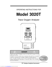
Teledyne 3020T Operating Instructions Manual (73 pages)
Trace Oxygen Analyzer
Brand:
Teledyne
| Category:
Oxygen Equipment
| Size: 1.6 MB
Table of Contents
Table of Contents
4
1 Introduction
7
Overview
7
Typical Applications
7
Main Features of the Analyzer
7
Model Designations
8
Operator Interface
9
UP/DOWN Switch
10
ESCAPE/ENTER Switch
10
Displays
11
Recognizing Difference between LCD & VFD
11
Electrical Connector Panel
11
Gas Connector Panel
13
2 Operational Theory
14
Introduction
14
Micro-Fuel Cell Sensor
15
Principles of Operation
15
Anatomy of a Micro-Fuel Cell
16
Electrochemical Reactions
17
The Effect of Pressure
18
Calibration Characteristics
18
Sample System
19
Electronics and Signal Processing
20
Temperature Control
22
3 Installation
23
Unpacking the Analyzer
23
Mounting the Analyzer
23
Electrical Connections
25
Primary Input Power
26
Fuse Installation
26
Analog Outputs
26
Alarm Relays
28
Digital Remote Cal Inputs
29
Range ID Relays
31
Network I/O
31
RS-232 Port
31
Remote Sensor and Solenoid Valves
32
Installing the Micro-Fuel Cell
33
Gas Connections
34
Testing the System
36
4 Operation
37
Introduction
37
Using the Controls
37
Mode/Function Selection
38
Analysis Mode
38
Setup Mode
38
Data Entry
40
Enter
40
Escape
40
The AUTO-CAL Function
41
The PWD Function
41
Entering the Password
42
Installing or Changing the Password
43
The LOGOUT Function
44
The VERSION Screen
44
The SELF TEST Function
45
The ZERO and SPAN Functions
45
Zero Cal
46
Auto Mode Zeroing
46
Manual Mode Zeroing
47
Cell Failure
48
Span Cal
48
Auto Mode Spanning
48
Manual Mode Spanning
49
The ALARMS Function
50
The RANGE Function
52
Setting the Analog Output Ranges
52
Fixed Range Analysis
53
The CONTRAST Function
54
The STANDBY Function
54
The Analysis Mode
55
Maintenance
57
Routine Maintenance
57
Major Internal Components
57
Cell Replacement
58
Storing and Handling Replacement Cells
59
When to Replace a Cell
59
Removing the Micro-Fuel Cell
60
Installing a New Micro-Fuel Cell
62
Cell Warranty
63
Fuse Replacement
63
System Self Diagnostic Test
64
Appendix A-1 Specifications
67
Recommended 2-Year Spare Parts List
69
Drawing List
70
Advertisement
Related Products
Teledyne 3160
Teledyne 319R
Teledyne 356WA
Teledyne 329R
Teledyne 3020P
Teledyne 3020M
Teledyne 3020
Teledyne 3000MB
Teledyne 3000ZA-3X
Teledyne WaveStation 3000
Teledyne Categories
Measuring Instruments
Analytical Instruments
Digital Camera
Test Equipment
Laboratory Equipment
More Teledyne Manuals
Login
Sign In
OR
Sign in with Facebook
Sign in with Google
Upload manual
Upload from disk
Upload from URL