Table of Contents
Advertisement
Quick Links
OPERATING INSTRUCTIONS FOR
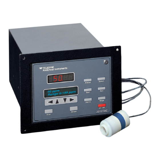
Model 3010TAC
Trace Oxygen Analyzer
Flush Mount Control Unit, PN D-66192A
CENELEC Type Remote Probe, PN C-66336
Intrinsic Safe Barriers Assy., PN C-67564
HIGHLY TOXIC AND OR FLAMMABLE LIQUIDS OR GASES MAY BE PRESENT IN THIS
MONITORING SYSTEM.
PERSONAL PROTECTIVE EQUIPMENT MAY BE REQUIRED WHEN SERVICING THIS SYSTEM.
HAZARDOUS VOLTAGES EXIST ON CERTAIN COMPONENTS INTERNALLY WHICH MAY PER-
SIST FOR A TIME EVEN AFTER THE POWER IS TURNED OFF AND DISCONNECTED.
ONLY AUTHORIZED PERSONNEL SHOULD CONDUCT MAINTENANCE AND/OR SERVICING.
BEFORE CONDUCTING ANY MAINTENANCE OR SERVICING CONSULT WITH AUTHORIZED
SUPERVISOR/MANAGER.
DANGER
Teledyne Analytical Instruments
Oxygen Analyzer
P/N M66394
11/22/99
ECO#:99-0459
i
Advertisement
Chapters
Table of Contents

Related Manuals for Teledyne 3010TAC


Summary of Contents for Teledyne 3010TAC
- Page 1 Oxygen Analyzer OPERATING INSTRUCTIONS FOR Model 3010TAC Trace Oxygen Analyzer Flush Mount Control Unit, PN D-66192A CENELEC Type Remote Probe, PN C-66336 Intrinsic Safe Barriers Assy., PN C-67564 DANGER HIGHLY TOXIC AND OR FLAMMABLE LIQUIDS OR GASES MAY BE PRESENT IN THIS MONITORING SYSTEM.
- Page 2 Any safeguards required such as locks, labels, or redundancy, must be provided by the user or specifically requested of Teledyne at the time the order is placed.
- Page 3 Oxygen Analyzer Table of Contents Specific Model Information ........iv Preface ..............v Part I: Control Unit, Model TAC ..... Part I: 1-1 Part II: Intrinsic Safe Barriers and Remote Probe ......Part II: 1-1 Appendix ............A-1 Teledyne Analytical Instruments...
-
Page 4: Appendix
Model 3010TAC complies with all of the requirements of the Common- wealth of Europe (CE) for Radio Frequency Interference and Electromagnetic Interference (RFI/EMI) protection. -
Page 5: Typical Applications
Unit, designed for nonhazardous areas only, remotely controls a specially designed Analysis Unit, or remote probe, that can operate in a hazardous area. 3010TAC Analyzers meet or exceed all of the requirements of the Commonwealth of Europe (CE) for Radio Frequency Interference and Electromagnetic Interference (RFI/EMI) protection, and Low Voltage Directive (LVD). - Page 6 Instruments to be sure of a match. Where an underscore (_) appears in a model number, the unit has more than one application. For example, 3010T_C means that the same unit is part of the 3010TAC and the 3010TBC models.
-
Page 7: Main Features Of The Analyzer
Oxygen Analyzer Main Features of the Analyzer The Model 3010TAC series Oxygen Analyzers are sophisticated yet simple to use. The main features of these analyzers include: • A 2-line alphanumeric display screen, driven by microprocessor electronics, that continuously prompts and informs the operator. - Page 8 Model 3010TAC Model 3010TAC complies with all of the requirements of the Commonwealth of Europe (CE) for Radio Frequency Interference, Electromagnetic Interference (RFI/EMI), and Low Voltage Directive (LVD). The Analysis Unit is Intrinsically safe and CENELEC approved. The Control Unit is suitable for general purpose areas. The probe is CENELEC approved (certification code EEXIA IICT6).
- Page 9 Unit Part I: Control OPERATING INSTRUCTIONS 3010TAC Model Oxygen Analyzer Part I: Control Unit Flush Panel Mount Part Numbers: D-66192A Part I: i Teledyne Analytical Instruments...
-
Page 10: Table Of Contents
Model 3010TAC Oxygen Analyzer Table of Contents 1 Introduction 1.1 Overview ................ 1-1 1.2 Control Unit Front Panel ..........1-1 1.3 Recognizing Difference Between LCD & VFD ....1-3 1.4 Control Unit Rear Panel ..........1-3 2 Operational Theory 2.1 Introduction ..............2-1 2.2 Electronics and Signal Processing ........ - Page 11 4.7 The Analyze Function ............ 4-20 4.8 Signal Output ..............4-20 5 Maintenance 5.1 Fuse Replacement............5-1 5.2 System Self Diagnostic Test ........... 5-2 5.3 Major Internal Components ..........5-3 5.4 Cleaning ................ 5-4 Part I: iii Teledyne Analytical Instruments...
- Page 12 Model 3010TAC Oxygen Analyzer iv: Part I Teledyne Analytical Instruments...
-
Page 13: Introduction
Unit, is a versatile microprocessor-based instrument for detecting trace amounts of oxygen in a variety of gases. Part I, this part, of this manual covers the Model 3010TAC General Purpose flush-panel and/or rack-mount Control Unit. (The Remote Probe is covered in Part III of this manual.) The Control Unit is for indoor use in a nonhazardous environment only. - Page 14 1 Introduction Model 3010TAC Figure 1-1: Front of Unmounted Control Unit Function Keys: Six touch-sensitive membrane switches are used to change the specific function performed by the analyzer: • Analyze Perform analysis for oxygen content of a sample gas. •...
-
Page 15: Recognizing Difference Between Lcd & Vfd
The Control Unit rear panel, shown in Figure 1-2, contains the electrical connectors for external inputs and outputs. The input/output functions are described briefly here and in detail in the Installation chapter of this manual. Part I: 1-3 Teledyne Analytical Instruments... - Page 16 1 Introduction Model 3010TAC Figure 1-2: Model 3010TAC Rear Panel • Power Connection Universal AC power source. • Analog Outputs 0-1 V dc concentration and 0-1 V dc range ID. Isolated 4-20 mA dc and 4-20 mA dc range ID.
- Page 17 Not implemented at this printing. Note: If you require highly accurate Auto-Cal timing, use external Auto-Cal control where possible. The internal clock in the Model 3010TAC is accurate to 2-3 %. Accordingly, internally scheduled calibrations can vary 2-3 % per day. Part I: 1-5...
- Page 18 1 Introduction Model 3010TAC 1-6: Part I Teledyne Analytical Instruments...
-
Page 19: Operational Theory
Part I: Control Unit Operational Theory Introduction The Model 3010TAC Oxygen Analyzer Control Unit uses an 8031 microcontroller with 32 kB of RAM and 128 kB of ROM to control all signal processing, input/output, and display functions for the Model 3010TAC analyzer. - Page 20 2 Operational Theory Model 3010TAC Figure 2-1: Block Diagram of the 3010TAC 2-2: Part I Teledyne Analytical Instruments...
- Page 21 4-20 mA dc and the 0-1 V dc analog concentra- tion signal outputs, and the analog range ID outputs. The microprocessor monitors the power supply, and activates the system failure alarm if a malfunction is detected. Part I: 2-3 Teledyne Analytical Instruments...
- Page 22 2 Operational Theory Model 3010TAC 2-4: Part I Teledyne Analytical Instruments...
-
Page 23: Installation
Immediately report any damage to the shipping agent. Mounting the Control Unit The Model 3010TAC Control Unit is for indoor use in a general purpose area. It is NOT for hazardous environments of any type. The standard model is designed for flush panel mounting. Figure 3-1 is an illustration of a Model 3010 standard Control Unit front panel and mounting bezel. - Page 24 3 Installation Model 3010TAC Figure 3-1: Front Panel of the Model 3010TAC Control Unit Figure 3-2: Single and Dual 19" Rack Mounts All operator controls are mounted on the control panel, which is hinged on the left edge and doubles as a door to provide access to the internal components of the instrument.
-
Page 25: Electrical Connections
Figure 3-4 shows the Control Unit rear panel. Connections for power, communications, and other system interfaces Figure 3-4: Rear Panel of the Model 3010TAC Control Unit For safe connections, no uninsulated wiring should be able to come in contact with fingers, tools or clothing during normal operation. -
Page 26: Primary Input Power
3 Installation Model 3010TAC CAUTION: Use Shielded Cables. Also, use plugs that provide excellent EMI/RFI protection. The plug case must be connected to the cable shield, and it must be tightly fastened to the analyzer with its fastening screws. Ultimately, it is the installer who ensures that the connections provide adequate EMI/RFI sielding. - Page 27 • Can be configured as latching or nonlatching. • Can be configured out (defeated). Threshold Alarm 2: • Can be configured as high (actuates when concen- tration is above threshold), or low (actuates when concentration is below threshold). Part I: Teledyne Analytical Instruments...
- Page 28 3 Installation Model 3010TAC • Can be configured as failsafe or nonfailsafe. • Can be configured as latching or nonlatching. • Can be configured out (defeated). System Alarm: Actuates when DC power supplied to circuits is unacceptable in one or more parameters. Perma- nently configured as failsafe and latching.
- Page 29 Cal Contact Cal Contact Remote Calibration Protocol: To properly time the Digital Remote Cal Inputs to the Model 3010TAC Analyzer, the customer's controller must monitor the Cal Relay Contact. When the contact is OPEN, the analyzer is analyzing, the Remote Cal Inputs are being polled, and a zero or span command can be sent.
- Page 30 At this printing, this port is not yet functional. It is to be used for future options to the instrument. Pins 13 (+) and 29 (–). Remote Valve Connections: The 3010TAC is a single-chassis instrument, which has no Remote Valve Unit. Instead, the Remote Valve connections are used as a method for directly controlling external sample/ zero/span gas valves.
-
Page 31: Rs-232 Port
• Which alarms—if any—are tripped (AL–x ON). Each status output is followed by a carriage return and line feed. Three input functions using RS-232 have been implemented to date. They are described in Table 3-5. Part I: Teledyne Analytical Instruments... -
Page 32: Remote Probe Connection
Toggling input. Stops/Starts any status message output from the RS-232, until st<enter> is sent again. The RS-232 protocol allows some flexibility in its implementation. Table 3-6 lists certain RS-232 values that are required by the 3010TAC implementation. Table 3-6: Required RS-232 Options... -
Page 33: Testing The System
Check the integrity and accuracy of all electrical connections. Make sure there are no exposed conductors Power up the system, and test it by performing the following operations: 1. Repeat the Self-Diagnostic Test as described in chapter 4, section 4.3.5. Part I: 3-11 Teledyne Analytical Instruments... - Page 34 3 Installation Model 3010TAC 3-12: Part I Teledyne Analytical Instruments...
-
Page 35: Operation
If you choose not to use password protection, the default password is automatically displayed on the password screen when you start up, and you simply press Enter for access to all functions of the analyzer. Part I: 4-1 Teledyne Analytical Instruments... -
Page 36: Using The Data Entry And Function Buttons
4 Operation Model 3010TAC Using the Data Entry and Function Buttons Data Entry Buttons: The < > arrow buttons select options from the menu currently being displayed on the VFD screen. The selected option blinks. When the selected option includes a modifiable item, the arrow buttons can be used to increment or decrement that modifiable item. -
Page 37: The System Function
MUST enter the UNIQUE password to gain access to set-up functions which alter the instrument's operation, such as setting the instrument span or zero setting, adjusting the alarm setpoints, or defining analysis ranges. Part I: 4-3 Teledyne Analytical Instruments... -
Page 38: Tracking The O Readings During Calibration
4 Operation Model 3010TAC After a password is assigned, the operator must log out to activate it. Until then, anyone can continue to operate the instrument without entering the new password. Only one password can be defined. Before a unique password is assigned, the system assigns TETAI by default. -
Page 39: Setting Up An Auto-Cal
Note: If you require highly accurate Auto-Cal timing, use external Auto-Cal control where possible. The internal clock in the Model 3010TAC is accurate to 2-3 %. Accordingly, internally scheduled calibrations can vary 2-3 % per day. To setup an Auto–Cal cycle: Choose System from the Function buttons. -
Page 40: Password Protection
4 Operation Model 3010TAC Span OFF Nxt: 0d 0h Zero OFF Nxt: 0d 0h ), then press Enter again. (You Press < > arrows to blink Span Zero won’t be able to set OFF to ON if a zero interval is entered.) A Span Every ... -
Page 41: Installing Or Changing The Password
Change Password? <ENT>=Yes <ESC>=No Press Enter to change the password (either the default TBEAI or the previously assigned password), or press Escape to keep the existing pass- word and move on. Part I: 4-7 Teledyne Analytical Instruments... - Page 42 4 Operation Model 3010TAC If you chose Enter to change the password, the password assignment screen appears. T ET A I <ENT> To Proceed A A A A A <ENT> To Proceed Enter the password using the < > arrow keys to move back and forth...
-
Page 43: Logout
Password Reentered 4.3.5 System Self-Diagnostic Test The Model 3010TAC has a built-in self-diagnostic testing routine. Pre- programmed signals are sent through the power supply, output board and sensor circuit. The return signal is analyzed, and at the end of the test the status of each function is displayed on the screen, either as OK or as a number between 1 and 3. -
Page 44: Version Screen
4 Operation Model 3010TAC TRAK/HLD Auto—Cal PSWD Logout More Use the < > arrow keys to blink More, then press Enter. Version Self—Test Use the < > arrow keys again to move the blinking to the Self–Test function. The screen will follow the running of the diagnostic. -
Page 45: The Zero And Span Functions
If the flow is very low, to ensure a accurate readout, you have to either have 1/4” dia., 12” in length minimum exhaust tube or set the flow to 1.2 SLPM or higher. Part I: 4-11 Teledyne Analytical Instruments... -
Page 46: Zero Cal
4 Operation Model 3010TAC If you are using password protection, you will need to enter your password to gain access to either of these functions. Follow the instructions in sections 4.3.3.2 or 4.3.3.3 to enter your password. Once you have gained clearance to proceed, you can enter the Zero or Span function. -
Page 47: Manual Mode Zeroing
4.4.1.3 Cell Failure Cell failure in the 3010TAC is usually associated with inability to zero the instrument down to a satisfactorily low ppm reading. When this occurs, the 3010TAC system alarm trips, and the LCD displays a failure message. -
Page 48: Span Cal
4 Operation Model 3010TAC 4.4.2 Span Cal The Span button on the front panel is used to span calibrate the ana- lyzer. Span calibration can be performed using the automatic mode, where an internal algorithm compares consecutive readings from the sensor to determine when the output matches the span gas concentration. -
Page 49: Manual Mode Spanning
It is a sensitive indicator of stability. #### % Span Slope=#### ppm/s When the value displayed on the screen is sufficiently stable, press Enter. (Generally, when the reading changes by 1 % or less of Part I: 4-15 Teledyne Analytical Instruments... -
Page 50: Span Failure
Consider this before replacing the cell. The Alarms Function The Model 3010TAC is equipped with 2 fully adjustable concentration alarms and a system failure alarm. Each alarm has a relay with a set of form C contacts rated for 3 amperes resistive load at 250 V ac. See figure in chapter 3, Installation and/or the Interconnection Diagram included at the back of this manual for relay terminal connections. - Page 51 4.3.3 to enter your password. Once you have clearance to proceed, enter the Alarm function. Press the Alarm button on the front panel to enter the Alarm function. Make sure that AL–1 is blinking. AL—1 AL—2 Choose Alarm Part I: 4-17 Teledyne Analytical Instruments...
-
Page 52: The Range Function
0–1,000 ppm High 0–10,000 ppm. The Model 3010TAC is set at the factory to default to autoranging. In this mode, the microprocessor automatically responds to concentration changes by switching ranges for optimum readout sensitivity. If the current 4-18: Part I... -
Page 53: Setting The Analog Output Ranges
10,000 ppm. 4.6.2 Fixed Range Analysis The autoranging mode of the instrument can be overridden, forcing the analyzer DC outputs to stay in a single predetermined range. Part I: 4-19 Teledyne Analytical Instruments... -
Page 54: The Analyze Function
The Analyze Function When the Analyze function is active, the 3010TAC is monitoring the sample gas currently flowing in the Analysis Unit cell block. All undefeated alarms are ready to activate should their respective setpoints be crossed. - Page 55 They generate a steady preset voltage (or current when using the current outputs) to represent a particular range. The following table gives the range ID output for each analysis range: Range Voltage (V) Current (mA) 0.25 0.50 0.75 CAL (0-25%) 1.00 Part I: 4-21 Teledyne Analytical Instruments...
- Page 56 4 Operation Model 3010TAC IMPORTANT: In the event of loss of flow through the analyzer, if the vent is vented to a location of high oxygen content, oxygen will back diffuse through the vent line and in most cases quickly saturate the cell with oxygen which...
-
Page 57: Maintenance
1. Place small screwdriver in notch, and pry cover off, as shown in Figure 5-1. Figure 5-1: Removing Fuse Block from Housing 2. To change between American and European fuses, remove the single retaining screw, flip Fuse Block over 180 degrees, and replace screw. Part I: 5-1 Teledyne Analytical Instruments... -
Page 58: System Self Diagnostic Test
5 Maintenance Model 3010TAC Oxygen Analyzer 3. Replace fuse as shown in Figure 5-2. 4. Reassemble Housing as shown in Figure 5-1. American Fuses European Fuses Figure 5-2: Installing Fuses System Self Diagnostic Test 1. Press the System button to enter the system mode. -
Page 59: Major Internal Components
The Front Panel Display Board is accessed by unlatching and swinging open the front panel, as described earlier. Other electronic components are accessed by removing four rear panel screws and sliding out the entire chassis. See Figure 5-4, below. Part I: 5-3 Teledyne Analytical Instruments... -
Page 60: Cleaning
5 Maintenance Model 3010TAC Oxygen Analyzer Figure 5-4: Rear-Panel Screws To detach the rear panel, remove only those ten screws marked with an . Cleaning If instrument is unmounted at time of cleaning, disconnect the instru- ment from the power source. Close and latch the front-panel access door. - Page 61 Part II: Analysis Unit OPERATING INSTRUCTIONS Model 3010TAC Oxygen Analyzer Part II Intrinsic Safe Barriers Remote Probe CENELEC Type Part Number C-67564 Part II: i Teledyne Analytical Instruments...
- Page 62 Model 3010TAC Oxygen Analyzer Table of Contents 1 Introduction 1.1 Overview ................ 1-1 1.2 Intrinsic Safe Barriers ............. 1-1 1.3 Area Classification ............1-2 1.4 Cell Housing/Probe ............1-2 2 Operational Theory 2.1 Introduction ..............2-1 2.2 Micro-Fuel Cell Sensors ..........2-1 2.2.1 Principles of Operation ..........
-
Page 63: Introduction
Part II: Analysis Unit Introduction Overview The Analytical Instruments Model 3010TAC Remote Probe is a versatile remotely controlled instrument for detecting trace amounts of oxygen (0-10 ppm to 0-250 ppm) in a variety of background gases. Details are recorded in Specifications in the Appendix to this manual. -
Page 64: Area Classification
1 Introduction Model 3010TAC CAUTION: Bypassing the barriers in any way nullifies their effect, and conditions which prompted their use will prevail. If the instrument is used under any conditions contrary to the intrinsic safety design, the user assumes all risk. -
Page 65: Operational Theory
Control Unit, covered in Part I of this manual. Micro-Fuel Cell Sensor 2.2.1 Principles of Operation The oxygen sensors used in the Model 3010TAC series are Micro- Fuel Cells designed and manufactured by Analytical Instruments. They are sealed plastic disposable electrochemical transducers. -
Page 66: Anatomy Of A Micro-Fuel Cell
2 Operational Theory Model 3010TAC being analyzed. The Micro-Fuel Cell is therefore a hybrid between a battery and a true fuel cell. (All of the reactants are stored externally in a true fuel cell.) 2.2.2 Anatomy of a Micro-Fuel Cell A Micro-Fuel Cell (MFC) is a cylinder only 1¼... -
Page 67: Electrochemical Reactions
The current is propor- tional to the amount of oxygen reaching the cathode. It is measured and used to determine the oxygen concentration in the gas mixture. Part II: 2-3 Teledyne Analytical Instruments... -
Page 68: The Effect Of Pressure
2 Operational Theory Model 3010TAC The overall reaction for the fuel cell is the SUM of the half reactions above, or: 2Pb + O 2PbO (These reactions will hold as long as no gaseous components capable of oxidizing lead—such as iodine, bromine, chlorine and fluorine—are present in the sample.) -
Page 69: Micro-Fuel Cell "Class
Nominal output in air is 0.5 mA, and 90 % response time is 7 s. Expected life is 12 months. Part II: 2-5 Teledyne Analytical Instruments... - Page 70 2 Operational Theory Model 3010TAC 2-6: Part II Teledyne Analytical Instruments...
-
Page 71: Installation
Oxygen Analyzer Part II: Analysis Unit Installation Installation of the Model 3010TAC Analyzer includes: 1. Unpacking, mounting, and interconnecting the Control Unit and the Analysis Unit 2. Making gas connections to the system 3. Making electrical connections to the system 4. -
Page 72: Installing The Micro-Fuel Cell
3 Installation Model 3010TAC If you use your own gas control valves, use the interconnect diagram in Figure 3-5 for the valves. The sensor and thermistor remain connected as in Figure 3-4, above. Installing the Micro-Fuel Cell The Micro-Fuel Cell is not installed in the cell block when the instrument is shipped. -
Page 73: Intrinsic Safety Barriers
The barrier strips are housed in an approved bulkhead mountable barrier box (P/N E324). Refer to drawing D66193 for terminal connection. Figure 3-4: Control Unit (CU) to Analysis Unit (AU) Connector Cable Part II: Teledyne Analytical Instruments... - Page 74 3 Installation Model 3010TAC D - SUB CONNECTOR’S DESCRIPTION PIN # Description + Range ID 4-20 mA - Range ID 4-20 mA + Output 4-20 mA - Output 4-20 mA - Output 0-1 V + Range ID 0-1 V Network +...
- Page 75 Zero Solenoid Sample Solenoid Return 3.5 Remote Probe Connection The Models 3010TAC are split architecture (dual-chassis) instru- ments, which have a Remote Probe, or Analysis Unit. The remote probe is for receiving the oxygen sensor and thermistor signals. Remote Probe 9-pin Connector...
- Page 76 3 Installation Model 3010TAC 3-6: Part II Teledyne Analytical Instruments...
-
Page 77: Maintenance
Cell failure in the 3010T is usually characterized inability to zero the instrument down to a satisfactorily low ppm reading. When this occurs, the 3010TAC system alarm trips, and the VFD displays a failure message. ppm Anlz CELL FAIL/ ZERO HIGH Before replacing the cell: a. -
Page 78: Installing A New Micro-Fuel Cell
Model 3010TAC 4.2.1 Installing a New Micro-Fuel Cell It is important to minimize the amount of time that a Teledyne Trace Oxygen Sensor is exposed to air during the installation process. The quicker the sensor can be installed into the unit, the faster your TAI O... -
Page 79: Cell Warranty
Part II: Analysis Unit 4.2.2 Cell Warranty The Micro-Fuel cell used in the standard Model 3010TAC is the L-2C for Trace Analysis. Check Specific Model Information in the front matter of this manual for cell class in your unit, if nonstandard, as this will affect cell life and warranty data. - Page 80 4 Maintenance Model 3010TAC DAC A (0–1 V Concentration) DAC B (0–1 V Range ID) Both Failed Preamp Zero too high Amplifier output doesn't match test input Both Failed 4-4: Part II Teledyne Analytical Instruments...
- Page 81 Oxygen Analyzer Appendix OPERATING INSTRUCTIONS 3010TAC Models Oxygen Analyzers Appendix Flush Mount Control Unit, PN D66192A CENELEC Type Analysis Unit, PN C66336 Teledyne Analytical Instruments...
- Page 82 Appendix Model 3010TAC Contents A-1 Model 3010TAC Specifications ........A-3 A-2 Recommended 2-Year Spare Parts List ......A-5 A-3 Drawing List ..............A-6 A-4 Material Safety Data Sheet ..........A-7 Teledyne Analytical Instruments...
-
Page 83: Model 3010Tac Specifications
Two adjustable concentration threshold alarms with fully programmable setpoints. Diagnostics: Start-up or on-demand, comprehensive, self testing function initiated by keyboard. Displays: 2 line by 20 alphanumeric, VFD screen, and one 5 digit LED display. Digital Interface: Full duplex RS-232 communications port. Teledyne Analytical Instruments... - Page 84 Appendix Model 3010TAC Power:General Purpose Control Unit Universal power supply 85-250 V ac, 47-63 Hz. Operating Temperature: 0-50 °C EMF/RFI: Immunity and Emissions designed to meet EN 50081-1 EN 50082-2. LVD Accuracy: ±2% of full scale at constant temperature. ±5% of full scale over operating temperature range, on factory default analysis ranges, once thermal equilibrium has been achieved.
-
Page 85: Recommended 2-Year Spare Parts List
(if available) and the model and serial number of the instru- ment for which the parts are intended. Orders should be sent to: TELEDYNE Analytical Instruments 16830 Chestnut Street City of Industry, CA 91749-1580 Phone (626) 934-1500, Fax (626) 961-2538... -
Page 86: Drawing List
D-66193: Sensor Block Interconnection Diagram C-66899: Sensor Block Outline Diagram, Top 4 Probe C-67564 Safety Barrier Housing Assembly NOTE: The MSDS on this material is available upon request through the Teledyne Environmental, Health and Safety Coordinator. Contact at (626) 934-1592 Teledyne Analytical Instruments... -
Page 87: Material Safety Data Sheet
Product Name: Micro-Fuel Cells and Super Cells, all classes except A-2C, A-3, and A-5. Electrochemical Oxygen Sensors, all classes except R-19. Micro-Fuel Cells, all classes. Manufacturer: Teledyne Analytical Instruments Address: 16830 Chestnut Street, City of Industry, CA 91749 Phone: (626) 934-1500... - Page 88 Appendix Model 3010TAC Section IV – Fire and Explosion Hazard Data Flash Point: Flammable Limits: LEL: UEL: Extinguishing Media: Use extinguishing media appropriate to surrounding fire conditions. No specific agents recommended. Special Fire Fighting Wear NIOSH/OSHA approved self-contained breathing Equipment: apparatus and protective clothing to prevent contact with skin and eyes.
- Page 89 If there is liquid around the cell while in the instrument, wear eye and hand protection. Cleanup Procedures: Wipe down the area several times with a wet paper towel. Use a fresh towel each time. Contaminated paper towels are considered hazardous waste. Teledyne Analytical Instruments...
- Page 90 NOTE: The above information is believed to be correct and is offered for your information, consideration, and investigation. It should be used as a guide. Teledyne Analytical Instruments shall not be held liable for any damage resulting from handling or from contact with the above product.