Table of Contents
Advertisement
Owner's Manua
Read this first. It explains the basic things you need
to know in order to use the V-1SDI.
PDF Manual
(download from the Web)
5 Remote Control Guide
This manual covers remote control of the V-1SDI via
MIDI, menu items, and RS-232 commands.
Before using the V-1SDI, ensure that its system program is at the most recent version. For information on available
upgrades for the system program, see the Roland website (http://proav.roland.com). You can check the system
program version by pressing and holding the [SETUP] button g "VERSION" at the SETUP menu (page 16/16).
l (this document)
To obtain the PDF manual
1.
Enter the following URL in your computer.
http://proav.roland.com
I
2.
Go to the V-1SDI product page and click
the "Support" tab.
Copyright © 2016 ROLAND CORPORATION
Advertisement
Table of Contents

Related Manuals for Roland V-1SDI


Summary of Contents for Roland V-1SDI
- Page 1 MIDI, menu items, and RS-232 commands. Copyright © 2016 ROLAND CORPORATION Before using the V-1SDI, ensure that its system program is at the most recent version. For information on available upgrades for the system program, see the Roland website (http://proav.roland.com). You can check the system...
-
Page 2: Table Of Contents
Checking the Included Items The V-1SDI includes the following items. Please take a moment to confirm that all of these items have been included with the V-1SDI. If you find that any item is missing, contact the nearest authorized Roland distributor in your country. -
Page 3: Using The Unit Safely
Use only the attached power cord. Also, the Refer all servicing to your retailer, the nearest supplied power cord must not be used with Roland Service Center, or an authorized Roland any other device. distributor, as listed on the “Information. ”... - Page 4 Before using the unit in overseas, consult with your retailer, the nearest Roland Service Center, Keep small items out of the reach of children or an authorized Roland distributor, as listed on the “Information. ” To prevent accidental ingestion of the parts listed below, always keep them out of the reach of small children.
-
Page 5: Important Notes
To protect yourself against the irretrievable loss of this unit, or switch them off. important data stored in the unit, use V-1SDI RCS • When moved from one location to another where the dedicated software (p. 31) to make backups. -
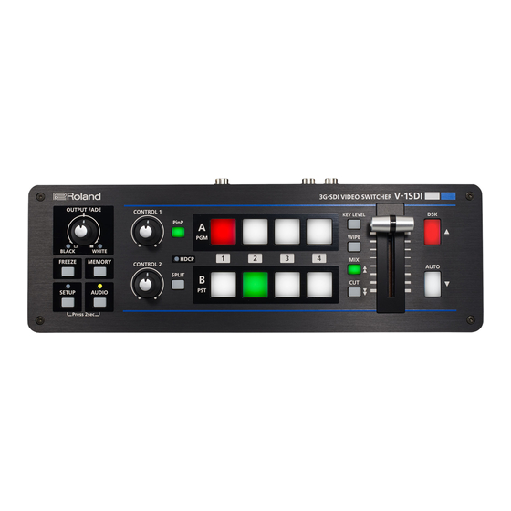
Page 6: Panel Descriptions
Panel Descriptions Top Panel/Front Panel [OUTPUT FADE] Knob [PinP] and [SPLIT] Buttons p. 21, 26 p. 22 This performs a fade-in or fade-out for the main These turn PinP, split, and other video compositing output video, and adjusts the volume level for on and off. -
Page 7: [Freeze] Button
Never obstruct the cooling-fan exhaust port. NOTE Obstructing the exhaust port might result in a temperature rise inside the V-1SDI and lead to malfunction due to heat. [WIPE], [MIX] ( ), and [CUT] ( ) Buttons p. 12, 18 These select video transition effects. -
Page 8: Rear Panel (For Equipment Connections)
You use V-1SDI RCS dedicated software Cord hook the cord hook, as shown in the illustration. to operate the V-1SDI remotely from a For information on how to attach the cord hook, refer to “Attaching connected computer. the Power Cord Hook” (p. 10). - Page 9 Panel Descriptions * The V-1SDI is designed to radiate heat from the entire rear panel. Accordingly, the rear panel might become hot during use, but this is not a malfunction. HDMI IN 4 Connector p. 14, 15 HDMI IN 3 Connector p.
-
Page 10: Side Panel (For Equipment Connections)
[FORMAT] Switch p. 14 This switches the input/output format. * Before operating the [FORMAT] switch, be sure the power to the V-1SDI is turned off. Attaching the Power Cord Hook Detach the retainer screw indicated in the figure. RS-232 Connector p. -
Page 11: Basic Operation
The Auto Off function is turned off. Power is MEMO not turned off automatically. 5 The power to the V-1SDI turns off automatically if Quit the menu (p. 12). a set interval elapses with no operation performed (Auto Off function). -
Page 12: Using The Menus
Basic Operation Using the Menus This explains how to display menus and make settings for video and audio, and for the V-1SDI itself. * Menus are shown only on the monitor connected to the MULTI-VIEW connector (HDMI) (p. 8). Displaying/Exiting Menus... -
Page 13: Saving/Recalling Settings (Memory)
You can take the current settings, including video and audio settings and the state of the operation panel, and save them as a single set in memory, for later recall and use when needed. The V-1SDI is provided with eight memories. -
Page 14: Video Input/Output Settings
This is optimal for video that 5 Before operating the [FORMAT] switch, be sure the contains little movement. power to the V-1SDI is turned off. To set the conversion method, go to the SETUP menu, and at SYSTEM (page 14/16), use “DEINTERLACE MODE”... -
Page 15: Adjusting Output Video
Adjusting HDMI Input Video on Channel 4 You can adjust the output video to match the equipment receiving the output from the V-1SDI. You can adjust image quality and set the EDID value MEMO for video input via HDMI IN 4. -
Page 16: Assigning A Video Source To Channel 3
Three types of view modes are available for the HDMI input for channel 3 is set to “AUTO” (automatic V-1SDI’s preview output. You can set the view mode detection of the connection). When devices are individually for the PVW connector (SDI) and the connected to both the SDI IN 3 connector and the MULTI-VIEW connector (HDMI). -
Page 17: Inputting Copyright-Protected (Hdcp) Video
Blu-ray Disc player or the like, you make the setting for enabling HDCP input. * The V-1SDI must be connected to an HDCP compatible display for HDCP protected video to be connected. Display the SETUP menu (p. 12), then select “HDCP.”... -
Page 18: Video Operations
Video Operations Switching the Video You can switch the video input to bus A and to bus B of the video mixer. About the Operation Mode for Video Switching Using the PGM/PST Mode Transitions Video at the PGM position is always output. At the PST position you select the video you want to output Two operation modes are available for video next (standby), then switch the video. -
Page 19: Switching In The A/B Mode
Video Operations Move the A/B fader in the direction opposite to Switching in the A/B Mode the direction in step 1. The video on the bus toward which the A/B fader is flipped is output. Use the [A-1] through [A-4] and [B-1] through [B-4] buttons to select the video to input on bus A and bus B. -
Page 20: Switching Automatically (Auto Scan)
Video Operations Freezing Input Video (Freeze) Switching Automatically (Auto Scan) The video on channels 1 through 4 is switched This temporarily pauses the incoming video. automatically in sequence. You can apply transition effects and perform video compositing during a video freeze. MEMO 5 Any channels carrying no video input are skipped. -
Page 21: Applying A Fade To The Main Output Video
Applying a Fade to the Main Output Video (Output Fade) You can apply a fade to the V-1SDI’s main output video. This lets you make the main output video fade to a black (or white) picture at times when you want to suppress video output, such as during intervals in a presentation, event or band performance. -
Page 22: Video Composition Operations
Video Composition Operations You can composite video on bus A and video on bus B. The V-1SDI has seven built-in types of composition. Selecting a Composition Type Compositing Four Video Pictures into One Screen This selects the composition type to assign to the [PinP] or [SPLIT] button. -
Page 23: Compositing Using Picture-In-Picture
Video Composition Operations Compositing Using Picture-in-Picture This composites video in an inset screen onto a different background video. This section describes operations when in the PGM/PST mode (p. 18). Turn the [CONTROL 1] and [CONTROL 2] knobs Inset screen to adjust the display position of the inset screen. [CONTROL 1] knob This adjusts the inset screen’s display position horizontally. -
Page 24: Compositing Using Split
Video Composition Operations Compositing Using Split Compositing Using DSK This composites two video streams in a split screen. This takes video composited upstream using PinP or the like, and performs further downstream The video at the PGM (video currently being output) compositing with text or images. - Page 25 Video Composition Operations Compositing Using DSK MEMO 5 You can adjust the overall density of the text and images being composited using DSK. Go to the SETUP menu, and at DSK (page 7/16), adjust the value of “MIX LEVEL. ” 5 For the fade time used for text and images Input a logo or image.
-
Page 26: Audio Operations
8/15), make the setting using “AUDIO LED. ” * If the volume level of speaker output is unsuitable even when the volume level on the V-1SDI has been adjusted so that the AUDIO indicator and level meter light up in yellow, adjust the volume for the speakers and amplifiers. -
Page 27: Applying Effects To Audio
Audio Operations Applying Effects to Audio You can apply effects to audio that is input and output to adjust its sound quality. Applying Effects to Input Audio Delay (DELAY) This applies effects and adjusts sound quality for This outputs audio with a delay. audio input via AUDIO IN, MIC, SDI IN, and HDMI IN. -
Page 28: Applying Effects To Output Audio
Audio Operations Reverb (REVERB) Applying Effects to Output Audio This applies effects and adjusts the sound quality for This adds lingering reverberations to the audio. output audio. You can apply reverb to audio input via AUDIO IN, MIC, SDI IN, and HDMI IN. MASTER OUT (page 13/15) Display the AUDIO menu (p. -
Page 29: Interlinking Audio Output To Video Switching
Audio Operations Interlinking Audio Output to Video Switching (Audio Follow) You can associate audio with a video switch so that when the video is switched, only the audio of the output video is output, and other audio is automatically muted. You can also use Audio Follow with audio input via AUDIO IN or MIC. -
Page 30: Other Features
Returning Settings to the Factory- Preventing Unintended default State (Factory Reset) Operation (Panel Lock) You can return the values of settings on the V-1SDI to This locks operation of buttons and knobs to prevent their factory defaults. unintended operation of the V-1SDI. -
Page 31: Operating The V-1Sdi By Remote Control
Other Features Operating the V-1SDI by Remote Control You can use V-1SDI RCS dedicated software to remotely control the following functions on the V-1SDI from a computer connected via USB. 5 V-1SDI panel operations 5 Selecting transition effects 5 Audio mixer operation... -
Page 32: Appendices
Video-related problems Are the [A-1] through [A-4] and [B-1] Video whose format differs from the setting on the through [B-4] buttons flashing in V-1SDI is input. Input video that is compatible with the p. 14 white? specified format. No picture is input. -
Page 33: Transition Effects List
Appendices Transition Effects List Effect Explanation The two pictures are blended together as the video is switched. Video transitions are made with the luminance levels of the two video streams maintained unchanged. * This is an abbreviation of “full additive mix. ” The two video streams are compared, and transitions are made with display during transition starting with levels of high luminance. -
Page 34: Block Diagram
Appendices Block Diagram Video Block SDI INPUT 1 FREEZE CONV SDI INPUT 2 FREEZE CONV INPUT SDI INPUT 3 SELECT FREEZE HDMI INPUT 3 CONV EDID 1080/720p HDMI INPUT 4 EDID SCALER FREEZE 1080p 1080i FORMAT 720p MULTI- VIEWER Audio Block LEVEL GATE COMP... - Page 35 Appendices 1080p 1080i FORMAT 720p A-BUS COMPOSITION TRANSITION OUTPUT FADE CONV PinP WIPE B-BUS SPLIT CONV MULTI-VIEW MENU MULTI-VIEW CONV MULTI-VIEW REVERB MULTI-VIEW MASTER LEVEL AUDIO OUT MASTERING PHONES PHONES LEVEL REVERB LEVEL REVERB...
-
Page 36: Main Specifications
Appendices Main Specifications Roland V-1SDI: 3G-SDI Video Switcher Video Video Processing 4:2:2 (Y/Pb/Pr), 8-bit SDI INPUT 1–3 BNC x 3 * Conforms to SMPTE 424M (SMPTE 425M-AB), 292M, 259M-C Input Connectors HDMI INPUT 3–4 Type A (19 pins) x 2 * HDCP Supported * INPUT 3: SDI or HDMI selected. -
Page 37: Dimensions
Owner’s manual, AC adaptor, Power cord, Cord hook * 0 dBu=0.775 Vrms * This document explains the specifications of the product at the time that the document was issued. For the latest information, refer to the Roland website. Dimensions Unit: mm... -
Page 38: Declaration Of Conformity
DECLARATION OF CONFORMITY Compliance Information Statement Model Name : V-1SDI Type of Equipment : VIDEO SWITCHER Responsible Party : Roland Corporation U.S. Address : 5100 S. Eastern Avenue Los Angeles, CA 90040-2938 Telephone : (323) 890-3700 For the USA FEDERAL COMMUNICATIONS COMMISSION... - Page 39 For EU Countries For China...
- Page 40 Intellectual Property Right • It is forbidden by law to make an audio recording, video recording, copy or revision of a third party’s copyrighted work (musical work, video work, broadcast, live performance, or other work), whether in whole or in part, and distribute, sell, lease, perform or broadcast it without the permission of the copyright owner. • Do not use this product for purposes that could infringe on a copyright held by a third party. We assume no responsibility whatsoever with regard to any infringements of third-party copyrights arising through your use of this product. • This product can be used to record or duplicate audio or visual material without being limited by certain technological copy-protection measures. This is due to the fact that this product is intended to be used for the purpose of producing original music or video material, and is therefore designed so that material that does not infringe copyrights belonging to others (for example, your own original works) can be recorded or duplicated freely. • This product contains eParts integrated software platform of eSOL Co.,Ltd. eParts is a trademark of eSOL Co., Ltd. in Japan. • Roland is an either registered trademark or trademark of Roland Corporation in the United States and/or other countries. • Company names and product names appearing in this document are registered trademarks or trademarks of their respective owners.