Dell poweredge T430 Owner's Manual
Hide thumbs
Also See for poweredge T430:
- Owner's manual (179 pages) ,
- Getting started (2 pages) ,
- Owner's manual (194 pages)

Related Manuals for Dell poweredge T430


Summary of Contents for Dell poweredge T430
- Page 1 Dell PowerEdge T430 Owner's Manual Regulatory Model: E30S Series Regulatory Type: E30S001...
- Page 2 © 2016 Dell Inc. All rights reserved. This product is protected by U.S. and international copyright and intellectual property laws. Dell and the Dell logo are trademarks of Dell Inc. in the United States and/or other jurisdictions. All other marks and names mentioned herein may be trademarks of their respective companies.
-
Page 3: Table Of Contents
Contents 1 Dell PowerEdge T430 system overview............9 ..............10 Supported configurations on PowerEdge T430 systems ..........................10 Front panel features ........11 Front panel features of 16 x 2.5-inch hot swappable hard drive chassis ........14 Front panel features of a 8 x 3.5-inch hot swappable hard drive chassis .... - Page 4 ........................51 System Setup details ..........................52 System BIOS ........................75 iDRAC Settings utility ..........................76 Device Settings ........................76 Dell Lifecycle Controller ....................76 Embedded system management ............................77 Boot Manager ........................77 Viewing Boot Manager ......................77 Boot Manager main menu ..............................
- Page 5 ....................81 Installing the optional front bezel ............................82 System feet ......................82 Removing the system feet ......................83 Installing the system feet ..................... 84 Caster wheels (optional)—tower mode .........................84 Installing caster wheels ....................... 85 Removing caster wheels ............................87 System cover ......................
- Page 6 ....................130 Sample memory configurations ...................... 136 Removing memory modules ......................137 Installing memory modules ............................139 Cooling fans ..................... 139 Removing the internal cooling fan ....................140 Installing the internal cooling fan ................... 142 Removing the external cooling fan ....................143 Installing the external cooling fan ....................
- Page 7 ....................216 Dell Embedded System Diagnostics ..........216 Running the Embedded System Diagnostics from Boot Manager .....216 Running the Embedded System Diagnostics from the Dell Lifecycle Controller ....................... 217 System diagnostics controls 9 Jumpers and connectors ................218 .........................218 System board connectors ......................220...
- Page 8 ......................233 Troubleshooting a hard drive ....................234 Troubleshooting a storage controller ....................235 Troubleshooting expansion cards ......................236 Troubleshooting processors 11 Getting help..................... 237 ..........................237 Contacting Dell .........................237 Documentation feedback ...................237 Accessing system information by using QRL ......................238 Quick Resource Locator...
-
Page 9: Dell Poweredge T430 System Overview
Dell PowerEdge T430 system overview The Dell PowerEdge T430 is a rackable tower server that supports up to two processors based on the Intel Xeon E5-2600 v3 or v4 processor family, up to 12 DIMMs, and storage capacity of up to 16 hard drives/SSDs. -
Page 10: Supported Configurations On Poweredge T430 Systems
Supported configurations on PowerEdge T430 systems Figure 1. System view with supported configurations Front panel features The front panel provides access to the features available on the front of the server, such as the power button, NMI button, system identification tag, system identification button, and USB and VGA ports. The... -
Page 11: Front Panel Features Of 16 X 2.5-Inch Hot Swappable Hard Drive Chassis
diagnostic LEDs or the LCD panel is prominently located on the front panel. The hot swappable hard drives are accessible from the front panel. Front panel features of 16 x 2.5-inch hot swappable hard drive chassis Figure 2. Front panel features a 16 x 2.5-inch hot swappable hard drive chassis Power button NMI button System identification button... - Page 12 USB management port/iDRAC connect USB devices to the system or provide access Direct port to the iDRAC Direct features. The USB management port is USB 2.0 compliant. For more information, see the Integrated Dell Remote Access Controller User’s Guide at Dell.com/idracmanuals.
- Page 13 Indicator, button, or connector Icon Description Use the USB 3.0 port to connect USB devices to the USB port system. These ports are 9-pin, USB 3.0 compliant. Optical drive or tape-drive bay Allows you to install optical drives or tape drives. For more information on supported optical drives and tape drives, see the Optical drives and tape drives section..
-
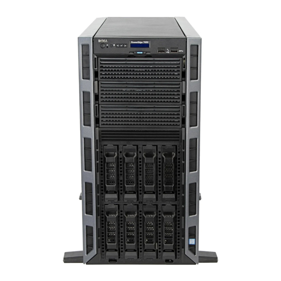
Page 14: Front Panel Features Of A 8 X 3.5-Inch Hot Swappable Hard Drive Chassis
Front panel features of a 8 x 3.5-inch hot swappable hard drive chassis Figure 3. Front panel features of a 8 x 3.5-inch hot swappable hard drive chassis Power button NMI button System identification button LCD menu buttons Information tag LCD panel... - Page 15 USB management port/iDRAC Direct port USB port Optical drive or tape-drive bay 10. Physical drives Table 3. Front panel features — 8 x 3.5-inch hot swappable hard drive chassis Indicator, button, or connector Icon Description Press the power button to turn the system on or off. Power button The indicator on the button indicates if the system is on or off.
-
Page 16: Front Panel Features Of 8 X 3.5-Inch Hot Swappable Hard Drive Chassis In Rack Mode
Indicator, button, or connector Icon Description port is USB 2.0 compliant. For more information, see the Integrated Dell Remote Access Controller User’s Guide at Dell.com/idracmanuals. Use the USB 3.0 port to connect USB devices to the USB port system. These ports are 9-pin, USB 3.0 compliant. - Page 17 USB port 10. Optical drive or tape-drive bay 11. Physical drives Table 4. Front panel features — 8 x 3.5-inch hot swappable hard drive chassis Indicator, button, or connector Icon Description Press the power button to turn the system on or off. Power button The indicator on the button indicates if the system is on or off.
- Page 18 Indicator, button, or connector Icon Description the Integrated Dell Remote Access Controller User’s Guide at Dell.com/idracmanuals. Use the video/VGA port to connect a display to the Video connector system. For more information about the supported video/VGA port, see the Technical specifications section.
-
Page 19: Front Panel Features Of 4 X 3.5-Inch Cabled Hard Drive Chassis
Front panel features of 4 x 3.5-inch cabled hard drive chassis Figure 5. Front panel features and indicators- 4 x 3.5 inch cabled hard-drive chassis Power button NMI button System identification button Information tag Diagnostic indicators USB ports... - Page 20 Optical drive or tape-drive bay Table 5. Front panel features - 4 x 3.5-inch cabled hard drive chassis Indicator, Icon Description Button, Connecto Press the power button to turn the system on or off. The indicator on the Power button indicates if the system is on or off. button NOTE: To gracefully shut down an ACPI-compliant operating system, press the power button.
-
Page 21: Lcd Panel
The LCD panel of your system provides system information, status, and error messages to indicate if the system is functioning correctly or if the system needs attention. For more information about error messages, see the Dell Event and Error Messages Reference Guide at Dell.com/ openmanagemanuals >OpenManage software. - Page 22 SEL. This enables you to match an LCD message with an SEL entry. Select Simple to view LCD error messages in a simplified user-friendly description. For more information about error messages, see the Dell Event and Error Messages Reference Guide at Dell.com/openmanagemanuals > OpenManage software. Set home Select the default information to be displayed on the Home screen.
-
Page 23: Back Panel Features
Back panel features The back panel provides access to the features available on the back of the server, such as the system identification button, power supply sockets, cable management arm connectors, iDRAC storage media, NIC ports, and USB and VGA ports. A majority of the expansion card ports can be accessed from the back panel. - Page 24 BIOS progress mode. Use the iDRAC8 Enterprise port to remotely access iDRAC. For iDRAC port more information, see the Integrated Dell Remote Access (optional) Controller User’s Guide at Dell.com/idracmanuals. Use the system identification port to connect the system status System indicator assembly through the optional cable management arm.
-
Page 25: Diagnostic Indicators
Check the System Event Log or system messages for the specific issue. For more • When the system is turned on. information about error messages, see the Dell Event and Error Messages Reference • When the system is in standby. Guide at Dell.com/openmanagemanuals > •... - Page 26 Icon Description Condition Corrective action Electrical The indicator flashes amber Check the System Event Log or system indicator if the system experiences an messages for the specific issue. If it is due electrical error (for example, to a problem with the PSU, check the LED voltage out of range, or a on the PSU.
-
Page 27: Hot Swappable Hard Drive Indicator Codes
Hot swappable hard drive indicator codes Each hard drive carrier has an activity indicator and a status indicator. The indicators provide information about the current status of the hard drive. The activity LED indicates whether hard drive is currently in use or not. -
Page 28: Nic Indicator Codes
NIC indicator codes Each NIC on the back panel has an indicator that provides information about the network activity and link status. The activity LED indicates whether the NIC is currently connected or not. The link LED indicates the speed of the connected network. Figure 9. - Page 29 CAUTION: Do not disconnect the power cord or unplug the PSU when updating firmware. If firmware update is interrupted, the PSUs will not function. You must roll back the PSU firmware by using Dell Lifecycle Controller. See Dell Lifecycle Controller User’s Guide at Dell.com/idracmanuals. Flashes green...
-
Page 30: Indicator Codes For Non-Redundant Power Supply Unit
Indicator codes for non-redundant power supply unit Press the self-diagnostic button to perform a quick health check on the non-redundant power supply unit (PSU) of the system. Figure 10. Non-redundant AC PSU status indicator and self-diagnostic button self-diagnostic button AC PSU status indicator Table 12. -
Page 31: Locating Service Tag Of Your System
Code and Service Tag are found on the front of the system by pulling out the information tag. Alternatively, the information may be on a sticker on the chassis of the system. This information is used by Dell to route support calls to the appropriate personnel. -
Page 32: Converting The System From Tower Mode To Rack Mode
CAUTION: Do not attempt to convert your system into a rack unless authorized by Dell. Only customers certified by Dell for tower to rack conversion can convert a tower system into a rack system. NOTE: For specific caution statements and procedures, see the rack installation documentation for your system at Dell.com/poweredgemanuals. - Page 33 Figure 12. Removing and installing the rack ears 1. screw for each rack ear (3) 2. rack ear (2) 3. front panel Next steps Install the system cover. Install the system in a rack. For more information, see the system’s Rack Installation Guide at Dell.com/poweredgemanuals.
- Page 34 Related links Safety instructions Before working inside your system Removing the system feet Removing caster wheels Removing the system cover Removing the control panel assembly Removing the control panel assembly cover Installing the VGA module Installing the control panel assembly cover Removing the system top cover Installing the control panel assembly Removing the VGA module...
-
Page 35: Documentation Resources
For information about iDRAC features, Dell.com/idracmanuals system configuring and logging in to iDRAC, and managing your system remotely, see the Integrated Dell Remote Access Controller User's Guide. For information about installing the Dell.com/operatingsystemmanuals operating system, see the operating system documentation. - Page 36 OpenManage Essentials, see the Dell OpenManage Essentials User’s Guide. For information about installing and Dell.com/DSET using Dell System E-Support Tool (DSET), see the Dell System E-Support Tool (DSET) User's Guide. For information about installing and Dell.com/asmdocs using Active System Manager (ASM), see the Active System Manager User’s...
- Page 37 Task Document Location by the system firmware and agents that monitor system components, see the Dell Event and Error Messages Reference Guide.
-
Page 38: Technical Specifications
Technical specifications The technical and environmental specifications of your system are outlined in this section. Chassis dimensions Figure 13. Chassis dimensions of Dell PowerEdge T430 system... -
Page 39: Chassis Weight
36 Kg (79.37 lb) PowerEdge T430 Processor specifications The PowerEdge T430 system supports up to two Intel Xeon E5-2600 v4 or Xeon E5-2600 v3 product family processors. PSU specifications The PowerEdge T430 system supports up to two AC or DC redundant power supply units (PSUs). -
Page 40: Expansion Bus Specifications
Expansion bus specifications The PowerEdge T430 system supports PCI express (PCIe) generation 3 and 2 expansion cards. The following table describes the supported expansion cards: Table 18. Supported PCI express generation 3 expansion cards PCIe Slot Processor Connection Height Length... -
Page 41: Optical Drive
Ports and connectors specifications Serial connector The serial connector connects a serial device to the system. The PowerEdge T430 system supports DB-9 Serial Port connector. Internal Dual SD Module The PowerEdge RT430 system supports two optional flash memory card slots with an internal SD... -
Page 42: Vga Ports
The Video Graphic Array (VGA) port enables you to connect the system to a VGA display. The PowerEdge T430 system with 2.5-inch and 3.5-inch hot-swappable hard-drive chassis supports two 15-pin VGA ports on the front and back panels. The PowerEdge T430 system with 3.5-inch cabled hard-drive chassis supports one 15-pin VGA port on the back panel. -
Page 43: Environmental Specifications
1280 x 1024 8, 16, 32 1440 x 900 8, 16, 32 Environmental specifications NOTE: For additional information about environmental measurements for specific system configurations, see Dell.com/environmental_datasheets. Table 24. Environmental Type Condition Temperature or Specification Temperature Maximum Temperature Gradient (Operating 20 °C/h (36 °F/h) -
Page 44: Particulate And Gaseous Contamination Specifications
Type Condition Temperature or Specification Storage Six consecutively executed shock pulses in the positive and negative x, y, and z axes (one pulse on each side of the system) of 71 G for up to 2 ms. Maximum Altitude 3,048 m (10,000 ft) Operating Storage 12,000 m (39,370 ft). -
Page 45: Expanded Operating Temperature
Non-redundant power supplies are not supported. • Cabled power supply units are not supported. • Non Dell qualified peripheral cards and/or peripheral cards greater than 25 W are not supported. NOTE: When operating in the expanded temperature range, system performance may be impacted. - Page 46 NOTE: When operating in the expanded temperature range, ambient temperature warnings may be reported on the LCD and in the System Event Log.
-
Page 47: Initial System Setup And Configuration
Turn on the attached peripherals. iDRAC configuration The Integrated Dell Remote Access Controller (iDRAC) is designed to make system administrators more productive and improve the overall availability of Dell systems. iDRAC alerts administrators to system issues, helps them perform remote system management, and reduces the need for physical access to the system. -
Page 48: Options To Install The Operating System
The default user name and password are root and calvin. You can also log in by using Single Sign-On or Smart Card. NOTE: You must have iDRAC credentials to log in to iDRAC. For more information about logging in to iDRAC and iDRAC licenses, see the latest Integrated Dell Remote Access Controller User's Guide at http://www.dell.com/support/home/us/en/19/Products/ software/remote_ent_sys_mgmt/rmte_ent_sys_rmte_access_cntrllr. -
Page 49: Downloading The Drivers And Firmware
Using Dell OpenManage Deployment Toolkit (DTK) Dell.com/openmanagemanuals Downloading the drivers and firmware Dell recommends that you download and install the latest BIOS, drivers, and systems management firmware on your system. Prerequisites Ensure that you clear the web browser cache before downloading the drivers and firmware. -
Page 50: Pre-Operating System Management Applications
Options to manage the pre-operating system applications Your system has the following options to manage the pre-operating system applications: • System Setup • Boot Manager • Dell Lifecycle Controller • Preboot Execution Environment (PXE) Related links System Setup Boot Manager Dell Lifecycle Controller PXE boot... -
Page 51: Viewing System Setup
UEFI (Unified Extensible Firmware Interface). You can enable or disable various iDRAC parameters by using the iDRAC settings utility. For more information about this utility, see Integrated Dell Remote Access Controller User’s Guide at Dell.com/idracmanuals. Device Settings Enables you to configure device settings. -
Page 52: System Bios
System BIOS You can use the System BIOS screen to edit specific functions such as boot order, system password, setup password, set the RAID mode, and enable or disable USB ports. Related links System BIOS Settings details Boot Settings Network Settings System Security System Information Memory Settings... - Page 53 Option Description Boot Settings Specifies options to specify the boot mode (BIOS or UEFI). Enables you to modify UEFI and BIOS boot settings. Network Settings Specifies options to change the network settings. Integrated Specifies options to manage integrated device controllers and ports and specify Devices related features and options.
- Page 54 Related links Boot Settings Boot Settings details Choosing the system boot mode Changing the boot order Boot Settings details The Boot Settings screen details are explained as follows: Option Description Boot Mode Enables you to set the boot mode of the system. CAUTION: Switching the boot mode may prevent the system from booting if the operating system is not installed in the same boot mode.
- Page 55 NOTE: Operating systems must be UEFI-compatible to be installed from the UEFI boot mode. DOS and 32-bit operating systems do not support UEFI and can only be installed from the BIOS boot mode. NOTE: For the latest information about supported operating systems, go to Dell.com/ossupport. Related links Boot Settings...
- Page 56 Viewing Network Settings To view the Network Settings screen, perform the following steps: Turn on, or restart your system. Press F2 immediately after you see the following message: F2 = System Setup NOTE: If your operating system begins to load before you press F2, wait for the system to finish booting, and then restart your system and try again.
- Page 57 On the Network Settings screen, click UEFI iSCSI Settings. UEFI iSCSI Settings You can use the iSCSI Settings screen to modify iSCSI device settings. The iSCSI Settings option is available only in the UEFI boot mode. BIOS does not control network settings in the BIOS boot mode. For the BIOS boot mode, the option ROM of the network controller handles the network settings.
- Page 58 Option Description Enables you to control the reporting mode of the TPM. The TPM Security option is set to Off by default. You can only modify the TPM Status, TPM Activation, and Intel TXT fields if the TPM Status field is set to either On with Pre-boot Measurements or On without Pre-boot Measurements.
- Page 59 Secure Boot Custom Policy Settings Secure Boot Custom Policy Settings is displayed only when Secure Boot Policy is set to Custom. Viewing Secure Boot Custom Policy Settings To view the Secure Boot Custom Policy Settings screen, perform the following steps: Turn on, or restart your system.
- Page 60 Reenter the system password, and click OK. In the Setup Password field, type your setup password and press Enter or Tab. A message prompts you to reenter the setup password. Reenter the setup password, and click OK. Press Esc to return to the System BIOS screen. Press Esc again. A message prompts you to save the changes.
- Page 61 Operating with a setup password enabled If Setup Password is set to Enabled, type the correct setup password before modifying the system setup options. If you do not type the correct password in three attempts, the system displays the following message: Invalid Password! Number of unsuccessful password attempts: <x>...
- Page 62 Option Description System BIOS Specifies the BIOS version installed on the system. Version System Specifies the current version of the Management Engine firmware. Management Engine Version System Service Specifies the system Service Tag. System Specifies the name of the system manufacturer. Manufacturer System Specifies the contact information of the system manufacturer.
- Page 63 Operating Mode Advanced ECC Mode, Mirror Mode, Spare Mode, Spare with Advanced ECC Mode, Dell Fault Resilient Mode and Dell NUMA Fault Resilient Mode. This option is set to Optimizer Mode by default. NOTE: The Memory Operating Mode option can have different default and available options based on the memory configuration of your system.
- Page 64 Viewing Processor Settings To view the Processor Settings screen, perform the following steps: Turn on, or restart your system. Press F2 immediately after you see the following message: F2 = System Setup NOTE: If your operating system begins to load before you press F2, wait for the system to finish booting, and then restart your system and try again.
- Page 65 NOTE: This option is only available on certain stock keeping units (SKUs) of the processors. X2Apic Mode Enables or disables the X2Apic mode. Dell Controlled Controls the turbo engagement. Enable this option only when System Profile is set Turbo to Performance.
- Page 66 Related links SATA Settings details System BIOS Viewing SATA Settings Viewing SATA Settings To view the SATA Settings screen, perform the following steps: Turn on, or restart your system. Press F2 immediately after you see the following message: F2 = System Setup NOTE: If your operating system begins to load before you press F2, wait for the system to finish booting, and then restart your system and try again.
- Page 67 Option Description Option Description Model Specifies the drive model of the selected device. Drive Type Specifies the type of drive attached to the SATA port. Capacity Specifies the total capacity of the hard drive. This field is undefined for removable media devices such as optical drives.
- Page 68 Option Description Port F Sets the drive type of the selected device. For Embedded SATA settings in ATA mode, set this field to Auto to enable BIOS support. Set it to OFF to turn off BIOS support. For AHCI or RAID mode, BIOS support is always enabled. Option Description Model...
- Page 69 Option Description Option Description Capacity Specifies the total capacity of the hard drive. This field is undefined for removable media devices such as optical drives. Port J Sets the drive type of the selected device. For Embedded SATA settings in ATA mode, set this field to Auto to enable BIOS support.
- Page 70 Option Description USB 3.0 Setting Enables or disables the USB 3.0 support. Enable this option only if your operating system supports USB 3.0. If you disable this option, devices operate at USB 2.0 speed. USB 3.0 is enabled by default. User Accessible Enables or disables the USB ports.
- Page 71 Option Description operating system or causes delays in system startup. If the slot is disabled, both the Option ROM and UEFI drivers are disabled. Related links Integrated Devices Viewing Integrated Devices Serial Communication You can use the Serial Communication screen to view the properties of the serial communication port. Related links Serial Communication details System BIOS...
- Page 72 Option Description External Serial Enables you to associate the External Serial Connector to Serial Device 1, Serial Connector Device 2, or the Remote Access Device by using this option. NOTE: Only Serial Device 2 can be used for Serial Over LAN (SOL). To use console redirection by SOL, configure the same port address for console redirection and the serial device.
- Page 73 Custom, the BIOS automatically sets the rest of the options. You can only change the rest of the options if the mode is set to Custom. This option is set to Performance Per Watt Optimized (DAPC) by default. DAPC is Dell Active Power Controller.
- Page 74 Option Description Monitor/Mwait Enables the Monitor/Mwait instructions in the processor. This option is set to Enabled for all system profiles, except Custom by default. NOTE: This option can be disabled only if the C States option in the Custom mode is set to disabled. NOTE: When C States is set to Enabled in the Custom mode, changing the Monitor/Mwait setting does not impact the system power or performance.
-
Page 75: Idrac Settings Utility
NOTE: Accessing some of the features on the iDRAC settings utility needs the iDRAC Enterprise License upgrade. For more information about using iDRAC, see Dell Integrated Dell Remote Access Controller User's Guide at Dell.com/idracmanuals. Related links... -
Page 76: Device Settings
The Dell Lifecycle Controller can be started during the boot sequence and can function independently of the operating system. NOTE: Certain platform configurations may not support the full set of features provided by the Dell Lifecycle Controller. For more information about setting up the Dell Lifecycle Controller, configuring hardware and firmware, and deploying the operating system, see the Dell Lifecycle Controller documentation at Dell.com/... -
Page 77: Boot Manager
Launch System Enables you to access System Setup. Setup Launch Lifecycle Exits the Boot Manager and invokes the Dell Lifecycle Controller program. Controller System Utilities Enables you to launch System Utilities menu such as System Diagnostics and UEFI shell. -
Page 78: Pxe Boot
• Launch Diagnostics • BIOS Update File Explorer • Reboot System Related links Boot Manager PXE boot The Preboot Execution Environment (PXE) is an industry standard client or interface that allows networked computers that are not yet loaded with an operating system to be configured and booted remotely by an administrator. -
Page 79: Installing And Removing System Components
Damage due to servicing that is not authorized by Dell is not covered by your warranty. Read and follow the safety instructions that are shipped with your product. -
Page 80: After Working Inside Your System
Place the system upright on its feet on a flat, stable surface. If applicable, install the system into the rack. For more information, see the Rack Installation placemat at Dell.com/poweredgemanuals. If removed, install the optional front bezel. Reconnect the peripherals and connect the system to the electrical outlet. -
Page 81: Installing The Optional Front Bezel
Figure 14. Removing the front bezel bezel key bezel release latch system Next steps Install the optional front bezel. Related links Installing the optional front bezel Installing the optional front bezel Locate and remove the bezel keys. NOTE: There are two bezel keys attached to the back of the bezel. Insert the bezel tabs into the bezel tab slots in the chassis. -
Page 82: System Feet
Figure 15. Installing the front bezel bezel key bezel system Related links Removing the optional front bezel System feet The system feet provide stability to the system in the tower mode. Removing the system feet Prerequisites NOTE: It is recommended that you remove the system feet only when you are converting the system from the tower mode to the rack mode, or when you are replacing the system feet with the wheel assembly. -
Page 83: Installing The System Feet
Figure 16. Removing the system feet slot (12) screw hole (4) tab (12) base of the tower system feet (4) screw (4) Next steps Installing the system feet. Related links Safety instructions Installing the system feet Installing the system feet Prerequisites CAUTION: Installing the feet on a stand-alone tower system is necessary to provide a stable foundation for the system. -
Page 84: Caster Wheels (Optional)-Tower Mode
Figure 17. Installing the system feet slot (12) screw hole (4) tab (12) base of the tower system feet (4) screw (4) Next steps Place the system upright on a flat and stable surface, and turn the system feet outward. Related links Safety instructions Removing the system feet... -
Page 85: Removing Caster Wheels
If installed, remove the system feet. Steps Align the retention hooks on the back wheel unit with the slots on the base of the chassis, and insert the hooks into the slots. Slide the back wheel to the back of the system and secure the unit in place using a screw. Align the retention hooks on the front wheel with the slots on the base of the chassis, and insert the hooks into the slots. - Page 86 Keep the Phillips #2 screwdriver ready. Place the system on a flat and stable surface with the wheels extending beyond the edge of the surface. Steps Remove the screw that secures the front wheel unit to the base of the chassis. Slide the front wheel unit slightly to the back of the system to release the retention hooks, and pull the front wheel unit.
-
Page 87: System Cover
Related links Safety instructions Installing caster wheels Installing the system feet System cover The system cover protects the components inside the system and helps in maintaining air flow inside the system. Removing the system cover actuates the intrusion switch which aids in maintaining system security. -
Page 88: Installing The System Cover
cover release latch cover release latch lock Next steps Install the system cover. Place the system upright on its feet on a flat and stable surface. Reconnect the peripherals and connect the system to the electrical outlet. Turn the system on, including any attached peripherals. Related links Safety instructions Before working inside your system... -
Page 89: Inside The System
Damage due to servicing that is not authorized by Dell is not covered by your warranty. Read and follow the safety instructions that are shipped with your product. -
Page 90: Optical Drives And Tape Drives (Optional)
NOTE: If your system is installed with a double-width GPU card, the system supports only one 5.25 inch removal media storage. NOTE: You can also install a Dell PowerVault RD1000 removable media device on your system. For systems with hot-swappable hard drives, the optical and tape drives can be configured as follows:... -
Page 91: Removing The Optical Drive Or Tape Drive
Damage due to servicing that is not authorized by Dell is not covered by your warranty. Read and follow the safety instructions that are shipped with your product. - Page 92 Figure 23. Removing and installing the optical drive or tape drive optical drive or tape drive guide release latch NOTE: The following figure shows the cabling diagram for an optical drive/tape drive with an x16 backplane. All backplanes have an ODD connector.
- Page 93 Figure 24. Cabling— optical drive and tape drive optical drive connector on system board tape drive connector on system board SAS tape drive connector on the PERC PERC card card system board SAS tape drive tape drive optical drive Next steps Install the optical drive or tape drive.
-
Page 94: Installing The Optical Drive Or Tape Drive
Damage due to servicing that is not authorized by Dell is not covered by your warranty. Read and follow the safety instructions that are shipped with your product. -
Page 95: Cooling Shroud
Damage due to servicing that is not authorized by Dell is not covered by your warranty. Read and follow the safety instructions that are shipped with your product. - Page 96 CAUTION: Never operate your system with the cooling shroud removed. The system may get overheated quickly, resulting in shutdown of the system and loss of data. Follow the safety guidelines listed in the Safety instructions section. Follow the procedure listed in the Before working inside your system section. If installed, remove the full-length PCIe card.
-
Page 97: Installing The Cooling Shroud
Damage due to servicing that is not authorized by Dell is not covered by your warranty. Read and follow the safety instructions that are shipped with your product. -
Page 98: Hot-Swappable Hard Drives
Figure 27. Installing the cooling shroud chassis intrusion switch touch points (2) slots (2) chassis intrusion switch connector on the system board Next steps If removed, install the full-length PCIe card. Follow the procedure listed in the After working inside your system section. Related links Safety instructions Before working inside your system... -
Page 99: Removing A Hot Swappable Hard Drive Carrier
Damage due to servicing that is not authorized by Dell is not covered by your warranty. Read and follow the safety instructions that came with the product. -
Page 100: Installing A Hot Swappable Hard Drive Carrier
Damage due to servicing that is not authorized by Dell is not covered by your warranty. Read and follow the safety instructions that are shipped with your product. - Page 101 CAUTION: When a replacement hot swappable hard drive is installed and the system is powered on, the hard drive automatically begins to rebuild. Make absolutely sure that the replacement hard drive is blank or contains data that you wish to have over-written. Any data on the replacement hard drive is immediately lost after the hard drive is installed.
-
Page 102: Removing A Hard-Drive Blank
Damage due to servicing that is not authorized by Dell is not covered by your warranty. Read and follow the safety instructions that came with the product. -
Page 103: Installing A Hard-Drive Blank
Figure 31. Removing a 3.5 inch hard-drive blank hard-drive blank release button Related links Installing a hard-drive blank Removing the optional front bezel Installing the optional front bezel Installing a hard-drive blank Prerequisites Follow the safety guidelines listed in the Safety instructions section. If installed, remove the front bezel. -
Page 104: Removing A 2.5-Inch Hot Swappable Hard Drive From A 3.5-Inch Hard Drive Adapter
Damage due to servicing that is not authorized by Dell is not covered by your warranty. Read and follow the safety instructions that came with the product. -
Page 105: Installing A 2.5-Inch Hot Swappable Hard Drive Into A 3.5-Inch Hard Drive Adapter
Damage due to servicing that is not authorized by Dell is not covered by your warranty. Read and follow the safety instructions that are shipped with your product. -
Page 106: Removing A 3.5-Inch Hard Drive Adapter From A 3.5-Inch Hot Swappable Hard Drive Carrier
Figure 35. Installing a 2.5-inch hot swappable hard drive into a 3.5-inch hard drive adapter 3.5-inch hard drive adapter screw (2) 2.5-inch hard drive Next steps Install the 3.5-inch adapter into the 3.5-inch hot swappable hard drive carrier. Related links Safety instructions Removing a 2.5-inch hot swappable hard drive from a 3.5-inch hard drive adapter Removing a 3.5-inch hard drive adapter from a 3.5-inch hot swappable hard... -
Page 107: Installing A 3.5-Inch Hard Drive Adapter Into The 3.5-Inch Hot Swappable Hard Drive Carrier
Damage due to servicing that is not authorized by Dell is not covered by your warranty. Read and follow the safety instructions that are shipped with your product. -
Page 108: Removing A Hot Swappable Hard Drive From A Hard Drive Carrier
Damage due to servicing that is not authorized by Dell is not covered by your warranty. Read and follow the safety instructions that are shipped with your product. -
Page 109: Cabled Hard Drives
Damage due to servicing that is not authorized by Dell is not covered by your warranty. Read and follow the safety instructions that are shipped with your product. - Page 110 Keep the #2 Phillips screwdriver ready. Follow the procedure listed in the Before working inside your system section. Disconnect the data and power cable(s) from the hard drive(s). Steps Loosen the two captive screws securing the internal hard drive bay to the chassis. Lift the internal hard drive bay up and out of the chassis.
-
Page 111: Installing The Internal Hard Drive Bay
Damage due to servicing that is not authorized by Dell is not covered by your warranty. Read and follow the safety instructions that are shipped with your product. -
Page 112: Removing A Cabled Hard Drive
Damage due to servicing that is not authorized by Dell is not covered by your warranty. Read and follow the safety instructions that are shipped with your product. - Page 113 Figure 41. Removing a cabled hard drive spare screws hard drive connector hard drive internal hard-drive bay screws (4)
- Page 114 Figure 42. Cabling—Cabled hard-drives SATA optical drive connector on system SATA tape drive connector on system board board SATA A connector on system board system board hard drives tape drive optical drive...
- Page 115 Figure 43. Cabling—Cabled hard-drives with a PERC card front-panel HDD LED controller SATA optical drive connector on system connector on the system board board SATA tape drive connector on system system board board SAS connector on PERC card PERC card front-panel HDD LED controller hard drives connector on the PERC card...
-
Page 116: Installing A Cabled Hard Drive
Damage due to servicing that is not authorized by Dell is not covered by your warranty. Read and follow the safety instructions that are shipped with your product. - Page 117 Figure 44. Installing a cabled hard drive spare screws hard drive connector hard drive internal hard drive bay screws (4) Next steps Install the internal hard drive bay into the chassis. Connect the power and data cables to the hard drive(s). Follow the procedure listed in the After working inside your system section.
-
Page 118: Hard Drive Backplane
Damage due to servicing that is not authorized by Dell is not covered by your warranty. Read and follow the safety instructions that are shipped with your product. - Page 119 Figure 45. Removing an x16 hard drive backplane x16 hard drive backplane release pin power connector power cable signal cable SAS cable...
- Page 120 Figure 46. Connectors on an x16 hard drive backplane backplane power connector x16 backplane power connector for the optical and tape signal connector drives SAS A connector...
- Page 121 Figure 47. Cabling—x16 hard drive backplane with two PERC cards SATA optical drive connector on system SATA tape drive connector on system board board PERC card SAS connector on PERC card SAS connector on PERC card PERC card system board x16 backplane SAS B connector on the x16 backplane 10.
- Page 122 Figure 48. Cabling—x8 hard drive backplane with one PERC card SATA optical drive connector on system SATA tape drive connector on system board board SATA B connector on system board SATA A connector on system board SAS connector on PERC card PERC card system board x8 backplane...
- Page 123 Figure 49. Cabling—x8 hard drive backplane with two PERC cards SATA optical drive connector on system SATA tape drive connector on system board board SAS connector on PERC card PERC card SAS connector on PERC card PERC card system board x8 backplane SAS B connector on backplane 10.
-
Page 124: Installing The Hard Drive Backplane
Damage due to servicing that is not authorized by Dell is not covered by your warranty. Read and follow the safety instructions that are shipped with your product. -
Page 125: Four-Slot Hard Drive Blank
Related links Safety instructions Before working inside your system Removing the hard drive backplane Installing a hot swappable hard drive carrier After working inside your system Four-slot hard drive blank Systems with x8 hard drive backplanes configured for software RAID support only four hard drives. The remaining hard drive slots are pre-installed with the four-slot hard drive blank, and are not available for software RAID. -
Page 126: Installing A Four-Slot Hard Drive Blank
Figure 51. Removing the four-slot hard drive blank four-slot hard drive blank release tab (4) screwdriver Next steps Install the four-slot hard drive blank. Follow the procedure listed in the After working inside your system section. Related links Safety instructions Before working inside your system Removing the cooling shroud Removing the hard drive backplane... -
Page 127: System Memory
Steps Locate the hard drive slots numbered from four to seven. Insert the four-slot hard drive blank into the hard drive slot, and push it until the release tabs click into place. Figure 52. Installing the four-slot hard drive blank four-slot hard drive blank release tab (4) Next steps... - Page 128 • Maximum supported DIMM frequency of the processors Your system contains 12 memory sockets split into four sets— two sets of 4 sockets and two sets of 2 sockets each. DIMMs in sockets A1 to A8 are assigned to processor 1 and DIMMs in sockets B1 to B4 are assigned to processor 2.
-
Page 129: General Memory Module Installation Guidelines
Table 31. Memory populations and operating frequencies DIMMs Operating Maximum DIMM Rank/ DIMM Type Populated/ Voltage Frequency (in MT/s) Channel Channel RDIMM 1.2 V 2400, 2133, and 1866 Single rank or dual rank General memory module installation guidelines Your system supports Flexible Memory Configuration, enabling the system to be configured and run in any valid chipset architectural configuration. -
Page 130: Mode-Specific Guidelines
Mode-specific guidelines Four memory channels are allocated to each processor. The allowable configurations depend on the memory mode selected. Advanced Error Correction Code (lockstep) Advanced Error Correction Code (ECC) mode extends SDDC from x4 DRAM based DIMMs to both x4 and x8 DRAMs. - Page 131 System DIMM Size Number of DIMM Rank, DIMM Slot Population Capacity (in (in GB) DIMMs Organization, and Frequency 1R, x8, 1866 MT/s 1R, x8, 2400 MT/s, A1, A2 1R, x8, 2133 MT/s, 1R, x8, 1866 MT/s 1R, x8, 2400 MT/s, 1R, x8, 2133 MT/s, 1R, x8, 1866 MT/s 1R, x8, 2400 MT/s,...
- Page 132 System DIMM Size Number of DIMM Rank, DIMM Slot Population Capacity (in (in GB) DIMMs Organization, and Frequency 1R, x8, 1866 MT/s 1R, x8, 2400 MT/s, A1, A2 1R, x8, 2133 MT/s, 1R, x8, 1866 MT/s 1R, x8, 2400 MT/s, 1R, x8, 2133 MT/s, 1R, x8, 1866 MT/s 2R, x8, 2400 MT/s,...
- Page 133 System DIMM Size Number of DIMM Rank, DIMM Slot Population Capacity (in (in GB) DIMMs Organization, and Frequency 2R, x4, 1866 MT/s 2R, x8, 2400 MT/s, A1, A2, A3, A4, A5, A6, A7, A8 2R, x4, 2133 MT/s, 2R, x4, 1866 MT/s, 2R, x8, 2400 MT/s, A1, A2, A3, A4 2R, x4, 2133 MT/s,...
- Page 134 System DIMM Size (in Number of DIMM Rank, DIMM Slot Population Capacity (in DIMMs Organization, and Frequency 1R, x8, 1866 MT/s 1R, x8, 2400 MT/s, A1, A2, A3, A4, B1, B2, B3, B4 1R, x8, 2133 MT/s, 1R, x8, 1866 MT/s 2R, x8, 2400 MT/s, A1, A2, B1, B2 2R, x8, 2133 MT/s,...
- Page 135 System DIMM Size (in Number of DIMM Rank, DIMM Slot Population Capacity (in DIMMs Organization, and Frequency 2R, x8, 1866 MT/s 2R, x8, 2400 MT/s, A1, A2, A3, B1, B2, B3 2R, x8, 2133 MT/s, 2R, x8, 1866 MT/s 2R, x4, 2400 MT/s, A1, A2, A3, A4, B1, B2, B3, B4 2R, x4, 2133 MT/s, 2R, x4, 1866 MT/s...
-
Page 136: Removing Memory Modules
Damage due to servicing that is not authorized by Dell is not covered by your warranty. Read and follow the safety instructions that are shipped with your product. -
Page 137: Installing Memory Modules
Figure 54. Removing the memory module memory module memory module socket memory module socket ejector (2) Next steps Install the memory module. NOTE: If you are removing the memory module permanently, install a memory module blank. Install the cooling shroud. Follow the procedure listed in the After working inside your system section. - Page 138 Damage due to servicing that is not authorized by Dell is not covered by your warranty. Read and follow the safety instructions that are shipped with your product.
-
Page 139: Cooling Fans
Damage due to servicing that is not authorized by Dell is not covered by your warranty. Read and follow the safety instructions that are shipped with your product. -
Page 140: Installing The Internal Cooling Fan
Damage due to servicing that is not authorized by Dell is not covered by your warranty. Read and follow the safety instructions that are shipped with your product. - Page 141 CAUTION: Do not operate the system with the cover removed for a duration exceeding 5 minutes. Follow the safety guidelines listed in the Safety instructions section. Follow the procedure listed in the Before working inside your system section. Remove the cooling shroud. Steps Hold the cooling fan by the sides with the cable end facing the bottom of the chassis.
-
Page 142: Removing The External Cooling Fan
Damage due to servicing that is not authorized by Dell is not covered by your warranty. Read and follow the safety instructions that are shipped with your product. -
Page 143: Installing The External Cooling Fan
Damage due to servicing that is not authorized by Dell is not covered by your warranty. Read and follow the safety instructions that are shipped with your product. - Page 144 Follow the safety guidelines listed in the Safety instructions section. Follow the procedure listed in the Before working inside your system section. Steps Route the external cooling fan power cable into the system through the external cooling fan power cable slot at the back of the chassis. Align and insert the lower and upper hooks on the external cooling fan into the corresponding slots at the back of the chassis.
-
Page 145: Internal Usb Memory Key (Optional)
Damage due to servicing that is not authorized by Dell is not covered by your warranty. Read and follow the safety instructions that are shipped with your product. -
Page 146: Expansion Card Holder
Figure 60. Removing the internal USB memory key USB memory key USB port Figure 61. Installing the internal USB memory key USB memory key USB port Next steps Follow the procedure listed in the After working inside your system section. While booting, press F2 to enter System Setup and verify that the USB memory key is detected by the system. -
Page 147: Removing The Expansion Card Holder
Damage due to servicing that is not authorized by Dell is not covered by your warranty. Read and follow the safety instructions that are shipped with your product. -
Page 148: Installing The Expansion Card Holder
Damage due to servicing that is not authorized by Dell is not covered by your warranty. Read and follow the safety instructions that are shipped with your product. -
Page 149: Expansion Cards
Related links Safety instructions Before working inside your system Removing the expansion card holder After working inside your system Expansion cards Expansion card installation guidelines Table 35. PCI Express Generation 3 expansion cards supported PCIe Slot Processor Connection Height Length Link Width Slot Width Platform Controller... -
Page 150: Gpu Card Installation Guidelines
Damage due to servicing that is not authorized by Dell is not covered by your warranty. Read and follow the safety instructions that are shipped with your product. - Page 151 Figure 64. Removing an expansion card expansion card latch expansion card expansion card connector Figure 65. Removing the filler bracket expansion card latch slot...
-
Page 152: Installing An Expansion Card
Damage due to servicing that is not authorized by Dell is not covered by your warranty. Read and follow the safety instructions that are shipped with your product. - Page 153 Figure 66. Installing an expansion card expansion card latch expansion card expansion card connector Figure 67. Installing the filler bracket expansion card latch slot...
-
Page 154: Removing A Gpu Card
Damage due to servicing that is not authorized by Dell is not covered by your warranty. Read and follow the safety instructions that are shipped with your product. - Page 155 Figure 68. Removing a GPU card expansion card latch (2) GPU card SLI data connector GPU card power connector GPU card power connector x16 connector Next steps Install the filler brackets by performing the following steps: Align the slot on the filler bracket with the guide pin on the expansion card slot. Press the expansion card latch until the filler bracket locks into place.
-
Page 156: Installing An Optional Gpu Card
Damage due to servicing that is not authorized by Dell is not covered by your warranty. Read and follow the safety instructions that are shipped with your product. -
Page 157: Idrac Port Card (Optional)
Damage due to servicing that is not authorized by Dell is not covered by your warranty. Read and follow the safety instructions that are shipped with your product. - Page 158 Steps Loosen the two captive screws that secures the iDRAC port card holder to the system board. Pull the iDRAC port card to disengage it from the iDRAC port card connector on the system board, and remove the card from the chassis. Figure 70.
-
Page 159: Installing The Idrac Port Card
Damage due to servicing that is not authorized by Dell is not covered by your warranty. Read and follow the safety instructions that are shipped with your product. -
Page 160: Replacing An Sd Vflash Card
Next steps Reconnect all the cables to the iDRAC port card. Install the internal cooling fan. Install the cooling shroud. Follow the procedure listed in the After working inside your system section. Related links Safety instructions Before working inside your system Removing the cooling shroud Removing the internal cooling fan Installing the cooling shroud... -
Page 161: Internal Dual Sd Module (Optional)
Damage due to servicing that is not authorized by Dell is not covered by your warranty. Read and follow the safety instructions that are shipped with your product. -
Page 162: Installing The Internal Dual Sd Module
Damage due to servicing that is not authorized by Dell is not covered by your warranty. Read and follow the safety instructions that are shipped with your product. - Page 163 Steps Locate the Internal Dual SD Module (IDSDM) connector on the system board. Align the IDSDM with the IDSDM connector on the system board. Push the IDSDM until it is firmly seated on the system board. Figure 75. Installing the optional internal dual SD module Internal Dual SD module pull tab IDSDM connector...
-
Page 164: Internal Sd Card
Damage due to servicing that is not authorized by Dell is not covered by your warranty. Read and follow the safety instructions that are shipped with your product. -
Page 165: Installing An (Optional) Internal Sd Card
Damage due to servicing that is not authorized by Dell is not covered by your warranty. Read and follow the safety instructions that are shipped with your product. -
Page 166: Processors And Heat Sinks
Figure 77. Installing internal SD card. Internal Dual SD module SD card 1 SD card 2 SD card slot 2 SD card slot 1 Next steps Related links Safety instructions Before working inside your system Removing the cooling shroud Installing the cooling shroud Removing an (optional) internal SD card After working inside your system Processors and heat sinks... -
Page 167: Removing A Heat Sink
Removing a heat sink Prerequisites CAUTION: Never remove the heat sink from a processor unless you intend to remove the processor. The heat sink is necessary to maintain proper thermal conditions. WARNING: The heat sink will be hot to touch. Allow the heat sink to cool for some time after powering down the system. -
Page 168: Removing The Processor
Damage due to servicing that is not authorized by Dell is not covered by your warranty. Read and follow the safety instructions that are shipped with your product. - Page 169 Figure 79. Removing a processor close first socket-release lever pin-1 indicator of processor processor slot (4) processor shield open first socket-release lever socket socket keys (4) Next steps Replace the processor. Follow the procedure listed in the After working inside your system section. Related links Safety instructions Before working inside your system...
-
Page 170: Installing A Processor
Damage due to servicing that is not authorized by Dell is not covered by your warranty. Read and follow the safety instructions that are shipped with your product. - Page 171 CAUTION: Do not use force to seat the processor. When the processor is positioned correctly, it engages easily into the socket. Align the pin-1 indicator of the processor with the triangle on the system board. Place the processor on the socket such that the slots on the processor align with the socket keys. 10.
-
Page 172: Installing A Heat Sink
Damage due to servicing that is not authorized by Dell is not covered by your warranty. Read and follow the safety instructions that are shipped with your product. - Page 173 Figure 81. Applying thermal grease on the top of the processor processor thermal grease thermal grease syringe Place the heat sink onto the processor. Tighten one of the four screws to secure the heat sink to the system board. Tighten the screw diagonally opposite to the first screw you have tightened. NOTE: Do not over-tighten the heat sink retention screws when installing the heat sink.
-
Page 174: Redundant Ac Power Supply
Figure 82. Installing the heat sink retention screw slot (4) retention screw (4) heat sink processor shield Next steps Follow the procedure listed in the After working inside your system section. While booting, press F2 to enter System Setup and verify that the processor information matches the new system configuration. -
Page 175: Hot Spare Feature
Damage due to servicing that is not authorized by Dell is not covered by your warranty. Read and follow the safety instructions that are shipped with your product. -
Page 176: Installing A Redundant Power Supply Unit
Damage due to servicing that is not authorized by Dell is not covered by your warranty. Read and follow the safety instructions that are shipped with your product. -
Page 177: Removing The Power Supply Unit Blank
Damage due to servicing that is not authorized by Dell is not covered by your warranty. Read and follow the safety instructions that are shipped with your product. -
Page 178: Installing The Power Supply Unit Blank
Damage due to servicing that is not authorized by Dell is not covered by your warranty. Read and follow the safety instructions that are shipped with your product. -
Page 179: Replacing The Power Supply Unit Divider
Damage due to servicing that is not authorized by Dell is not covered by your warranty. Read and follow the safety instructions that are shipped with your product. -
Page 180: Non-Redundant Ac/Cabled Power Supply Unit
NOTE: Non-redundant PSU is supported in systems with cabled hard drives and systems with an x8 backplane. NOTE: When selecting or upgrading your system configuration, verify the system power consumption with the Dell Energy Smart Solution Advisor at Dell.com/ESSA to ensure optimum power utilization. -
Page 181: Removing A Cabled Power Supply Unit
Damage due to servicing that is not authorized by Dell is not covered by your warranty. Read and follow the safety instructions that are shipped with your product. - Page 182 Figure 88. Removing a cabled PSU standoff on the chassis screw cabled power supply power supply unit cage P1 cable connector P2 cable connector P3 cable connector backplane connector Next steps Install a non-redundant PSU. Follow the procedure listed in the After working inside your system section. Related links Safety instructions Before working inside your system...
-
Page 183: Installing A Cabled Power Supply Unit
Damage due to servicing that is not authorized by Dell is not covered by your warranty. Read and follow the safety instructions that are shipped with your product. - Page 184 Figure 89. Installing a cabled PSU standoff on the chassis screw cabled power supply unit power supply unit cage P1 cable connector P2 cable connector P3 cable connector backplane connector Next steps Follow the procedure listed in the After working inside your system section. Related links Safety instructions Before working inside your system...
-
Page 185: Power Interposer Board
Damage due to servicing that is not authorized by Dell is not covered by your warranty. Read and follow the safety instructions that are shipped with your product. -
Page 186: Installing The Power Interposer Board
Damage due to servicing that is not authorized by Dell is not covered by your warranty. Read and follow the safety instructions that are shipped with your product. - Page 187 Steps Align the slots on the power interposer board (PIB) with the hooks on the power supply unit (PSU) cage and slide the PIB until it snaps into place. Route the power cables through the securing clips as applicable, and connect the power cables to the system board.
-
Page 188: System Battery
Damage due to servicing that is not authorized by Dell is not covered by your warranty. Read and follow the safety instructions that are shipped with your product. -
Page 189: Control Panel Assembly
Damage due to servicing that is not authorized by Dell is not covered by your warranty. Read and follow the safety instructions that are shipped with your product. - Page 190 CAUTION: Do not use excessive force when removing the control panel cables as it can damage the connectors. Slide the control panel out of the chassis. Disconnect the control panel cable and the control panel USB cable from the control panel. Figure 94.
-
Page 191: Installing The Control Panel Assembly
Damage due to servicing that is not authorized by Dell is not covered by your warranty. Read and follow the safety instructions that are shipped with your product. -
Page 192: Removing The Control Panel Assembly Cover
Damage due to servicing that is not authorized by Dell is not covered by your warranty. Read and follow the safety instructions that came with the product. - Page 193 Pull the control panel assembly cover to detach it from the control panel. Figure 97. Removing the control panel assembly cover for system with LCD panel Figure 98. Removing the control panel assembly cover for system with LED panel tab (3) control panel assembly cover slot (3) Next steps...
-
Page 194: Installing The Control Panel Assembly Cover
Damage due to servicing that is not authorized by Dell is not covered by your warranty. Read and follow the safety instructions that came with the product. -
Page 195: Removing The Control Panel Board
Damage due to servicing that is not authorized by Dell is not covered by your warranty. Read and follow the safety instructions that are shipped with your product. - Page 196 Steps Remove the screws that secure the control panel board to the control panel. Lift the control panel board until the control panel board disengages from the slots on the control panel. Slide the control panel board toward the back of the control panel, and lift the control panel board away from the control panel.
-
Page 197: Installing The Control Panel Board
Damage due to servicing that is not authorized by Dell is not covered by your warranty. Read and follow the safety instructions that are shipped with your product. - Page 198 Figure 103. Installing the control panel board for systems with hot swappable hard drives Figure 104. Installing the control panel board for systems with cabled hard drives Next steps Install the control panel assembly cover. Install the control panel assembly. Follow the procedure listed in the After working inside your system section.
-
Page 199: Removing The Lcd Module
Damage due to servicing that is not authorized by Dell is not covered by your warranty. Read and follow the safety instructions that are shipped with your product. -
Page 200: Installing The Lcd Module
Damage due to servicing that is not authorized by Dell is not covered by your warranty. Read and follow the safety instructions that are shipped with your product. - Page 201 Steps Align the LCD module with the LCD module slot and insert the LCD module into the control panel. Tighten the screw to secure the LCD module to the control panel. Insert the LCD module cable into it’s connector on the control panel board and push the retention tab in to secure the cable.
-
Page 202: Removing The Vga Module
Damage due to servicing that is not authorized by Dell is not covered by your warranty. Read and follow the safety instructions that are shipped with your product. -
Page 203: Installing The Vga Module
Damage due to servicing that is not authorized by Dell is not covered by your warranty. Read and follow the safety instructions that are shipped with your product. -
Page 204: System Board
Damage due to servicing that is not authorized by Dell is not covered by your warranty. Read and follow the safety instructions that are shipped with your product. - Page 205 processors(s) CAUTION: To prevent damage to the processor pins when replacing a faulty system board, ensure that you cover the processor socket with the processor protective cap. memory modules Steps Disconnect all cables from the system board. CAUTION: Take care not to damage the system identification button while removing the system board from the chassis.
- Page 206 Figure 110. Removing the system board system board t-handle posts (2) Hold the t-handle posts and slide the system board toward the front of the system. Hold the t-handle posts and lift the system board out of the chassis. Related links Safety instructions Before working inside your system Removing the expansion card holder...
-
Page 207: Installing The System Board
Damage due to servicing that is not authorized by Dell is not covered by your warranty. Read and follow the safety instructions that are shipped with your product. - Page 208 Figure 111. Installing the system board system board t-handle posts (2)
- Page 209 Figure 112. Installing the screws on the system board screws (9) Next steps Install the Trusted Platform Module (TPM). For information on how to install TPM, see Installing the Trusted Platform Module section. For information on TPM, see the Trusted platform module section. Replace the following: processors(s) and heat sink(s) internal USB key (if required)
-
Page 210: Restoring The Service Tag By Using The Easy Restore Feature
Follow the procedure listed in the After working inside your system section. Ensure that you: Use the Easy Restore feature to restore the service tag. For more information, see the Easy restore section. If the service tag is not backed up in the backup flash device, enter the system service tag manually. -
Page 211: Trusted Platform Module
Damage due to servicing that is not authorized by Dell is not covered by your warranty. Read and follow the safety instructions that are shipped with your product. -
Page 212: Initializing The Tpm For Bitlocker Users
Figure 113. Installing the TPM rivet slot on the system board plastic rivet TPM connector Next steps Install the system board. Follow the procedure listed in the After working inside your system section. Related links Safety instructions Before working inside your system Installing the system board After working inside your system Initializing the TPM for BitLocker users... -
Page 213: System Top Cover
Damage due to servicing that is not authorized by Dell is not covered by your warranty. Read and follow the safety instructions that are shipped with your product. -
Page 214: Installing The System Top Cover
Damage due to servicing that is not authorized by Dell is not covered by your warranty. Read and follow the safety instructions that came with the product. - Page 215 Next steps Install the system cover. Reconnect the system to its electrical outlet and turn the system on, including any attached peripherals. Related links Safety instructions Before working inside your system...
-
Page 216: Using System Diagnostics
Using system diagnostics If you experience a problem with your system, run the system diagnostics before contacting Dell for technical assistance. The purpose of running system diagnostics is to test your system hardware without requiring additional equipment or risking data loss. If you are unable to fix the problem yourself, service and support personnel can use the diagnostics results to help you solve the problem. -
Page 217: System Diagnostics Controls
System diagnostics controls Menu Description Configuration Displays the configuration and status of all detected devices. Results Displays the results of all tests that are executed. System health Provides the current overview of the system performance. Event log Displays a time-stamped log of the results of all tests run on the system. This is displayed if at least one event description is recorded. -
Page 218: Jumpers And Connectors
Jumpers and connectors This topic provides specific information about the system jumpers. It also provides some basic information about jumpers and switches and describes the connectors on the various boards in the system. Jumpers on the system board help to disable system and setup passwords. You must know the connectors on the system board to install components and cables correctly. - Page 219 Table 37. System board connectors Connector Description SYS_PWR_CONN (P1) Power connector FP_USB Control panel USB connector PIB_CONN PIB signal connector SATA_CDROM Optical drive SATA connector SATA_TBU Tape drive SATA connector J_SATA_B SATA connector B CTRL_PNL Control panel interface connector J_SATA_A SATA connector A INT_USB_3.0 Internal USB connector...
-
Page 220: System Board Jumper Settings
Damage due to servicing that is not authorized by Dell is not covered by your warranty. Read and follow the safety instructions that are shipped with your product. - Page 221 Steps Turn off the system, including any attached peripherals, and disconnect the system from the electrical outlet. Remove the system cover. Move the jumper on the system board jumper from pins 4 and 6 to pins 2 and 4. Install the system cover. The existing passwords are not disabled (erased) until the system boots with the jumper on pins 2 and 4.
-
Page 222: Troubleshooting Your System
Damage due to servicing that is not authorized by Dell is not covered by your warranty. Read and follow the safety instructions that are shipped with your product. -
Page 223: Troubleshooting A Usb Device
Related links Getting help Troubleshooting a USB device Prerequisites NOTE: Follow steps 1 to 6 to troubleshoot a USB keyboard or mouse. For other USB devices, go to step 7. Steps Disconnect the keyboard and/or mouse cables from the system and reconnect them. If the problem persists, connect the keyboard and/or mouse to another USB port on the system. -
Page 224: Troubleshooting Idrac Direct (Usb Xml Configuration)
Verify that the USB storage device is configured correctly. For more information about configuring the USB storage device, see the Integrated Dell Remote Access Controller User's Guide at Dell.com/ idracmanuals. In the iDRAC Settings Utility, ensure that USB Management Port Mode is configured as Automatic or iDRAC Direct Only. -
Page 225: Troubleshooting A Serial I/O Device
Troubleshooting a serial I/O device Steps Turn off the system and any peripheral devices connected to the serial port. Swap the serial interface cable with a known working cable, and turn on the system and the serial device. If the problem is resolved, replace the interface cable with a known working cable. Turn off the system and the serial device, and swap the serial device with a compatible device. -
Page 226: Troubleshooting A Wet System
Damage due to servicing that is not authorized by Dell is not covered by your warranty. Read and follow the safety instructions that are shipped with your product. -
Page 227: Troubleshooting A Damaged System
Damage due to servicing that is not authorized by Dell is not covered by your warranty. Read and follow the safety instructions that are shipped with your product. -
Page 228: Troubleshooting Power Supply Units
Damage due to servicing that is not authorized by Dell is not covered by your warranty. Read and follow the safety instructions that are shipped with your product. -
Page 229: Troubleshooting Cooling Problems
Damage due to servicing that is not authorized by Dell is not covered by your warranty. Read and follow the safety instructions that are shipped with your product. -
Page 230: Troubleshooting System Memory
Damage due to servicing that is not authorized by Dell is not covered by your warranty. Read and follow the safety instructions that are shipped with your product. -
Page 231: Troubleshooting An Internal Usb Key
Damage due to servicing that is not authorized by Dell is not covered by your warranty. Read and follow the safety instructions that are shipped with your product. -
Page 232: Troubleshooting An Optical Drive
Damage due to servicing that is not authorized by Dell is not covered by your warranty. Read and follow the safety instructions that are shipped with your product. -
Page 233: Troubleshooting A Tape Backup Unit
Damage due to servicing that is not authorized by Dell is not covered by your warranty. Read and follow the safety instructions that are shipped with your product. -
Page 234: Troubleshooting A Storage Controller
If your system has a RAID controller and your hard drives are configured in a RAID array, perform the following steps: a. Restart the system and press F10 during system startup to run the Dell Lifecycle Controller, and then run the Hardware Configuration wizard to check the RAID configuration. -
Page 235: Troubleshooting Expansion Cards
Damage due to servicing that is not authorized by Dell is not covered by your warranty. Read and follow the safety instructions that are shipped with your product. -
Page 236: Troubleshooting Processors
Damage due to servicing that is not authorized by Dell is not covered by your warranty. Read and follow the safety instructions that are shipped with your product. -
Page 237: Getting Help
Dell product catalog. Availability varies by country and product, and some services may not be available in your area. To contact Dell for sales, technical assistance, or customer-service issues: Go to Dell.com/support. -
Page 238: Quick Resource Locator
Use the Quick Resource Locator (QRL) to get immediate access to system information and how-to videos. This can be done by visiting dell.com/QRL or by using your smartphone or tablet and a model specific Quick Resource (QR) code located on your Dell PowerEdge system. To try out the QR code, scan...