Table of Contents
Advertisement
Quick Links
Advertisement
Table of Contents

Related Manuals for Secura Key SK-ACPE

Summary of Contents for Secura Key SK-ACPE
- Page 1 SK-ACPE User/Installation Manual...
- Page 2 COPYRIGHT© 2013...
-
Page 3: Table Of Contents
APPENDIX D – Connecting an SK-ACPE to a Local Area Network ......D-1 APPENDIX E – SK-ACPE Troubleshooting Guide ............E-1 APPENDIX F – Preventing Lightning Damage ............F-1 APPENDIX G –What’s new, and what has not changed in the SK-ACPE? ....G-1 V110113 3322346 (7940) -
Page 5: Introduction
Up to 100 SK-ACPE Panels may be linked together on a twisted pair (plus signal ground) RS-485 bus. When used with SK-NET™ software, a highly featured, easy to use, distributed intelligence access control system can be created. -
Page 6: Setting The Facility Codes
(note LED turns solid green for about 1 second and the beeper beeps to indicate that the card has been read). The SK-ACPE will “remember” the facility code and retain it until reprogrammed. It is not necessary to present the access card to the second reader since it is automatically set for both passageways. -
Page 7: Installation
TO AND DURING INSTALLATION TO AVOID ELECTRO-STATIC DISCHARGE (ESD) DAMAGE. INSTALLING THE SK-ACPE 1. Select a location for the SK-ACPE unit that is secure and sheltered from weather and extreme humidity. Choose a location that facilitates access to power and is reasonably close to the doors that are to be controlled (no further than 500 feet). -
Page 8: Wiring
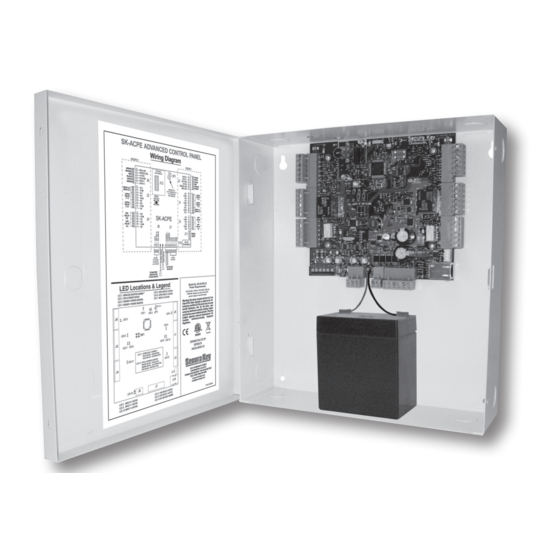
InStAllAtIon & oPerAtIng MAnuAl WIRING The SK-ACPE unit is organized so that the wiring for door #1 is on the right side of the panel and the wiring for door #2 is on the left side of the panel (see figure 3). -
Page 9: Power And Batteries
SK-ACPE. When 16.5 – 24 volts is used to power the SK-ACPE, you may connect the red and black wires to a 12 volt standby battery. Polarity (+/-) must be observed. The, 10” X 11” SK-ACPE-LE can accommodate batteries up to 4.0 Amp-hours... -
Page 10: Outputs
InStAllAtIon & oPerAtIng MAnuAl OUTPUTS Each door controlled by the SK-ACPE has two double pole, double throw relays associated with it. The “latch relays” are located on “J1” and “J2”, terminals 1-6. The “auxiliary relays” are located on “J3” and “J4”. One pole of the latch relay is typically used to open or close a circuit to unlock a door or activate a gate operator. -
Page 11: Typical Door Installation Diagram/Cable Types
SK-ACPe InStAllAtIon & oPerAtIng MAnuAl TYPiCAL DOOr iNSTALLATiON INPUT 2-1 INPUT 1-2 INPUT 2-2 READER 2ND DOOR INPUT 1-1 INPUT 2 DOOR MONITOR RELAY 2-1 REMOTE READER DOOR- INPUT 1 COMMUNICATIONS OPEN TO MODEM, PC, SWITCH SERIAL PRINTER. TO RS-485... -
Page 12: Rs-232 Connections
5-conductor cable. SUGGESTED CABLE IS Belden 9535. RS-232 is used to connect the COM port of a PC to a single SK-ACPE, or as a gateway to a network of SK-ACPEs. (COM ports are typically DB9 male or DB25 male jacks on the back of a personal computer.) Newer computers may not have COM ports, in which... - Page 13 SK-ACPe InStAllAtIon & oPerAtIng MAnuAl installation of Metal Oxide Varistor with electric Strike N.O. LOCK ACCeSS POWer CONTrOL SuPPLY uNiT AC or DC N.C. iNSTALL MOV Here STriKe Install the enclosed 40-volt MOV (Metal Oxide Varistor) across the relay contacts in the access control unit, as shown.
-
Page 14: Rs-485 Connections
Where the distance from the PC to any one of the SK-ACPE units is greater than 100’, you may install an RS-232 to RS-485 converter (Secura Key p/n NET-CONV-P) to the COM port of the computer. If your PC does not have a COM port you will need to purchase a USB-to-serial converter (SK-USB), and then connect the RS-485 converter to the USB converter. -
Page 15: Factory Settings
SK-ACPe InStAllAtIon & oPerAtIng MAnuAl FACTORY SETTINGS When shipped from the factory, the SK-ACPE has the following settings: Facility Code None* All Cards Time Zone 0 (void) No Limited Use Cards Settings Latch timer = 1 Second APB Timer = 0 Minutes (off) -
Page 16: Readers And Cards
Facility Codes and the same ID Number. For example, if you have a card with Facility Code A1 and ID Number 15 and you have a card with Facility Code B2 and ID Number 15, and the SK-ACPE has been programmed to accept both Facility Codes, it will see these as the same card. -
Page 17: Appendix A - Wiring And System Configurations
SERIAL PRINTER 500 feet. SK-USB may be required if your PC does not MONITORS ALL SYSTEM have a COM port. ACTIVITY* NOTe: Each SK-ACPE above can support 2 Wiegand output card readers. * See Appendix D for printer configuration. Figure A-1... - Page 18 Note: When using the RS-232 to RS-485 converter, you cannot use the stubbed, star fanout or “T” configuration. All network connections from SK-ACPE to the next SK-ACPE must be in parallel with each other. The J8 connector, Pins 1 and 2 must be a twisted pair. Pin 3 (Ground) is not connected * See Appendix D for printer configuration.
- Page 19 SK-ACPE to reader. Total cable SERIAL PRINTER length 500 feet. MONITORS ALL SYSTEM eTHerNeT CABLe: ACTIVITY* Standard Ethernet cable connector connected to existing LAN. NOTe: Each SK-ACPE above can support 2 Wiegand output card readers. * See Appendix D for printer configuration. Figure A-3...
- Page 20 For Bench Testing or field connection with a laptop rK-WM or rK-WS or rK-Wl SK-MDM — Modem - 56K Baud External Modem for Proximity Readers (2 per SK-ACPE) dial-up connection to any SK-ACPE with MLD software rKCM-02 Molded Proximity Cards SK-Plug9 — Computer connector (DB9) with wire pigtail. Specify Quantity or RKKT-02 Key Tags SK-ACPe-PS —...
-
Page 21: Specifications
SK-ACPe InStAllAtIon & oPerAtIng MAnuAl SPECIFICATIONS SK-ACPE-LE PHYSICAL Depth 3.0” (7.62 cm) Width 10.0” (25.40 cm) Height 11.0” (27.94 cm) Weight 68.8 oz. (1.95 kg) Housing Material is All Steel; Color is Beige POWER REQUIREMENTS 16.5-24VAC (50-60 HZ), 40 VA or 16-30 VDC, 500 mA If RK-WL readers are used, recommend a 16.5-24 VAC 40 VA transformer. -
Page 22: Appendix C - Connecting A Modem To Sk-Acpe
APPENDIX C CONNECTING A MODEM TO SK-ACPE The SK-MDM (U.S. Robotics) has been preconfigured to work with Secura Key access control systems and SK-NET-MLD software. (NOTE: SK-NET-DM and the free download version of SK-NET™ do not support modem connections.) NOTE: This modem requires version 3.0 or later of SK-NET-MLD software. -
Page 23: Appendix D - Connecting An Sk-Acpe To A Local Area Network
Alternately, you can use either the SK-WLSE-MOD Wireless Network Module (which connects with an 802.11 wireless network.) This unit plugs into connector J12 on the SK-ACPE, and it receives its power from the panel. You must move the 2-pin jumper at J1 to pins 1 and 2 before installing the module. - Page 24 InStAllAtIon & oPerAtIng MAnuAl Hardware Connection You must connect a Windows computer COM port to the J11 port on each SK-ACPE, using the RS-232E cable (or to J7 using a wire pigtail, see Figure 3). If your computer does not have a serial COM port, purchase and install the SK-USB USB-to-Serial Converter on your computer, and connect the DB9M connector on the converter to the DB9F connector on the RS-232E cable.
- Page 25 CONFIGURING THE SK-ACPE FOR A SERIAL PRINTER A Serial Printer can be connected to any SK-ACPE in the system to monitor (print) all system trans- actions. The SK-ACPE must be configured for this function, using a terminal program, such as SK-NET Terminal or HyperTerminal.
- Page 26 HyperTerminal is available free in Windows XP, but not in later Windows versions. Visit www.hilgreave.com to purchase HyperTerminal for use in Windows Vista, 7 or 8. Follow this procedure to configure HyperTerminal for the SK-ACPE TCP/IP setup: 1. Connect your computer to the SK-ACPE being configured, 2.
-
Page 27: Appendix E - Sk-Acpe Troubleshooting Guide
SK-ACPe InStAllAtIon & oPerAtIng MAnuAl APPENDIX E SK-ACPE TROUBLESHOOTING GUIDE Cards do not work when creating a new Access Group 1. Did you drag-and-drop readers into the new Access Group? a. From the Explorer screen, click on All Readers. b. Drag-and-drop readers from the right side of the screen into the new Access Group. - Page 28 “Invalid Facility Code” message when using newly-added cards 1. Do the new cards have a different Facility Code than the previous ones? a. Go to one of the SK-ACPE panels. Take a sample card with each different facility code. Press the reset button.
- Page 29 If the Wizard finds the connection, click OK and then Connect. If not, select your connection below. 1. RS-232 direct connect, computer COM port to the SK-ACPE COM port. (See Section 1.6.) 2. RS-232 to RS-485 converter, computer to converter to the SK-ACPE.
- Page 30 If these voltages are incorrect, contact Secura Key Technical Support. 1.8 Power Reset Occasionally it may become necessary to perform a power reset on a SK-ACPE panel (for example, after a power surge.) The SK-ACPE has a multi-level power reset procedure, with options depending on how long you hold down the reset button following restoration of power.
- Page 31 Replacing an SK-ACPE When replacing or adding an SK-ACPE to a system, it is recommended to perform a “2-beep” power reset (See Sec. 1.8). NOTE: There are no changes required in SK-NET™ when replacing a card reader connected...
-
Page 32: Appendix F - Preventing Lightning Damage
• On the AC line voltage input to the PC. (A UPS with surge protection is recommended). • On the AC line voltage input to any transformer or DC Power Supply connected to an SK-ACPE or Modem. • On RS-485 data lines connecting an SK-ACPE to a PC, or to other SK-ACPE’s. - Page 33 Leave the cable shield unconnected at the opposite end. MORE INFORMATION For more information on lightning, including additional lightning protection methods and a US lightning density map, see Secura Key Applications Bulletin #28 on our website. (www.securakey.com)
- Page 34 The DTK-CR is a multi-line surge suppressor that can protect card readers and keypads from damaging power surges. It can be used between an SK-ACPE panel and any wiegand-output reader/keypad. This is especially useful where readers are located on gates and parking control equipment.
- Page 35 STRIKE CONNECTING THE DTK-XR (DATA LINE PROTECTION) The DTK-XR is a multi-line surge suppressor that can protect an SK-ACPE control panel, or other access control unit from damaging power surges. Locate the DTK-XR at least three (3) wire-feet away from the unit to be protected.
- Page 36 SK-ACPe InStAllAtIon & oPerAtIng MAnuAl If the access control unit is connected to other units via RS-485 you may connect the “A” and “B” lines of the RS-485 twisted pair to 6V IN and 6V OUT. If you are using a dial-up modem, you may protect the modem by running the “Tip” (usually green) and “Ring”...
-
Page 37: Appendix G -What's New, And What Has Not Changed In The Sk-Acpe
The jumper that changes input circuits from NC to NO has been removed. On the SK-ACPE, this setting is now changed in the SK-NET software (Version 5.1 is required). If you do not have Version 5, the inputs will default to NC. - Page 38 SK-ACPe InStAllAtIon & oPerAtIng MAnuAl The Reset Button has been moved – it is next to connector J2. AC Power is now recommended, due to a redesigned power supply. A 16.5VAC 40VA transformer such as SK-XFRMR can be used to power the board. 24VDC power is also recommended, using a DC supply such as SK-DCPWR.
- Page 39 SK-ACPe InStAllAtIon & oPerAtIng MAnuAl WARRANTY For warranty terms and conditions, please refer to the Secura Key Website (www.securakey.com) the current Secura Key price list, or contact the Factory. WARNING: INSTRUCTION TO THE USER This equipment has been tested and found to comply with the limits for a class B digital device, pursuant to part 15 of the FCC Rules.
- Page 40 www.SecuraKeyStore.com (800) 878-7829 sales@securakeystore.com...