Cisco ASR 9001 Hardware Installation Manual
Hide thumbs
Also See for ASR 9001:
- Hardware installation manual (114 pages) ,
- Installation manual (24 pages) ,
- Overview and reference manual (170 pages)
Table of Contents
Advertisement
Advertisement
Table of Contents
Troubleshooting

Related Manuals for Cisco ASR 9001


Summary of Contents for Cisco ASR 9001
- Page 1 Cisco ASR 9001 and Cisco ASR 9001-S Routers Hardware Installation Guide First Published: 2013-08-25 Last Modified: 2016-10-04 Americas Headquarters Cisco Systems, Inc. 170 West Tasman Drive San Jose, CA 95134-1706 http://www.cisco.com Tel: 408 526-4000 800 553-NETS (6387) Fax: 408 527-0883...
- Page 2 Cisco and the Cisco logo are trademarks or registered trademarks of Cisco and/or its affiliates in the U.S. and other countries. To view a list of Cisco trademarks, go to this URL: www.cisco.com/go/trademarks . Third-party trademarks mentioned are the property of their respective owners. The use of the word partner does not imply a partnership relationship between Cisco and any other company.
-
Page 3: Table Of Contents
Rack-Mounting and Air Flow Clearance Guidelines Telco 2-Post Rack Open 4-Post Rack Enclosed Rack with Perforated Sides Air Flow Guidelines for Enclosed Rack Installation Temperature and Humidity Guidelines Power Connection Guidelines Cisco ASR 9001 and Cisco ASR 9001-S Routers Hardware Installation Guide... - Page 4 Installing the Air Plenum Kit in an ETSI Two-Post to Four-Post Rack Installing Modules and Cables in the Chassis C H A P T E R 3 Fixed 4x10-Gigabit Ethernet Ports Cisco ASR 9001 and Cisco ASR 9001-S Routers Hardware Installation Guide...
- Page 5 Connecting Power to the Router Connecting Power to an AC-Powered Router Connecting Power to a DC-Powered Router Powering on the Router Troubleshooting the Installation C H A P T E R 4 Cisco ASR 9001 and Cisco ASR 9001-S Routers Hardware Installation Guide...
- Page 6 Troubleshooting the Cooling Subsystem Fan Tray Operation Power Module Fans Over-temperature Conditions Isolating Cooling Subsystem Problems Replacing Cisco ASR 9001 Router Components C H A P T E R 5 Cisco ASR 9001 and Cisco ASR 9001-S Routers Hardware Installation Guide...
- Page 7 SFP+ Transceiver Modules DWDM SFP+ Transceiver Modules DWDM XFP Transceiver Modules CWDM SFP Transceiver Modules 10GBASE CWDM SFP+ 40km Transceiver Modules DWDM SFP Transceiver Modules DWDM SFP+ Transceiver Modules Cisco ASR 9001 and Cisco ASR 9001-S Routers Hardware Installation Guide...
- Page 8 Contents 10-Gigabit Ethernet XFP and 40-Gigabit QSFP Modules DWDM XFP Transceiver Modules Site Log A P P E N D I X B Site Log Cisco ASR 9001 and Cisco ASR 9001-S Routers Hardware Installation Guide viii...
- Page 9 Preface This Cisco ASR 9001 and Cisco ASR 9001-S Routers Hardware Installation Guide preface contains these sections: • Changes to This Document, page ix • Audience, page x • Purpose, page x • Document Organization, page x • Documentation Conventions, page xi •...
-
Page 10: Document Organization
Initial release of this document. Audience This guide is written for hardware installers and system administrators of Cisco routers. These users must have a substantial background in installing and configuring router and switch-based hardware. Also, they should be familiar with electronic circuitry and wiring practices, and have experience as an electronic or electromechanical technician. -
Page 11: Documentation Conventions
Default responses to system prompts are in square brackets. !, # An exclamation point (!) or a pound sign (#) at the beginning of a line of code indicates a comment line. Cisco ASR 9001 and Cisco ASR 9001-S Routers Hardware Installation Guide... -
Page 12: Obtaining Documentation And Submitting A Service Request
Subscribe to What's New in Cisco Product Documentation, which lists all new and revised Cisco technical documentation as an RSS feed and delivers content directly to your desktop using a reader application. The RSS feeds are a free service. -
Page 13: Preparing For Installation
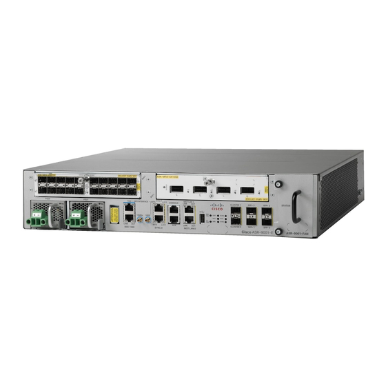
Cisco ASR 9001-S Router The Cisco ASR 9001-S Router is a 60 Gbps variant of the Cisco ASR 9001 Router. Similar to other routers in the Cisco ASR 9000 Series, running Cisco IOS XR software images, the Cisco ASR 9001-S Router delivers the features and services found on the ASR 9000 Series platforms, allowing customers to standardize on the same Cisco IOS XR image. -
Page 14: Safety Guidelines
Figure 2: Front Panel of the Cisco ASR 9001-S Router In order to achieve the full bandwidth of 120 Gbps and to enable the disabled ports, a Cisco license can be obtained. Once the license is obtained and installed, the Cisco ASR 9001-S Router must be reloaded to bring up the full 120 Gbps capacity. -
Page 15: General Safety Guidelines
Commission (IEC) 364, part 1 through part 7. Compliance and Safety Information Both the Cisco ASR 9001 Router and the Cisco ASR 9001-S Router are designed to meet the regulatory compliance and safety approval requirements. See the Regulatory Compliance and Safety Information for Cisco ASR9000 Series Routers. -
Page 16: Energy Hazard
Preparing for Installation Energy Hazard Energy Hazard The Cisco ASR 9001 Router can be configured for a DC power source. Do not touch terminals while they are live. Observe this warning to prevent injury. Warning Hazardous voltage or energy may be present on power terminals. Always replace cover when terminals are not in service. -
Page 17: Lifting Guidelines
• To mount the router between two posts or rails, the usable aperture (the width between the inner edges of the two mounting flanges) must be at least 17.75 inches (45.09 cm) for the Cisco ASR 9001 Router. Cisco ASR 9001 and Cisco ASR 9001-S Routers Hardware Installation Guide... -
Page 18: Cisco Asr 9001 And Cisco Asr 9001-S Routers Hardware Installation Guide
Preparing for Installation Site Layout and Equipment Dimensions • Height of the Cisco ASR 9001 Router is 3.47 inches (8.8 cm). • When fully populated with cards, the router can weigh as much as 37.91 pounds (17.2 kg). To maintain equipment rack stability and to ensure your safety, the rack is provided with stabilizing devices. -
Page 19: Site Wiring Guidelines
Preparing for Installation Site Wiring Guidelines The following figure shows the top-down view chassis dimensions of the Cisco ASR 9001 Router. Figure 4: Cisco ASR 9001 Router Chassis Footprint and Dimensions — Top View Site Wiring Guidelines When planning the location of the router, consider distance limitations for signaling, electromagnetic interference (EMI), and connector compatibility. -
Page 20: Chassis Air Flow Guidelines
Chassis Air Flow Guidelines Cool air is circulated through the Cisco ASR 9001 Router by one fan tray located along the right side of the router (see the following figure). -
Page 21: Rack-Mounting And Air Flow Clearance Guidelines
Note 4-post rack. Figure 5: Air Flow Path through the Cisco ASR 9001 Router When selecting a site to install the router, observe these guidelines: • Dust free area—Site should be as dust free as possible. Dusty environments can clog the power supply intake vents, reducing the cooling air flow through the router. -
Page 22: Telco 2-Post Rack
In the front-mounted position, you secure the chassis rack-mounting brackets directly to the rack posts (see the following figure as an example of a Cisco ASR 9001 Router rack mounting). Two rear mounting brackets are provided for mounting the Cisco ASR 9001 Router in a 2-post rack. -
Page 23: Open 4-Post Rack
Preparing for Installation Rack-Mounting and Air Flow Clearance Guidelines The mounting brackets on the Cisco ASR 9001 Router chassis have a pair of holes at the top and bottom Note of each bracket and three slots (elongated holes). If the Cisco ASR 9001 Router is to be mounted in a 2-post 19-inch rack, you must first use the holes to locate and position the brackets on the rack. -
Page 24: Enclosed Rack With Perforated Sides
Air Flow Guidelines for Enclosed Rack Installation To install a Cisco ASR 9001 Router in a 4-post enclosed cabinet, the front and rear doors of the cabinet must be removed or be perforated with a minimum of 65% open area (70% for ETSI 800mm racks). -
Page 25: Temperature And Humidity Guidelines
Preparing for Installation Temperature and Humidity Guidelines The following figure shows the side and rear chassis air flow clearance requirements for mounting the Cisco ASR 9001 Router in a 4-post enclosed rack. Figure 8: ASR 9001 Clearance Requirements for an Enclosed 4-Post Rack Installation... -
Page 26: Ac Powered Routers
Preparing for Installation Power Connection Guidelines Each Cisco ASR 9001 Router is powered by only one type of input: AC or DC. A hybrid (AC+DC) power Caution configuration is not supported. Proper grounding is necessary to avoid damage from lightning and power surges. See... - Page 27 8.2 feet (2.5 m) 10 A, 250 V Figure 18: AC Power Cord CAB-9K10A-EU Israel SFS-250V-10A-IS 8.2 feet (2.5 m) 10 A, 250 V Figure 19: AC Power Cord SFS-250V-10A-IS Cisco ASR 9001 and Cisco ASR 9001-S Routers Hardware Installation Guide...
-
Page 28: Ac Power Cord Illustrations
Figure 9: AC Power Cord CAB-AC Figure 10: AC Power Cord CAB-L620P-C13-JPN Figure 11: AC Power Cord CAB-ACA Figure 12: AC Power Cord CAB-ACI Cisco ASR 9001 and Cisco ASR 9001-S Routers Hardware Installation Guide... - Page 29 Preparing for Installation Power Connection Guidelines Figure 13: AC Power Cord CAB-ACR Figure 14: AC Power Cord CAB-ACS Figure 15: AC Power Cord CAB-ACU Cisco ASR 9001 and Cisco ASR 9001-S Routers Hardware Installation Guide...
- Page 30 Preparing for Installation Power Connection Guidelines Figure 16: AC Power Cord CAB-ACC Figure 17: AC Power Cord CAB-ACSA Figure 18: AC Power Cord CAB-9K10A-EU Cisco ASR 9001 and Cisco ASR 9001-S Routers Hardware Installation Guide...
-
Page 31: Dc Powered Router
The length of the cables depends on your router location from the source power. Note DC power cables are not available from Cisco, but they are available from external commercial cable vendors. You must terminate DC power cables using terminal blocks. The terminal blocks are supplied along with the DC power supply modules from Cisco. - Page 32 Hazardous voltage or energy may be present on power terminals. Always replace cover when terminals are not in service. Be sure uninsulated conductors are not accessible when cover is in place. Statement 1086 Cisco ASR 9001 and Cisco ASR 9001-S Routers Hardware Installation Guide...
- Page 33 DC cable leads . Be sure that the positive (+) and negative (–) cable leads match the positive (+) and negative (–) labels on the power module when making the measurement. • Green (or green and yellow) cable typically indicates that it is a ground cable. Cisco ASR 9001 and Cisco ASR 9001-S Routers Hardware Installation Guide...
-
Page 34: Nebs Supplemental Unit Bonding And Grounding Guidelines
(NEBS) requirements as well as safety compliance requirements. These grounding points are referred to as the NEBS bonding and grounding points. The following figure shows the NEBS grounding locations for the Cisco ASR 9001 Router. These bonding and grounding connections satisfy the Telcordia NEBS requirements for supplemental Note bonding and grounding connections. -
Page 35: Cisco Asr 9001 Router Port Connection Guidelines
Ports labeled Ethernet, SYNC, CONSOLE, and AUX are safety extra-low voltage (SELV) circuits. SELV Caution circuits should only be connected to other SELV circuits. In Cisco ASR 9001-S Router, two 10 GE fixed SFP+ ports (SFP+2 and SFP+3) are disabled by default, Note and can be enabled by a license upgrade. - Page 36 CONSOLE and AUX Fixed SFP+ ports ports Management LAN ports The following table lists the Cisco ASR 9001 Router front panel ports description. Table 3: Cisco ASR 9001 Router Front Panel Ports Description Port Name Connector Type Description TOD Port...
-
Page 37: Console Port And Auxiliary Port Connection Guidelines
Plugs. Console Port and Auxiliary Port Connection Guidelines The RP has two EIA/TIA-232 (formerly RS232) serial RJ-45 connection ports (See Cisco ASR 9001 Router Front Panel Ports figure): • Console port—RJ-45 interface for connecting a data terminal device to the router, which you need to perform the initial configuration of the router. -
Page 38: Console Port Signals
(DCE) device (such as another router) to the RP. The AUX port supports hardware flow control and modem control. The following table lists the signals used on the Auxiliary port. Cisco ASR 9001 and Cisco ASR 9001-S Routers Hardware Installation Guide... -
Page 39: Management Lan Ports Connection Guidelines
The following table lists the signals used on the Management LAN ports. Table 6: RP Management LAN Port Signals MGT LAN Port Pin 10Base-T, 100Base-TX Signal 1000Base-T Signal Transmit+ BI_DA+ Transmit– BI_DA– Cisco ASR 9001 and Cisco ASR 9001-S Routers Hardware Installation Guide... -
Page 40: Management Lan Port Led Indicators
Figure 24: RP Management LAN Port LED Indicators Management LAN RJ-45 Cabling When connecting the RJ-45 port to a hub, repeater, or switch, use the straight-through cable pinout shown in the following figure. Cisco ASR 9001 and Cisco ASR 9001-S Routers Hardware Installation Guide... -
Page 41: Sync Ports Connection Guidelines
The BITS input can be T1, E1 or 64K 4/. The BITS output can be T1, E1 or 6.312M 5/. When configured as J.211 ports, they can be used as Universal Timing Interface (UTI) ports to synchronize timing across multiple routers by connecting to an external timing source. Cisco ASR 9001 and Cisco ASR 9001-S Routers Hardware Installation Guide... -
Page 42: Sync Port Led Indicators
Table 7: BITS/J.211 Connector Pinout Signal Note DTI_P/BITS_RX_P Bi-direction for DTI, T1/E1/64K Input DTI_P/BITS_RX_N Bi-direction for DTI, T1/E1/64K Input — — BITS_TX_P* T1/E1/6.321M Output BITS_TX_N* T1/E1/6.321M Output — — — — Cisco ASR 9001 and Cisco ASR 9001-S Routers Hardware Installation Guide... -
Page 43: Rp External Usb Port
RP External USB Port The Cisco ASR 9001 Router RP card has an external USB Type A slot accessible on the front panel. The front panel USB slot accepts widely available USB thumb drives. The only restriction on devices you can plug into the front panel external USB slot is that they need to be USB 2.0 devices. - Page 44 Preparing for Installation RP External USB Port Cisco ASR 9001 and Cisco ASR 9001-S Routers Hardware Installation Guide...
-
Page 45: Unpacking And Installing The Chassis
Note chassis weighs 24.69 pounds (11.2 kg). The chassis is designed to be lifted by two persons. The Cisco ASR 9001 Router is not designed to be installed as a shelf-mounted or a free-standing router. Caution The router must be installed in a rack that is secured to the building structure. You must install the router in either a telco-style frame or a four-post equipment rack. -
Page 46: Unpacking The Cisco Asr 9001 Router
Unpacking and Installing the Chassis Unpacking the Cisco ASR 9001 Router Unpacking the Cisco ASR 9001 Router Follow these steps to unpack the Cisco ASR 9001 Router from its shipping container (see the below figure). Procedure Step 1 Cut the packaging tape and open the cardboard shipping container. - Page 47 Unpacking and Installing the Chassis Unpacking the Cisco ASR 9001 Router What to Do Next Figure 28: Unpacking the Cisco ASR 9001 Router from the Shipping Container Cardboard packaging Cardboard cap container Accessory tray Foam packaging material - bottom cap...
-
Page 48: Positioning The Router
Use a safety hand truck to move the router to the location where the router is being installed in a rack. Installing the Cisco ASR 9001 Chassis This chapter describes how to install a Cisco ASR 9001 chassis in a rack. It includes the following sections: Before you Begin Before you install the chassis, make sure that you have following tools and equipment: •... -
Page 49: Verifying Rack Dimensions
(two screws per bracket) on each side. To install the chassis in a two-post rack, follow these steps: Cisco ASR 9001 and Cisco ASR 9001-S Routers Hardware Installation Guide... - Page 50 Installing the Chassis in a Two-Post Rack Procedure Step 1 Attach the mounting flanges to the chassis by using the Cisco-supplied screws. To accommodate racks with different hole patterns in their mounting flanges, the chassis rack-mounting flanges have three oblong screw holes on each side.
-
Page 51: Installing The Chassis In A Four-Post Rack
Unpacking and Installing the Chassis Installing the Chassis in a Four-Post Rack What to Do Next Figure 31: Installing the Cisco ASR 9001 Chassis in a Two-Post Rack Three screws on each side (minimum two) to attach the chassis to the rack... - Page 52 Step 3 Fully tighten both screws to the chassis on each side to secure the chassis to the rear posts. Cisco ASR 9001 and Cisco ASR 9001-S Routers Hardware Installation Guide...
- Page 53 Unpacking and Installing the Chassis Installing the Chassis in a Four-Post Rack What to Do Next Figure 32: Installing the Cisco ASR 9001 Router Chassis in a Four-Post Rack Three screws on each side Two rear mounting (minimum two) to attach brackets on each side to the chassis to the rack.
-
Page 54: Supplemental Bonding And Grounding Connections
Tighten the grounding screws securely to the receptacles. Step 3 Prepare the other end of the grounding wire, and connect it to the appropriate grounding point at your site to ensure an adequate earth ground. Cisco ASR 9001 and Cisco ASR 9001-S Routers Hardware Installation Guide... -
Page 55: Installing The Optional Air Plenum Kit
Figure 33: NEBS Bonding and Grounding for the Cisco ASR 9001 Router Installing the Optional Air Plenum Kit The Cisco ASR 9001 Router has an optional air plenum kit (PID ASR-9001-PLENUM=) that converts the chassis from side-to-side ventilation to front-to-back ventilation. This section describes how to install the air plenum kit in a rack. -
Page 56: Supported Rack Types And Adapter Plates
Installing the Air Plenum Kit The air plenum kit is mounted in the rack before the Cisco ASR 9001 Router is installed. The steps for mounting the air plenum kit in the rack are different, depending on the whether the kit is pre-assembled before mounting it in the rack or assembled after the plenum base is mounted in the rack. -
Page 57: Installing The Air Plenum Kit In A 19-Inch Rack
The cable guide is attached to the rack after the Cisco ASR 9001 Router is installed. Installing the Air Plenum Kit in a 19-inch Rack The air plenum kit is assembled and mounted in the rack before the Cisco ASR 9001 Router is installed. Note... - Page 58 If the front to rear spacing for the cabinet is 18.4 inches, attach the rear adapter plates for additional support (see Step 7). Figure 34: Installing the Plenum Base in a 19-inch Rack Cisco ASR 9001 and Cisco ASR 9001-S Routers Hardware Installation Guide...
- Page 59 Step 4 Attach the left and right air baffles to the plenum base using the Cisco supplied M5x10mm screws (four for each air baffle). The keyholes on each side of the plenum base will help to guide the air baffles into position (see Attaching the Air Baffles to the Plenum Base figure).
- Page 60 Figure 35: Attaching the Rear Adapter Plates (Four-Post Rack) Step 8 Place the Cisco ASR 9001 Router on a flat and stable surface. Attach the rear grounding bracket (see the figure below). Cisco ASR 9001 and Cisco ASR 9001-S Routers Hardware Installation Guide...
- Page 61 Unpacking and Installing the Chassis Installing the Air Plenum Kit Figure 36: Rear Grounding Bracket Cisco ASR 9001 and Cisco ASR 9001-S Routers Hardware Installation Guide...
- Page 62 Unpacking and Installing the Chassis Installing the Air Plenum Kit Step 9 Install the Cisco ASR 9001 Router in the plenum assembly in the rack (see Installing the Chassis in a Two-Post Rack, on page 37 Installing the Chassis in a Four-Post Rack, on page 39).
-
Page 63: Installing The Air Plenum Kit In An Etsi Two-Post To Four-Post Rack
Installing the Air Plenum Kit in an ETSI Two-Post to Four-Post Rack Note The air plenum kit is assembled and mounted in the rack before the Cisco ASR 9001 Router is installed. To install the air plenum kit in an ETSI four-post open rack, follow these steps:... - Page 64 Unpacking and Installing the Chassis Installing the Air Plenum Kit Figure 38: Attaching the Air Baffles to the Plenum Base Air Baffle Plenum base Cisco ASR 9001 and Cisco ASR 9001-S Routers Hardware Installation Guide...
- Page 65 Position the cable management tray at the front of the plenum assembly (the figure below). Insert and hand-tighten both captive screws (one on each side) to secure the cable management tray to the plenum assembly. Cisco ASR 9001 and Cisco ASR 9001-S Routers Hardware Installation Guide...
- Page 66 Lift the plenum assembly to the desired position in the rack. Align the screw holes on the adapter plates of the plenum assembly with the mounting holes in the rack. Cisco ASR 9001 and Cisco ASR 9001-S Routers Hardware Installation Guide...
- Page 67 Attach the rear adapter plates to the rear side of the plenum assembly. Fasten the rear adapter plates with M3 x 10mm screws, three on each side (see the figure below). Cisco ASR 9001 and Cisco ASR 9001-S Routers Hardware Installation Guide...
- Page 68 Note Figure 42: Attaching the Rear Adapter Plates Step 8 Place the Cisco ASR 9001 Router on a flat and stable surface. Attach the rear grounding bracket (Rear Grounding Bracket figure). Step 9 Install the Cisco ASR 9001 Router in the plenum assembly in the rack (see...
-
Page 69: Installing Modules And Cables In The Chassis
Each fixed SFP+ port has an adjacent Link LED visible on the front panel. The Link LED indicates the status of the associated SFP+ port. In Cisco ASR 9001-S Router, two 10 GE fixed SFP+ ports (SFP+2 and SFP+3) are disabled by default, Note and can be enabled by a license upgrade. -
Page 70: Modular Port Adapters
2-Port 40 Gigabit Ethernet Modular Port Adapter, on page 63 • 1-Port 40 Gigabit Ethernet Modular Port Adapter, on page 65 In the Cisco ASR 9001-S Router, one bay (MPA1) is disabled by default, and can be enabled by a license Note upgrade. -
Page 71: 20-Port Gigabit Ethernet Modular Port Adapter
Port is enabled and the link is up. The MPA A/L LED will blink green when there is traffic activity. Amber Port is enabled and the link is down. Cisco ASR 9001 and Cisco ASR 9001-S Routers Hardware Installation Guide... -
Page 72: 4-Port 10 Gigabit Ethernet Modular Port Adapter
Status LEDs, on page 99 section. The following figure shows an example of the 4-Port 10 Gigabit Ethernet modular port adapter. Figure 45: 4-Port 10 Gigabit Ethernet Modular Port Adapter Cisco ASR 9001 and Cisco ASR 9001-S Routers Hardware Installation Guide... -
Page 73: 2-Port 10 Gigabit Ethernet Modular Port Adapter
Each XFP cage on the 2-Port 10 Gigabit Ethernet modular port adapter has an adjacent Link LED visible on the front panel. The Link LED indicates the status of the associated XFP port, as described in Status LEDs, on page 99 section. Cisco ASR 9001 and Cisco ASR 9001-S Routers Hardware Installation Guide... - Page 74 Amber Port is enabled and the link is down. STATUS Modular port adapter power is off. Green Modular port adapter is ready and operational. Cisco ASR 9001 and Cisco ASR 9001-S Routers Hardware Installation Guide...
-
Page 75: 2-Port 40 Gigabit Ethernet Modular Port Adapter
Each QSFP cage on the 2-Port 40 Gigabit Ethernet modular port adapter has an adjacent Link LED visible on the front panel. The Link LED indicates the status of the associated QSFP port, as described in Table 4-4 Cisco ASR 9001 and Cisco ASR 9001-S Routers Hardware Installation Guide... - Page 76 The following table describes the 2-Port 40 Gigabit Ethernet modular port adapter LEDs. Table 12: 2-Port 40 Gigabit Ethernet Modular Port Adapter LEDs LED Label Color State Meaning Port is not enabled. Green Port is enabled and the link is up. Cisco ASR 9001 and Cisco ASR 9001-S Routers Hardware Installation Guide...
-
Page 77: 1-Port 40 Gigabit Ethernet Modular Port Adapter
The QSFP cage on the 1-Port 40 Gigabit Ethernet modular port adapter has an adjacent Link LED visible on the front panel. The Link LED indicates the status of the associated QSFP port, as described in Status LEDs, on page 99 section. Cisco ASR 9001 and Cisco ASR 9001-S Routers Hardware Installation Guide... - Page 78 The following table describes the 1-Port 40 Gigabit Ethernet modular port adapter LEDs. Table 13: 1-Port 40 Gigabit Ethernet Modular Port Adapter LEDs LED Label Color State Meaning Port is not enabled. Green Port is enabled and the link is up. Cisco ASR 9001 and Cisco ASR 9001-S Routers Hardware Installation Guide...
-
Page 79: Installing And Removing Modular Port Adapters
Installing and Removing Modular Port Adapters These sections describe how to install or remove modular port adapters (MPAs) on the Cisco ASR 9001 Router. Handling Modular Port Adapters (MPAs) Each modular port adapter (MPA) circuit board is mounted on a metal carrier, and is sensitive to electrostatic discharge (ESD) damage. -
Page 80: Online Insertion And Removal
Figure 49: Handling a Modular Port Adapter (MPA) Online Insertion and Removal Cisco ASR 9001 Router modular port adapters (MPAs) support online insertion and removal (OIR). Modular port adapters (MPAs) support three types of OIR: • Soft OIR Soft OIR uses the IOS XR hw-module subslot 0/0/1 reload, hw-module subslot 0/0/1 shutdown, and no hw-module subslot 0/0/1 shutdown commands to complete online insertion and removal. -
Page 81: Modular Port Adapter (Mpa) Installation And Removal
Installing Modules and Cables in the Chassis Modular Port Adapter (MPA) Installation and Removal If the bay is empty when the Cisco ASR 9001 Router modular line card (MLC) boots you can do the following: • ◦ Insert a 20 GE MPA ◦... -
Page 82: Cleaning Optical Devices
If the modular port adapters (MPAs) do not become active within three minutes, refer to the system console messages. If there is no indication that a field-programmable device (FPD) upgrade is underway, see Troubleshooting the Installation, on page 85 section. Cisco ASR 9001 and Cisco ASR 9001-S Routers Hardware Installation Guide... -
Page 83: Using Show Commands To Verify Modular Port Adapter (Mpa) Status
Modular port adapter (MPA) type in that slot, number of ports, hardware revision, part number, and EEPROM contents. show hw-module fpd location <rack/slot/subslot> FPD version information of modular port adapters (MPAs) in the system. Cisco ASR 9001 and Cisco ASR 9001-S Routers Hardware Installation Guide... -
Page 84: Using The Ping Command To Verify Network Connectivity
Cisco ASR 9000 Series Router and the Cisco ASR 9000 A9K-MOD80G-H. The ping command sends an echo request out to a remote device at an IP address that you specify. After sending a series of signals, the command waits a specified time for the remote device to echo the signals. -
Page 85: Installing And Removing Sfp And Xfp Modules
• A cable-management bracket Cable Management Tray A cable-management tray is mounted at the bottom of the Cisco ASR 9001 Router chassis for routing interface cables to the RP. The following figure shows a typical cable routing through the cable-management tray. -
Page 86: Installing A Cable Management Tray
Connect all the cables to the intended ports and pass them through the cable management tray in an organized manner. Removing a Cable-Management Tray To remove a cable-management tray, follow these steps: Cisco ASR 9001 and Cisco ASR 9001-S Routers Hardware Installation Guide... -
Page 87: Cable Management Bracket
Cable Management Bracket The Cisco ASR 9001 Router provides a cable management bracket at the middle of the router chassis. The following figure shows a typical cable routing for the Cisco ASR 9001 Router. Figure 52: Example Cable Routing through Cisco ASR 9001 Router Cable Management Brackets When shipped, the cable-management bracket is not attached to the router chassis. -
Page 88: Installing A Cable Management Bracket
Connect all the cables to the intended ports and pass them through the cable management bracket in an organized manner. Removing a Cable-Management Bracket To remove a cable-management bracket, follow these steps: Cisco ASR 9001 and Cisco ASR 9001-S Routers Hardware Installation Guide... -
Page 89: Connecting Route Processor Cables
This section describes how to connect cables to the console, auxiliary, and Ethernet ports on the RP. The console and auxiliary ports are both asynchronous serial ports; any devices connected to these ports must be capable of asynchronous transmission. Most modems are asynchronous devices. Cisco ASR 9001 and Cisco ASR 9001-S Routers Hardware Installation Guide... - Page 90 The ports labeled Ethernet, Console, and AUX are safety extra-low voltage (SELV) circuits. SELV circuits Caution should only be connected to other SELV circuits. RP cables are not available from Cisco, but they are available from external commercial cable vendors. Note Cisco ASR 9001 and Cisco ASR 9001-S Routers Hardware Installation Guide...
-
Page 91: Connecting To The Rp Console Port
Attach the device end of the cable to the interface port on the asynchronous serial device. Step 3 Attach the other end of the cable to the RP auxiliary port. Step 4 Power on the asynchronous serial device. Cisco ASR 9001 and Cisco ASR 9001-S Routers Hardware Installation Guide... -
Page 92: Connecting To The Rp Ethernet Management Ports
Note vendors. Use cables that comply with EIA/TIA-568 standards. Ethernet management ports are primarily used as Telnet ports into the Cisco ASR 9001, and for booting Caution or accessing Cisco software images over a network to which an Ethernet port is directly connected. We strongly caution you to consider the security implications of enabling routing functions on these ports. - Page 93 Figure 55: Typical AC Power Connections Step 6 Plug the other end of the AC power cord into the AC source receptacle. Step 7 Proceed to Powering on the Router, on page Cisco ASR 9001 and Cisco ASR 9001-S Routers Hardware Installation Guide...
-
Page 94: Connecting Power To A Dc-Powered Router
The length of the cables depends on the location of your router in relation to the source of DC power. Note These cables are not available from Cisco Systems. They are available from external commercial cable vendors. For more information on site power and source DC cable requirements, see... -
Page 95: Powering On The Router
Figure 56: Typical Power Connections for a Single DC Power Module Step 4 Proceed to the next section. Powering on the Router Follow these steps to turn on power to either an AC-powered or DC-powered router: Cisco ASR 9001 and Cisco ASR 9001-S Routers Hardware Installation Guide... - Page 96 Verify that the Power Input LED on each power module is lit. Step 3 Set the power switch to the ON position. Step 4 Verify that the Green Power LED on each power module is lit. Cisco ASR 9001 and Cisco ASR 9001-S Routers Hardware Installation Guide...
-
Page 97: Troubleshooting The Installation
This section describes the methods used in troubleshooting the router. The troubleshooting methods are organized according to the major subsystems in the router. If you are unable to solve a problem on your own, you can contact a Cisco customer service representative for assistance. When you call, have this information ready: •... -
Page 98: Troubleshooting Using A Subsystem Approach
• Processor subsystem—Includes the active Route Processor (RP) card with line card. The RP is equipped with onboard processors. The RP downloads a copy of the Cisco software image to the line card processor. • Cooling subsystem—Consists of one fan tray with 14 fans, which circulate cooling air through the chassis. -
Page 99: Troubleshooting The Power Subsystem
AC-input power modules are monitored for internal temperature, voltage, and current load by the RP. If the router detects an extreme condition, it generates an alarm and logs the appropriate warning messages on the console. Cisco ASR 9001 and Cisco ASR 9001-S Routers Hardware Installation Guide... - Page 100 (due to high temperature, high power, or slow fan) OFF when no power supply failure has occurred If the AC power module is not operating properly, follow these steps: Cisco ASR 9001 and Cisco ASR 9001-S Routers Hardware Installation Guide...
-
Page 101: Troubleshooting The Dc-Input Power Subsystem
If a DC power module if it is not operating properly, follow these steps: Procedure Step 1 Make sure the power module is seated properly by ejecting and reseating the power module. Verify that: Cisco ASR 9001 and Cisco ASR 9001-S Routers Hardware Installation Guide... -
Page 102: Additional Power Subsystem Troubleshooting Information
Hardware ID Software ID PS0 M0 PS0 M1 Obtaining Temperature and Environmental Information If both the RP and the fan tray are operating, all internal correct DC voltages are present. Cisco ASR 9001 and Cisco ASR 9001-S Routers Hardware Installation Guide... - Page 103 Voltage Information --------------------------------------------- R/S/I Modules Sensor (mV) Margin 0/RSP0/* host 5.0V 5000 n/a host VP3P3_CAN 3299 n/a host 0.75V 750 n/a host 3.3V_RSP 3299 n/a host 2.5V_RSP 2499 n/a Cisco ASR 9001 and Cisco ASR 9001-S Routers Hardware Installation Guide...
- Page 104 VP3P3_CAN 3299 n/a host 2.5V 2500 n/a host 0.75V 749 n/a host 2.5V_DB 2499 n/a host 1.8V_DB 1799 n/a host 7.0V 6998 n/a host VP1P0_SAC_CORE 1000 n/a host VP1P0_SAC_VDDA 1000 n/a Cisco ASR 9001 and Cisco ASR 9001-S Routers Hardware Installation Guide...
- Page 105 1.0V_SKM 999 n/a host 1.0V_LGTNG_CORE 1000 n/a host 0.9V_TCAM0_CORE 910 n/a host 0.9V_TCAM1_CORE 909 n/a host 3.3V_CLK_LDO 3299 n/a host 2.5V_CLK_LDO 2499 n/a host 1.2V_WL_LDO 1199 n/a host 1.0V_WL_LDO 999 n/a Cisco ASR 9001 and Cisco ASR 9001-S Routers Hardware Installation Guide...
-
Page 106: Troubleshooting The Power Distribution System
• If the fan tray is functioning, then the +12 VDC from the chassis backplane to the fan tray is functioning properly. • If the fan tray is still not operating, there could be a problem with either the fan tray or with the +12 VDC distribution through backplane. Cisco ASR 9001 and Cisco ASR 9001-S Routers Hardware Installation Guide... -
Page 107: Troubleshooting The Route Processor Subsystem
Troubleshooting the Installation Troubleshooting the Route Processor Subsystem • Contact your Cisco representative if replacing the fan tray does not fix the problem. Troubleshooting the Route Processor Subsystem The router processor subsystem consists of the route processor located on the RP card. The RP and the line card each has the same onboard CPU serving as the main processor. -
Page 108: Rp Front Panel Indicators
Off (Default after reset) No major alarm has occurred. Minor Alarm (MIN) Single color Amber Minor alarm LED. A minor alarm has occurred. Off (Default after reset) No minor alarm has occurred. Cisco ASR 9001 and Cisco ASR 9001-S Routers Hardware Installation Guide... - Page 109 Module Status Indicators, on page 88 for detailed description. Fan Tray STATUS (Fan tray) Bi-color Amber Fan tray power ON state. Green Fan tray fully functional. Fan failure condition. Cisco ASR 9001 and Cisco ASR 9001-S Routers Hardware Installation Guide...
-
Page 110: Ethernet Ports And Status Leds
• Console port—Receptacle (female) that provides a RJ45 interface for connecting a console terminal. Monitoring Critical, Major, and Minor Alarm Status Alarms warn of: • Overtemperature condition on a component in the card Cisco ASR 9001 and Cisco ASR 9001-S Routers Hardware Installation Guide... -
Page 111: Troubleshooting The Line Card
1 The line card receives power and begins executing initialization software. 2 The line card performs internal checks, and prepares to accept the Cisco IOS XR software from the RP. 3 The RP loads the line card with its Cisco IOS XR software. -
Page 112: Configuring And Troubleshooting Line Card Interfaces
Configuration Parameters The following table lists the default interface configuration parameters that are present when an interface is enabled on a 10-Gigabit Ethernet line card. See Cisco IOS XR software documentation for complete information about these parameters. Table 20: Line Card Configuration Default Values... -
Page 113: Line Card Interface Address
Hardware burned-in address (BIA) Line Card Interface Address A Cisco ASR 9001 Router identifies an interface address by its rack number, line card slot number, instance number, and port number, in the format rack/slot /instance/port . The rack parameter is reserved for multirack systems;... - Page 114 (for example, gigabitethernet or tengige) and rack/slot /instance/port (line card rack, slot number, subslot number, port number). Remember that Cisco ASR 9001 Router rack and subslot values are always 0 (zero). For example, to configure port 4 on bay 0 of the line card:...
-
Page 115: Verifying The Transceiver Modules
, VID: V01 , SN: FNS155009TE NAME: "module mau 0/0/1/18", DESCR: "SFP" PID: SFP-GE-S , VID: V01 , SN: FNS155009TR NAME: "module mau 0/0/1/19", DESCR: "SFP" PID: SFP-GE-S , VID: V01 , SN: FNS15501AJQ Cisco ASR 9001 and Cisco ASR 9001-S Routers Hardware Installation Guide... -
Page 116: Advanced Line Card Troubleshooting
This information is required when working on issues with the Cisco Technical Assistance Center (Cisco TAC). For examples of how to use these commands and the resulting output, see the Cisco ASR 9000 Series Troubleshooting Guide. It is important to collect the show tech-support command data before doing a reload or power cycle. Failure Note to do so can cause all information about the problem to be lost. -
Page 117: Fan Tray Operation
Over-temperature Conditions This console error message indicates that the system has detected an over-temperature condition or out-of-tolerance power value inside the system: Queued messages: %ENVM-1-SHUTDOWN: Environmental Monitor initiated shutdown Cisco ASR 9001 and Cisco ASR 9001-S Routers Hardware Installation Guide... -
Page 118: Isolating Cooling Subsystem Problems
Replace the fan tray. • If the new fan tray does not function, contact a Cisco customer service representative for assistance. Cisco ASR 9001 and Cisco ASR 9001-S Routers Hardware Installation Guide... - Page 119 ◦ Verify that the power supply fan is operating properly. ◦ If the fan is not operating, replace the power supply. ◦ Contact your Cisco representative if replacing the power supply does not fix the problem. Cisco ASR 9001 and Cisco ASR 9001-S Routers Hardware Installation Guide...
- Page 120 Troubleshooting the Installation Isolating Cooling Subsystem Problems Cisco ASR 9001 and Cisco ASR 9001-S Routers Hardware Installation Guide...
-
Page 121: Replacing Cisco Asr 9001 Router Components
• Ensure that you have all the necessary tools and equipment before beginning the procedure. Field Replaceable Units These components are field replaceable units (FRUs): • Chassis • Power modules Cisco ASR 9001 and Cisco ASR 9001-S Routers Hardware Installation Guide... -
Page 122: Online Insertion And Removal
• 10-Gigabit Ethernet small form-factor pluggable transceiver modules (XFPs) Online Insertion and Removal Some field-replaceable units (FRUs) for the Cisco ASR 9000 Series Routers can be removed and replaced with the power on and the system operating. This facility is known as online insertion and removal (OIR). -
Page 123: Removing And Replacing The Fan Tray
Removing and Replacing the Fan Tray Note Fan tray OIR (Online Insertion and Removal) is supported from Cisco IOS XR Release 4.2.3. The fan tray can be removed and replaced while the router is operating. When the router is being operated, it is recommended to change the fans within the following times to ensure that the router does not overheat: •... -
Page 124: Removing And Replacing A Fan Tray
Verify that the (green) OK status indicator on the front of the fan tray goes on. If the OK indicator does not light, see Troubleshooting the Cooling Subsystem, on page 104 section. Cisco ASR 9001 and Cisco ASR 9001-S Routers Hardware Installation Guide... -
Page 125: Removing And Replacing The Air Filter
Removing and Replacing the Air Filter The Cisco ASR 9001 Series Router, when used with the air plenum, has a serviceable air filter (Cisco PID ASR-9001-PLNMFLTR=) that is accessible from the top of the of the air filter assembly (see the following figure). - Page 126 Slide the new air filter into the slot. b) Tighten the two captive screws on the front of the air filter cover. Cisco ASR 9001 and Cisco ASR 9001-S Routers Hardware Installation Guide...
-
Page 127: Removing And Replacing Ac Or Dc Power System Components
Cisco ASR 9001 Series Router. Power Module Replacement Guidelines The Cisco ASR 9001 Series Router support online insertion and removal (OIR) for power modules. If you are replacing a redundant power module, you can remove and install the power module while the system remains powered on without causing an electrical hazard or damage to the system. -
Page 128: Installing An Ac Or Dc Power Module
Troubleshooting the Power Subsystem, on page 87 section. Removing a Chassis from the Equipment Rack Use this procedure to remove the chassis and its components from the equipment rack: Cisco ASR 9001 and Cisco ASR 9001-S Routers Hardware Installation Guide... -
Page 129: Installing A Replacement Chassis In The Equipment Rack
To turn on power to the router, see Powering on the Router, on page Packing a Chassis for Shipment Use the packaging that came with the replacement chassis to repack and ship the chassis being replaced. Cisco ASR 9001 and Cisco ASR 9001-S Routers Hardware Installation Guide... - Page 130 Replacing Cisco ASR 9001 Router Components Packing a Chassis for Shipment Cisco ASR 9001 and Cisco ASR 9001-S Routers Hardware Installation Guide...
-
Page 131: Appendix A Technical Specifications
A P P E N D I X Technical Specifications This appendix lists certain technical specifications for the Cisco ASR 9001 and ASR 9001-S Routers. • Physical Specifications, page 120 • Environmental Specifications, page 120 • AC Electrical Specifications, page 121 •... -
Page 132: Physical Specifications
Nonoperating: 5 to 95 percent noncondensing Altitude Operating: 0 to 13,000 ft (0 to 4,000 m) Nonoperating: 0 to 15,000 ft (0 to 4,570 m) Power Dissipation 750 W maximum Cisco ASR 9001 and Cisco ASR 9001-S Routers Hardware Installation Guide... -
Page 133: Ac Electrical Specifications
15 A North America and Japan; 10 A international; 13 A UK Redundancy Power redundancy requirements vary, based on system configuration (number and type of line cards, etc). AC and DC powered systems are N+1 protected. Cisco ASR 9001 and Cisco ASR 9001-S Routers Hardware Installation Guide... -
Page 134: Dc Electrical Specifications
Nominal Maximum Maximum Nominal Nominal Input Voltage 90 VAC 100 VAC 220 VAC 240 VAC 264 VAC Line Frequency 47 Hz 50 Hz 50/60 Hz 60 Hz 63 Hz Cisco ASR 9001 and Cisco ASR 9001-S Routers Hardware Installation Guide... -
Page 135: Dc Input Voltage Range
1 stop bit with software handshake (default) Auxiliary port EIA/TIA-232 RJ-45 interface, 115200 Baud, 8 data, no parity, 1 stop bit with software handshake (default) Management ports (0, 1) Triple-speed (10M/100M/1000M) RJ-45 Cisco ASR 9001 and Cisco ASR 9001-S Routers Hardware Installation Guide... -
Page 136: Power Consumption Specifications
Power consumption 400 W at 77°F (25°C) 425 W at 104°F (40°C) 450 W at 131°F (55°C) The following modules are supported on fixed ports on the Cisco ASR 9001 and Cisco ASR 9001-S: • SFP-10G-ZR • SFP-H10GB-ACU7M • SFP-H10GB-ACU10M •... -
Page 137: Fast Ethernet And Gigabit Ethernet Sfp Modules
1550 nm 24.8 miles (40 km) GLC-BX40-U-I 1000BASE-BX40 1310 nm 24.8 miles (40 km) GLC-BX80-D-I 1000BASE-BX80 1570 nm 49.72 miles (80 km) GLC-BX80-U-I 1000BASE-BX80 1490 nm 49.72 miles (80 km) Cisco ASR 9001 and Cisco ASR 9001-S Routers Hardware Installation Guide... -
Page 138: 10-Gigabit Ethernet Sfp+ Transceiver Modules
Distance SFP-10G-ER Cisco SFP+ for 1550 nm 24.85 miles (40 km) 10-Gigabit Ethernet Extended Reach SFP-10G-LR Cisco SFP+ for 1310 nm 6.21 miles (10 km) 10-Gigabit Ethernet Long Reach Cisco ASR 9001 and Cisco ASR 9001-S Routers Hardware Installation Guide... - Page 139 10-Gigabit Ethernet grade) 65.62 feet (20 m) Short Reach 62.5 micron (OM1 262.47 feet (80 m) grade) 984.25 feet (300 m) 50 micron (OM2 grade) 50 micron (OM3 grade) Cisco ASR 9001 and Cisco ASR 9001-S Routers Hardware Installation Guide...
- Page 140 Technical Specifications 10-Gigabit Ethernet SFP+ Transceiver Modules Part Number Description Wavelength Fiber Type Typical Maximum Distance Cisco SFP for 1550 nm 49.72 miles (80 km) 10-Gigabit Ethernet Far Reach Cisco ASR 9001 and Cisco ASR 9001-S Routers Hardware Installation Guide...
- Page 141 Cisco ASR 9001 chassis with (C-temp) ZR optics operating at 40C + 1800 • E l e v a t i o n s : N o Cisco ASR 9001 and Cisco ASR 9001-S Routers Hardware Installation Guide...
- Page 142 • E l e v a t i o n s : S l o t s Ports 24-35 onlySlots 0,2-5,7 restrictions SFP-H10GB-ACU7M Cisco SFP+ Active 7 meters Twinax cable assembly, 7m SFP-H10GB-ACU10M Cisco SFP+ Active 10 meters Twinax cable assembly, 10m Cisco ASR 9001 and Cisco ASR 9001-S Routers Hardware Installation Guide...
-
Page 143: Sfp+ Transceiver Modules
10G SFP+, 100 GHz, LC 1535.0 49.72 miles (80 km) ONS-SC+-10G-EP35.8 10G SFP+, 100 GHz, LC 1535.8 49.72 miles (80 km) ONS-SC+-10G-EP36.6 10G SFP+, 100 GHz, LC 1536.6 49.72 miles (80 km) Cisco ASR 9001 and Cisco ASR 9001-S Routers Hardware Installation Guide... - Page 144 10G SFP+, 100 GHz, LC 1555.7 49.72 miles (80 km) ONS-SC+-10G-EP57.3 10G SFP+, 100 GHz, LC 1557.3 49.72 miles (80 km) ONS-SC+-10G-EP58.1 10G SFP+, 100 GHz, LC 1558.1 49.72 miles (80 km) Cisco ASR 9001 and Cisco ASR 9001-S Routers Hardware Installation Guide...
-
Page 145: Dwdm Sfp+ Transceiver Modules
10G MR, XFP, 100 GHz, 1532.6 31.1 miles (50 km) ONS-XC-10G-EP33.4 10G MR, XFP, 100 GHz, 1533.4 31.1 miles (50 km) ONS-XC-10G-EP34.2 10G MR, XFP, 100 GHz, 1534.2 31.1 miles (50 km) Cisco ASR 9001 and Cisco ASR 9001-S Routers Hardware Installation Guide... - Page 146 10G MR, XFP, 100 GHz, 1545.3 31.1 miles (50 km) ONS-XC-10G-EP46.1 10G MR, XFP, 100 GHz, 1546.1 31.1 miles (50 km) ONS-XC-10G-EP47.7 10G MR, XFP, 100 GHz, 1547.7 31.1 miles (50 km) Cisco ASR 9001 and Cisco ASR 9001-S Routers Hardware Installation Guide...
- Page 147 10G MR, XFP, 100 GHz, 1559.7 31.1 miles (50 km) ONS-XC-10G-EP60.6 10G MR, XFP, 100 GHz, 1560.6 31.1 miles (50 km) ONS-XC-10G-EP61.4 10G MR, XFP, 100 GHz, 1561.4 31.1 miles (50 km) Cisco ASR 9001 and Cisco ASR 9001-S Routers Hardware Installation Guide...
-
Page 148: Cwdm Sfp Transceiver Modules
10GBASE CWDM SFP+ 40km Transceiver Modules Table 36: Cisco 10GBASE CWDM SFP+ Transceiver Modules Part Number Description Wavelength Fiber Type Color Identifier CWDM-SFP10G-1470 Cisco 10GBASE 1470 nm Gray CWDM SFP+ Cisco ASR 9001 and Cisco ASR 9001-S Routers Hardware Installation Guide... -
Page 149: Dwdm Sfp Transceiver Modules
Cisco 1559.79 nm 1000BASE-DWDM SFP (100 GHz ITU grid) DWDM-SFP-5898 Cisco 1558.98 nm 1000BASE-DWDM SFP (100 GHz ITU grid) DWDM-SFP-5817 Cisco 1558.17 nm 1000BASE-DWDM SFP (100 GHz ITU grid) Cisco ASR 9001 and Cisco ASR 9001-S Routers Hardware Installation Guide... - Page 150 Cisco 1550.12 nm 1000BASE-DWDM SFP (100 GHz ITU grid) DWDM-SFP-4931 Cisco 1549.31 nm 1000BASE-DWDM SFP (100 GHz ITU grid) DWDM-SFP-4851 Cisco 1548.51 nm 1000BASE-DWDM SFP (100 GHz ITU grid) Cisco ASR 9001 and Cisco ASR 9001-S Routers Hardware Installation Guide...
- Page 151 Cisco 1540.56 nm 1000BASE-DWDM SFP (100 GHz ITU grid) DWDM-SFP-3977 Cisco 1539.77 nm 1000BASE-DWDM SFP (100 GHz ITU grid) DWDM-SFP-3898 Cisco 1539.98 nm 1000BASE-DWDM SFP (100 GHz ITU grid) Cisco ASR 9001 and Cisco ASR 9001-S Routers Hardware Installation Guide...
- Page 152 Cisco 1531.90 nm 1000BASE-DWDM SFP (100 GHz ITU grid) DWDM-SFP-3112 Cisco 1531.12 nm 1000BASE-DWDM SFP (100 GHz ITU grid) DWDM-SFP-3033 Cisco 1530.33 nm 1000BASE-DWDM SFP (100 GHz ITU grid) Cisco ASR 9001 and Cisco ASR 9001-S Routers Hardware Installation Guide...
-
Page 153: Dwdm Sfp+ Transceiver Modules
EEPROM that is security-programmed by the SFP manufacturer with information that provides a way for Cisco IOS XR software to identify and validate the SFP module to operate properly with Cisco Ethernet line cards. Unapproved SFP modules (those not purchased directly from Cisco Systems, Inc.) do not work on the Ethernet line card. - Page 154 Cisco 10GBASE-DWDM 1541.34 nm SFP+ (100 GHz ITU grid) DWDM-SFP10G-40.56 Cisco 10GBASE-DWDM 1540.56 nm SFP+ (100 GHz ITU grid) DWDM-SFP10G-39.77 Cisco 10GBASE-DWDM 1539.77 nm SFP+ (100 GHz ITU grid) Cisco ASR 9001 and Cisco ASR 9001-S Routers Hardware Installation Guide...
-
Page 155: Gigabit Ethernet Xfp And 40-Gigabit Qsfp Modules
SFP+ (100 GHz ITU grid) 10-Gigabit Ethernet XFP and 40-Gigabit QSFP Modules Version V01 and V02 of the XFP-10GLR-OC192SR 10-Gigabit Ethernet module listed in the following Note table are not supported. Cisco ASR 9001 and Cisco ASR 9001-S Routers Hardware Installation Guide... - Page 156 Table 40: Cisco DWDM XFP Transceiver Modules Part Number Description Wavelength ITU Grid DWDM-XFP-60.61 Cisco 10GBASE-DWDM 1560.61 nm XFP (100 GHz ITU grid) DWDM-XFP-59.79 Cisco 10GBASE-DWDM 1559.79 nm XFP (100 GHz ITU grid) Cisco ASR 9001 and Cisco ASR 9001-S Routers Hardware Installation Guide...
- Page 157 Cisco 10GBASE-DWDM 1546.12 nm XFP (100 GHz ITU grid) DWDM-XFP-44.53 Cisco 10GBASE-DWDM 1544.53 nm XFP (100 GHz ITU grid) DWDM-XFP-43.73 Cisco 10GBASE-DWDM 1543.73 nm XFP (100 GHz ITU grid) Cisco ASR 9001 and Cisco ASR 9001-S Routers Hardware Installation Guide...
- Page 158 1531.12 nm XFP (100 GHz ITU grid) DWDM-XFP-30.33 Cisco 10GBASE-DWDM 1530.33 nm XFP (100 GHz ITU grid) DWDM-XFP-C Cisco 10GBASE-DWDM Variable Variable Tunable XFP (50-GHz ITU grid) 80 Channels Cisco ASR 9001 and Cisco ASR 9001-S Routers Hardware Installation Guide...
-
Page 159: Site Log
A sample site log format is provided in the next page. You can make copies of the sample, or design your own site log page to meet the customized needs of your site and equipment. Date Description of Action Performed Initials or Symptoms Observed Cisco ASR 9001 and Cisco ASR 9001-S Routers Hardware Installation Guide... - Page 160 Site Log Site Log Date Description of Action Performed Initials or Symptoms Observed Cisco ASR 9001 and Cisco ASR 9001-S Routers Hardware Installation Guide...