Cisco ASR 9001-S Hardware Installation Manual
Hide thumbs
Also See for ASR 9001-S:
- Hardware installation manual (160 pages) ,
- Installation manual (24 pages) ,
- Overview and reference manual (170 pages)
Table of Contents
Advertisement
Quick Links
Advertisement
Table of Contents
Troubleshooting

Related Manuals for Cisco ASR 9001-S


Summary of Contents for Cisco ASR 9001-S
- Page 1 Cisco ASR 9001 and Cisco ASR 9001-S Routers Hardware Installation Guide May 2013 Americas Headquarters Cisco Systems, Inc. 170 West Tasman Drive San Jose, CA 95134-1706 http://www.cisco.com Tel: 408 526-4000 800 553-NETS (6387) Fax: 408 527-0883 Text Part Number: OL-26701-02...
- Page 2 OR ITS SUPPLIERS HAVE BEEN ADVISED OF THE POSSIBILITY OF SUCH DAMAGES. Cisco and the Cisco logo are trademarks or registered trademarks of Cisco and/or its affiliates in the U.S. and other countries. To view a list of Cisco trademarks, go to this URL: www.cisco.com/go/trademarks.
-
Page 3: Table Of Contents
Console Port Signals 1-23 Auxiliary Port Signals 1-24 Management LAN Ports Connection Guidelines 1-24 Management LAN Port LED Indicators 1-25 Management LAN RJ-45 Cabling 1-25 Sync Ports Connection Guidelines 1-26 Cisco ASR 9001 and Cisco ASR 9001-S Routers Hardware Installation Guide OL-26701-02... - Page 4 Installing and Removing SFP Modules 3-11 Installing and Removing XFP Modules 3-11 Cable Management 3-12 Cable Management Tray 3-12 Installing a Cable Management Tray 3-12 Removing a Cable-Management Tray 3-13 Cisco ASR 9001 and Cisco ASR 9001-S Routers Hardware Installation Guide OL-26701-02...
- Page 5 4-12 Status LEDs 4-12 Configuring and Troubleshooting Line Card Interfaces 4-13 Configuration Parameters 4-13 Line Card Interface Address 4-14 Using Configuration Commands 4-14 Basic Line Card Configuration 4-14 Cisco ASR 9001 and Cisco ASR 9001-S Routers Hardware Installation Guide OL-26701-02...
- Page 6 Packing a Chassis for Shipment Technical Specifications A P P E N D I X Site Log A P P E N D I X N D E X Cisco ASR 9001 and Cisco ASR 9001-S Routers Hardware Installation Guide OL-26701-02...
- Page 7 Preface This Cisco ASR 9001 and Cisco ASR 9001-S Routers Hardware Installation Guide preface contains these sections: Changes to This Document, page vii • Audience, page vii • Purpose, page vii • Document Organization, page viii • Document Conventions, page viii •...
-
Page 8: Document Organization
Means be careful. You are capable of doing something that might result in equipment damage or loss of Caution data. Note Means take note. Notes contain helpful suggestions or references to materials not contained in this manual. Cisco ASR 9001 and Cisco ASR 9001-S Routers Hardware Installation Guide viii OL-26701-02... -
Page 9: Obtaining Documentation And Submitting A Service Request
Obtaining Documentation and Submitting a Service Request For information on obtaining documentation, submitting a service request, and gathering additional information, see the monthly What’s New in Cisco Product Documentation, which also lists all new and revised Cisco technical documentation, at: http://www.cisco.com/en/US/docs/general/whatsnew/whatsnew.html... - Page 10 Preface Cisco ASR 9001 and Cisco ASR 9001-S Routers Hardware Installation Guide OL-26701-02...
-
Page 11: Preparing For Installation
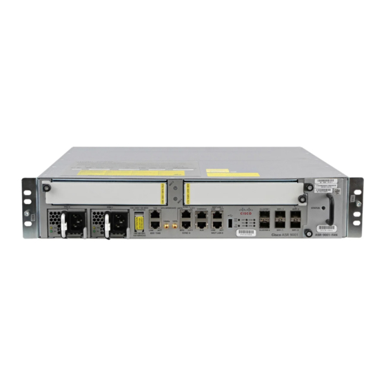
Front Panel of the Cisco ASR 9001 Router Cisco ASR 9001-S Router The Cisco ASR 9001-S Router is a 60 Gbps variant of the Cisco ASR 9001 Router. Similar to other routers in the Cisco ASR 9000 Series, running Cisco IOS XR software images, the Cisco ASR 9001-S Router delivers the features and services found on the ASR 9000 Series platforms, allowing customers to standardize on the same Cisco IOS XR image. -
Page 12: Safety Guidelines
Front Panel of the Cisco ASR 9001-S Router In order to achieve the full bandwidth of 120 Gbps and to enable the disabled ports, a Cisco license can be obtained. Once the license is obtained and installed, the Cisco ASR 9001-S Router must be reloaded to bring up the full 120 Gbps capacity. -
Page 13: Compliance And Safety Information
International Electrotechnical Commission (IEC) 364, part 1 through part 7. Compliance and Safety Information Both the Cisco ASR 9001 Router and the Cisco ASR 9001-S Router are designed to meet the regulatory compliance and safety approval requirements. See Regulatory Compliance and Safety Information for Cisco 12000 Series Routers. -
Page 14: Preventing Electrostatic Discharge Damage
1 Location of chassis socket for ESD strap on the Cisco ASR 9001 Router Lifting Guidelines A fully-configured Cisco ASR 9001 Router can weigh as much as 37.91 pounds (17.2 kg). These systems are not intended to be moved frequently. Before you install the router, ensure that you have planned the installation and migration of the router into your network so that you can avoid having to move the router later to accommodate power sources and network connections. -
Page 15: Site Requirement Guidelines
17.75 inches (45.09 cm) for the Cisco ASR 9001 Router. Height of the Cisco ASR 9001 Router is 3.47 inches (8.8 cm). • When fully populated with cards, the router can weigh as much as 37.91 pounds (17.2 kg). To •... - Page 16 To avoid noise interference in network interface cables, do not route them directly across or along • power cables. Figure 1-4 shows the top-down view chassis dimensions of the Cisco ASR 9001 Router. Figure 1-4 Cisco ASR 9001 Router Chassis Footprint and Dimensions—Top View Rear of chassis 17.42 Inch...
-
Page 17: Site Wiring Guidelines
Chassis Air Flow Guidelines Cool air is circulated through the Cisco ASR 9001 Router by one fan tray located along the right side of the router (see Figure 1-5). -
Page 18: Rack-Mounting And Air Flow Clearance Guidelines
18.31 inches ± 0.06 inch (46.50 cm ± 0.15 cm). Figure 1-6 shows examples of typical 2-post, 4-post, and telco-type equipment racks. Cisco ASR 9001 and Cisco ASR 9001-S Routers Hardware Installation Guide OL-26701-02... -
Page 19: Telco 2-Post Rack
Cisco ASR 9001 Router rack mounting). Two rear mounting brackets are provided for mounting the Cisco ASR 9001 Router in a 2-post rack. The mounting brackets on the Cisco ASR 9001 Router chassis have a pair of holes at the top and bottom Note of each bracket;... -
Page 20: Open 4-Post Rack
Two rear mounting brackets are provided for mounting the Cisco ASR 9001 Router in a 4-post rack. Enclosed Rack with Perforated Sides... -
Page 21: Air Flow Guidelines For Enclosed Rack Installation
Air Flow Guidelines for Enclosed Rack Installation To install a Cisco ASR 9001 Router in a 4-post enclosed cabinet, the front and rear doors of the cabinet must be removed or be perforated with a minimum of 65% open area (70% for ETSI 800mm racks). -
Page 22: Temperature And Humidity Guidelines
Ensure all power connection wiring conforms to the rules and regulations in the National Electrical Code (NEC) as well as local codes. Cisco ASR 9001 and Cisco ASR 9001-S Routers Hardware Installation Guide 1-12 OL-26701-02... -
Page 23: Ac Powered Routers
Chapter 1 Preparing for Installation Site Requirement Guidelines Each Cisco ASR 9001 Router is powered by only one type of input: AC or DC. A hybrid (AC+DC) Caution power configuration is not supported. Proper grounding is necessary to avoid damage from lightning and power surges. See the “NEBS... - Page 24 Connector: WS 002 Figure 1-11 AC Power Cord CAB-ACA Cordset rating: 10 A, 250 V Length: 8 ft 2 in. (2.5 m) Plug: NEMA L6-20 Connector: IEC 60320 C13 Cisco ASR 9001 and Cisco ASR 9001-S Routers Hardware Installation Guide 1-14 OL-26701-02...
- Page 25 Plug: EL 219 (IRAM 2073) Figure 1-14 AC Power Cord CAB-ACS Cordset rating: 10 A, 250 V Length: 8 ft 2 in. (2.5 m) Plug: NEMA L6-20P Connector: WS 002 Cisco ASR 9001 and Cisco ASR 9001-S Routers Hardware Installation Guide 1-15 OL-26701-02...
- Page 26 Figure 1-17 AC Power Cord CAB-ACSA Cordset rating: 10 A, 250 V Length: 8 ft 2 in. (2.5 m) Connector: IEC 60320 C15 Plug: EL 208 (SABS 164-1) Cisco ASR 9001 and Cisco ASR 9001-S Routers Hardware Installation Guide 1-16 OL-26701-02...
-
Page 27: Dc Powered Router
The length of the cables depends on your router location from the source power. Note DC power cables are not available from Cisco, but they are available from external commercial cable vendors. You must terminate DC power cables using terminal blocks. The terminal blocks are supplied along with the DC power supply modules from Cisco. - Page 28 Be sure uninsulated conductors are not accessible when cover is in place. Statement 1086 Only trained and qualified personnel should be allowed to install, replace, or service this equipment. Warning Statement 1030 Cisco ASR 9001 and Cisco ASR 9001-S Routers Hardware Installation Guide 1-18 OL-26701-02...
- Page 29 No damage should occur from reverse polarity, but you should correct a reverse polarity condition immediately. For a list of the nominal and acceptable value ranges for source DC power, see Table A-4 on page A-3. Cisco ASR 9001 and Cisco ASR 9001-S Routers Hardware Installation Guide 1-19 OL-26701-02...
-
Page 30: Nebs Supplemental Unit Bonding And Grounding Guidelines
For four AWG cable, use Panduit part number LCD4-14AF-L; for six AWG, use Panduit part number LCD6-14AF-L. Two 10-32 round-head screws and two locking washers (nickel-plated brass is ideal). • Cisco ASR 9001 and Cisco ASR 9001-S Routers Hardware Installation Guide 1-20 OL-26701-02... -
Page 31: Cisco Asr 9001 Router Port Connection Guidelines
Ports labeled Ethernet, SYNC, CONSOLE, and AUX are safety extra-low voltage (SELV) circuits. SELV Caution circuits should only be connected to other SELV circuits. In Cisco ASR 9001-S Router, two 10 GE fixed SFP+ ports (SFP+2 and SFP+3) are disabled by default, Note and can be enabled by a license upgrade. - Page 32 USB disk. Also, it can be used to transfer router log from the internal eUSB to the external memory stick. Signal type is NRZI. Cisco ASR 9001 and Cisco ASR 9001-S Routers Hardware Installation Guide 1-22 OL-26701-02...
-
Page 33: Console Port And Auxiliary Port Connection Guidelines
Request to Send — — (Not connected) Output Transmit data — Signal ground — Signal ground Input Receive data — — (Not connected) Input Clear to Send Cisco ASR 9001 and Cisco ASR 9001-S Routers Hardware Installation Guide 1-23 OL-26701-02... -
Page 34: Auxiliary Port Signals
Management LAN ports. Table 1-5 RP Management LAN Port Signals MGT LAN Port Pin 10Base-T, 100Base-TX Signal 1000Base-T Signal Transmit+ BI_DA+ Transmit– BI_DA– Receive+ BI_DB+ Cisco ASR 9001 and Cisco ASR 9001-S Routers Hardware Installation Guide 1-24 OL-26701-02... -
Page 35: Management Lan Port Led Indicators
Revision 01, February 1999, you must use a shielded cable when connecting the management LAN ports on the RP card. The shielded cable is terminated by shielded connectors on both ends, with the cable shield material tied to both connectors. Cisco ASR 9001 and Cisco ASR 9001-S Routers Hardware Installation Guide 1-25 OL-26701-02... -
Page 36: Sync Ports Connection Guidelines
The SYNC port connector has integral LED indicators (see Figure 1-27). When lit, these LEDs indicate: in BITS mode: • Green — Connection is alive. – Amber — A fault has occurred. – Cisco ASR 9001 and Cisco ASR 9001-S Routers Hardware Installation Guide 1-26 OL-26701-02... -
Page 37: Rp External Usb Port
RP External USB Port The Cisco ASR 9001 Router RP card has an external USB Type A slot accessible on the front panel. The front panel USB slot accepts widely available USB thumb drives. The only restriction on devices you can plug into the front panel external USB slot is that they need to be USB 2.0 devices. -
Page 38: C H A P T E R 1 Preparing For Installation Cisco Asr 9001 Router 1
Chapter 1 Preparing for Installation Cisco ASR 9001 Router Port Connection Guidelines Cisco ASR 9001 and Cisco ASR 9001-S Routers Hardware Installation Guide 1-28 OL-26701-02... -
Page 39: Pre-Installation Considerations And Requirements
ESD sockets on the front of the router chassis. For additional safety and compliance information, see the Regulatory Compliance and Safety Information for the Cisco ASR 9000 Series Aggregation Services Routers document that accompanied your router. -
Page 40: Required Tools And Equipment
(also called rails) in the rack. Three screws should be installed on each side of the chassis. Unpacking the Cisco ASR 9001 Router Follow these unpacking steps to unpack the Cisco ASR 9001 Router from its shipping container (see Figure 2-1). -
Page 41: C H A P T E R 2 Unpacking And Installing The Chassis
6 Foam packaging material - bottom cap Positioning the Router Use a safety hand truck to move the router to the location where it is being installed in a rack. Cisco ASR 9001 and Cisco ASR 9001-S Routers Hardware Installation Guide OL-26701-02... -
Page 42: Rack-Mounting The Router Chassis
Cisco ASR 9001 Router chassis. In a front-mounted position, the chassis rack-mounting flanges are secured directly to the rack posts. The PID of the rack mounting kit for Cisco ASR 9001 Router and Cisco ASR 9001-S Router is ASR-9001-2P-KIT=. Verifying Rack Dimensions... - Page 43 Rack-Mounting the Router Chassis This section describes how to install the chassis in a 2-post telco-style rack. Figure 2-3 shows the orientation of the Cisco ASR 9001 Router chassis to the rack posts and components used in the installation. Figure 2-3...
- Page 44 Fully tighten the two screws on each side bracket to secure the brackets to the chassis. Step 8 Step 9 Fully tighten the two screws on each side bracket flange to secure the brackets to the rack rails. Cisco ASR 9001 and Cisco ASR 9001-S Routers Hardware Installation Guide OL-26701-02...
-
Page 45: Installing The Chassis In A 4-Post Rack
Supplemental Bonding and Grounding Connections Installing the Chassis in a 4-post Rack To mount the Cisco ASR 9001 Router chassis in a 4-post open rack, two side brackets must be attached to the chassis and the rear posts (see Figure 2-5). - Page 46 Prepare the other end of the grounding wire, and connect it to the appropriate grounding point at your Step 3 site to ensure an adequate earth ground. Figure 2-6 NEBS Bonding and Grounding for the Cisco ASR 9001 Router Cisco ASR 9001 and Cisco ASR 9001-S Routers Hardware Installation Guide OL-26701-02...
-
Page 47: Fixed 4X10-Gigabit Ethernet Ports
Each fixed SFP+ port has an adjacent Link LED visible on the front panel. The Link LED indicates the status of the associated SFP+ port. In Cisco ASR 9001-S Router, two 10 GE fixed SFP+ ports (SFP+2 and SFP+3) are disabled by default, Note and can be enabled by a license upgrade. -
Page 48: Modular Port Adapters
4-Port 10-GE MPA • 2-Port 10-GE MPA • In Cisco ASR 9001-S Router, one ethernet pluggable port (MPA1) is disabled by default, and can be Note enabled by license upgrade. 20-Port Gigabit Ethernet Modular Port Adapter The 20-Port Gigabit Ethernet modular port adapter provides 10 double-stacked SFP (20 total) cages that support either fiber-optic or copper Gigabit Ethernet transceivers. -
Page 49: C H A P T E R 3 Installing Modules And Cables In The Chassis
The Link LED indicates the status of the associated XFP port, as described in Table 4-4. Refer to Figure 3-3 for an example of the 4-Port 10 Gigabit Ethernet modular port adapter. Cisco ASR 9001 and Cisco ASR 9001-S Routers Hardware Installation Guide OL-26701-02... -
Page 50: 2-Port 10 Gigabit Ethernet Modular Port Adapter
The Link LED indicates the status of the associated XFP port, as described in Table 4-4. Refer to Figure 3-4 for an example of the 2-Port 10 Gigabit Ethernet modular port adapter. Cisco ASR 9001 and Cisco ASR 9001-S Routers Hardware Installation Guide OL-26701-02... -
Page 51: Installing And Removing Modular Port Adapters
Handling Modular Port Adapters (MPAs), page 3-6 • Online Insertion and Removal, page 3-6 • • Modular Port Adapter (MPA) Installation and Removal, page 3-7 • Optical Device Installation and Removal, page 3-8 Cisco ASR 9001 and Cisco ASR 9001-S Routers Hardware Installation Guide OL-26701-02... -
Page 52: Handling Modular Port Adapters (Mpas)
(ESD) damage. Before you begin installation, refer to the Preparing to Install Modular Line Cards (MLCs) or Modular Port Adapters (MPAs) section of the Cisco ASR 9000 Series Aggregation Services Router Ethernet Line Card Installation Guide for a list of parts and tools required for installation. -
Page 53: Modular Port Adapter (Mpa) Installation And Removal
Hard OIR is the physical online insertion and removal of Modular port adapters (MPAs) without software commands. Four types of hard OIR are supported: If the bay is empty when the Cisco ASR 9001 Router modular line card (MLC) boots you can do the following: –... -
Page 54: Optical Device Installation And Removal
Using the ping Command to Verify Network Connectivity, page 3-10 • Verifying the Installation This section describes how to verify the modular port adapter (MPA) installation by observing the modular port adapter (MPA) LED states. Cisco ASR 9001 and Cisco ASR 9001-S Routers Hardware Installation Guide OL-26701-02... - Page 55 If a modular port adapter (MPA) does not meet the minimum version required, the FPD may need Note to be updated. Refer to Cisco ASR 9000 Series Aggregation Services Router System Management Configuration Guide for instructions. If the update fails, the failing module is powered down and an error message displays on the system console.
-
Page 56: Using Show Commands To Display Modular Port Adapter (Mpa) Information
Refer to Cisco ASR 9000 Series Aggregation Services Router Getting Started Guide and Cisco ASR 9000 Series Aggregation Services Router Interface and Hardware Component Configuration Guide for more information on bringing up and configuring the Cisco ASR 9000 Series Router and the Cisco ASR 9000 A9K-MOD80G-H. -
Page 57: Installing And Removing Sfp Modules
(powered on), and then repeat the ping command. Installing and Removing SFP Modules Refer to the Installing and Removing SFP Modules section on the Installing Line Cards in the Cisco ASR 9000 Series Router chapter of the Cisco ASR 9000 Series Aggregation Services Router Ethernet Line Card Installation Guide. -
Page 58: Cable Management
• A cable-management bracket Cable Management Tray A cable-management tray is mounted at the bottom of the Cisco ASR 9001 Router chassis for routing interface cables to the RP. Figure 3-6 shows a typical cable routing through the cable-management tray. -
Page 59: Removing A Cable-Management Tray
Step 4 Step Step 5 Loosen the captive installation screw on the cable-management tray and remove the tray from the chassis (see Figure 3-7). Cisco ASR 9001 and Cisco ASR 9001-S Routers Hardware Installation Guide 3-13 OL-26701-02... -
Page 60: Cable Management Bracket
Installing Modules and Cables in the Chassis Cable Management Cable Management Bracket The Cisco ASR 9001 Router provides a cable management bracket at the middle of the router chassis. Figure 3-8 shows a typical cable routing for the Cisco ASR 9001 Router. -
Page 61: Removing A Cable-Management Bracket
Step Loosen the captive installation screw on the cable-management bracket and remove the bracket from the Step 5 chassis (see Figure 3-9). Cisco ASR 9001 and Cisco ASR 9001-S Routers Hardware Installation Guide 3-15 OL-26701-02... -
Page 62: Connecting Route Processor Cables
SELV circuits. Note RP cables are not available from Cisco, but they are available from external commercial cable vendors. Note To comply with the intra-building lightning surge requirements of Telecordia GR-1089-CORE, Issue II, Revision 01, February 1999, you must use a shielded cable when connecting to the console, auxiliary, and Ethernet ports. -
Page 63: Connecting To The Rp Console Port
Ethernet management LAN ports. Note RJ-45 cables are not available from Cisco Systems; they are available from external commercial cable vendors. Use cables that comply with EIA/TIA-568 standards. Cisco ASR 9001 and Cisco ASR 9001-S Routers Hardware Installation Guide... -
Page 64: Connecting Power To The Router
Installing Modules and Cables in the Chassis Connecting Power to the Router Ethernet management ports are primarily used as Telnet ports into the Cisco ASR 9001, and for booting Caution or accessing Cisco software images over a network to which an Ethernet port is directly connected. We strongly caution you to consider the security implications of enabling routing functions on these ports. - Page 65 Plug the other end of the AC power cord into the AC source receptacle. Step 6 Proceed to the “Powering on the Router” section on page 3-21. Step 7 Cisco ASR 9001 and Cisco ASR 9001-S Routers Hardware Installation Guide 3-19 OL-26701-02...
-
Page 66: Connecting Power To A Dc-Powered Router
The length of the cables depends on the location of your router in relation to the source of DC power. Note These cables are not available from Cisco Systems. They are available from external commercial cable vendors. For more information on site power and source DC cable requirements, see the “Power... -
Page 67: Powering On The Router
Verify that the Power Input LED on each power module is lit. Step 3 Set the power switch to the ON position. Verify that the Green Power LED on each power module is lit. Step 4 Cisco ASR 9001 and Cisco ASR 9001-S Routers Hardware Installation Guide 3-21 OL-26701-02... - Page 68 Chapter 3 Installing Modules and Cables in the Chassis Powering on the Router Cisco ASR 9001 and Cisco ASR 9001-S Routers Hardware Installation Guide 3-22 OL-26701-02...
-
Page 69: Chapter 4 Troubleshooting The Installation
This section describes the methods used in troubleshooting the router. The troubleshooting methods are organized according to the major subsystems in the router. If you are unable to solve a problem on your own, you can contact a Cisco customer service representative for assistance. When you call, have this information ready: •... -
Page 70: Normal Router Startup Sequence
Processor subsystem—Includes the active Route Processor (RP) card with line card. The RP is • equipped with onboard processors. The RP downloads a copy of the Cisco software image to the line card processor. Cooling subsystem—Consists of one fantray with 14 fans, which circulate cooling air through the •... -
Page 71: Troubleshooting The Power Subsystem
Figure 4-1 shows the status indicators for the power module. The indicator definitions are provided after the figure. Cisco ASR 9001 and Cisco ASR 9001-S Routers Hardware Installation Guide OL-26701-02... - Page 72 If the OK LED is blinking, AC power input is operating normally, and the source AC input voltage of 100 to 240 VAC is within the nominal operating range. Cisco ASR 9001 and Cisco ASR 9001-S Routers Hardware Installation Guide OL-26701-02...
-
Page 73: Troubleshooting The Dc-Input Power Subsystem
Make sure that each power cable is connected to a dedicated DC power source. Verify that each DC power source is operating in the nominal range of –40 to –72 VDC. Cisco ASR 9001 and Cisco ASR 9001-S Routers Hardware Installation Guide OL-26701-02... -
Page 74: Additional Power Subsystem Troubleshooting Information
Hotspot0 37.5 host Hotspot0 43.5 host Hotspot1 37.8 host Hotspot2 45.7 host Hotspot3 41.6 host Hotspot4 45.9 host Inlet0 36.0 Voltage Information --------------------------------------------- R/S/I Modules Sensor (mV) Margin Cisco ASR 9001 and Cisco ASR 9001-S Routers Hardware Installation Guide OL-26701-02... - Page 75 VP1P5_DB 1499 host 1.2V_BLWDO 1200 host 1.0V_BLWDO 1000 host 1.8V_LC 1799 host 1.0V_FPGA_CORE_LC host 1.2V_LC 1199 host 1.2V_PHY_LDO 1200 host 0.9V_PHY_LDO host 0.9V_PHY_CORE host 1.0V_LC_MB host 3.3V_LC 3300 Cisco ASR 9001 and Cisco ASR 9001-S Routers Hardware Installation Guide OL-26701-02...
-
Page 76: Troubleshooting The Power Distribution System
Make sure the fan tray is operating: Step 2 If the fan tray is functioning, then the +12 VDC from the chassis backplane to the fan tray is • functioning properly. Cisco ASR 9001 and Cisco ASR 9001-S Routers Hardware Installation Guide OL-26701-02... -
Page 77: Troubleshooting The Route Processor Subsystem
+12 VDC distribution through backplane. • Contact your Cisco representative if replacing the fan tray does not fix the problem. Troubleshooting the Route Processor Subsystem The router processor subsystem consists of the route processor located on the RP card. The RP and the line card each has the same onboard CPU serving as the main processor. -
Page 78: Rp Front Panel Indicators
Time core is synchronized with external source excluding GPS and IEEE1588 FAIL/OK Bi-color Green Refer Figure 4-1 for detailed description. (Power Module) Amber Refer Figure 4-1 for detailed description. Cisco ASR 9001 and Cisco ASR 9001-S Routers Hardware Installation Guide 4-10 OL-26701-02... -
Page 79: Ethernet Ports And Status Leds
Auxiliary port—RJ45 interface that supports flow control and is often used to connect a modem, a • channel service unit (CSU), or other optional equipment for Telnet management. Console port—Receptacle (female) that provides a RJ45 interface for connecting a console terminal. • Cisco ASR 9001 and Cisco ASR 9001-S Routers Hardware Installation Guide 4-11 OL-26701-02... -
Page 80: Monitoring Critical, Major, And Minor Alarm Status
During a typical line card boot process, thse events occur: The line card receives power and begins executing initialization software. The line card performs internal checks, and prepares to accept the Cisco IOS XR software from the The RP loads the line card with its Cisco IOS XR software. -
Page 81: Configuring And Troubleshooting Line Card Interfaces
Configuration Parameters Table 4-5 lists the default interface configuration parameters that are present when an interface is enabled on a 10-Gigabit Ethernet line card. See Cisco IOS XR software documentation for complete information about these parameters. Table 4-5 Line Card Configuration Default Values... -
Page 82: Line Card Interface Address
Troubleshooting the Line Card Line Card Interface Address A Cisco ASR 9001 Router identifies an interface address by its rack number, line card slot number, instance number, and port number, in the format rack/slot/instance/port. The rack parameter is reserved for multirack systems; so, the rack parameter is always 0 (zero) for the Cisco ASR 9001 Router. -
Page 83: Verifying The Transceiver Modules
Step 7 If you want to disable the Cisco Discovery Protocol (CDP), which is not required, use this command: RP/0/RSP0/CPU0:router(config-if)# no cdp Add any other configuration subcommands required to enable routing protocols and adjust the interface Step 8 characteristics. - Page 84 PID: SFP-GE-S , VID: V01 , SN: FNS15501AK4 NAME: "module mau 0/0/1/15", DESCR: "SFP" PID: SFP-GE-S , VID: V01 , SN: FNS155009QS NAME: "module mau 0/0/1/16", DESCR: "SFP" Cisco ASR 9001 and Cisco ASR 9001-S Routers Hardware Installation Guide 4-16 OL-26701-02...
-
Page 85: Advanced Line Card Troubleshooting
This information is required when working on issues with the Cisco Technical Assistance Center (Cisco TAC). For examples of how to use these commands and the resulting output, see the Cisco ASR 9000 Series Troubleshooting Guide. Cisco ASR 9001 and Cisco ASR 9001-S Routers Hardware Installation Guide... -
Page 86: Troubleshooting The Cooling Subsystem
Power module detects an internal over-temperature condition. – Fault and Temp indicators light. Power module sends an over-temperature warning to the system and then power supply – switchover to the redundant power module. Cisco ASR 9001 and Cisco ASR 9001-S Routers Hardware Installation Guide 4-18 OL-26701-02... -
Page 87: Over-Temperature Conditions
If neither indicator is on and the blower is not operating, there may be a problem with either the fan • tray or the +12 VDC power supplied to the fan tray. Go to Step 2. Cisco ASR 9001 and Cisco ASR 9001-S Routers Hardware Installation Guide 4-19 OL-26701-02... - Page 88 Replace the fan tray. – If the new fan tray does not function, contact a Cisco customer service representative for assistance. If the Fault indicator is on, the power supply is faulty. Replace the power supply.
-
Page 89: Prerequisites And Preparation
Ensure that you have all the necessary tools and equipment before beginning the procedure. Have access to these documents during the installation: • Regulatory Compliance and Safety Information for the Cisco ASR 9000 Aggregation Services – Router publication that shipped with the router. -
Page 90: Online Insertion And Removal
Removing and Replacing the Fan Tray Online Insertion and Removal The Cisco ASR 9000 Series Router field-replaceable units (FRUs) can be removed and replaced with the power on and the system operating. This facility is known as online insertion and removal (OIR). Unless otherwise noted, the maintenance tasks described in this chapter can be performed while the router remains powered on. -
Page 91: Removing And Replacing Ac Or Dc Power System Components
Removing and Replacing AC or DC Power System Components Figure 5-1 Removing or Installing the Fan Tray on the Cisco ASR 9000 Series Router Chassis To install a fan tray into the chassis: Lift the fan tray (with two hands) and slide it halfway into the module bay. -
Page 92: Power Module Replacement Guidelines
Removing and Replacing AC or DC Power System Components Power Module Replacement Guidelines The Cisco ASR 9000 Series Router support online insertion and removal (OIR) for power modules. If you are replacing a redundant power module, you can remove and install the power module while the system remains powered on without causing an electrical hazard or damage to the system. -
Page 93: Installing An Ac Or Dc Power Module
24.69 pounds (11.2 kg) . Step 1 Power off the router (see the “Powering Off the Router” section on page 5-2). Step 2 Power off the circuit breakers to the power supplies. Cisco ASR 9001 and Cisco ASR 9001-S Routers Hardware Installation Guide OL-26701-02... -
Page 94: Installing A Replacement Chassis In The Equipment Rack
“Powering on the Router” section on page 3-21. Step 5 Packing a Chassis for Shipment Use the packaging that came with the replacement chassis to repack and ship the chassis being replaced. Cisco ASR 9001 and Cisco ASR 9001-S Routers Hardware Installation Guide OL-26701-02... -
Page 95: Appendix
A P P E N D I X Technical Specifications This appendix lists certain technical specifications for the Cisco ASR 9001 Router. The specifications are presented in these tables: Table A-1, Cisco ASR 9001 Router Physical Specifications • • Table... - Page 96 (This refers to a total of 360 hours in any given year, but no more than 15 occurrences during that 1-year period.). 2. G is a value of acceleration, where 1G equals 32.17 ft/sec (9.81 m/sec 3. Grms is the root mean square value of acceleration. Cisco ASR 9001 and Cisco ASR 9001-S Routers Hardware Installation Guide OL-26701-02...
- Page 97 1. For each DC power supply module. Some power/chassis configurations may operate at lower current ratings than those specified in this table. Contact your Cisco technical representative for more information. Cisco ASR 9001 and Cisco ASR 9001-S Routers Hardware Installation Guide...
- Page 98 Appendix A Technical Specifications Table A-5 lists the AC input voltage range for the AC-powered Cisco ASR 9001 Router (single phase power source). Table A-5 AC Input Voltage Range Minimum Maximum Range Minimum Nominal Nominal Nominal Maximum Input Voltage 90 VAC...
- Page 99 Table A-11 Supported SFP+ Transceivers Typical Maximum Part Number Description Wavelength Fiber Type Distance SFP-10G-ER Cisco SFP+ for 10-Gigabit Ethernet 1550 nm 24.85 miles Extended Reach (40 km) Cisco ASR 9001 and Cisco ASR 9001-S Routers Hardware Installation Guide OL-26701-02...
- Page 100 Cisco 1000BASE-DWDM SFP (100 GHz ITU grid) 1553.32 nm DWDM-SFP-5252 Cisco 1000BASE-DWDM SFP (100 GHz ITU grid) 1552.52 nm DWDM-SFP-5172 Cisco 1000BASE-DWDM SFP (100 GHz ITU grid) 1551.72 nm Cisco ASR 9001 and Cisco ASR 9001-S Routers Hardware Installation Guide OL-26701-02...
- Page 101 EEPROM that is security-programmed by the SFP manufacturer with information that provides a way for Cisco IOS XR software to identify and validate the SFP module to operate properly with Cisco Ethernet line cards. Unapproved SFP modules (those not purchased directly from Cisco Systems, Inc.) do not work on the Ethernet line card.
- Page 102 Cisco 10GBASE-DWDM XFP (100 GHz ITU grid) 1548.51 nm DWDM-XFP-47.72 Cisco 10GBASE-DWDM XFP (100 GHz ITU grid) 1547.72 nm DWDM-XFP-46.92 Cisco 10GBASE-DWDM XFP (100 GHz ITU grid) 1546.92 nm Cisco ASR 9001 and Cisco ASR 9001-S Routers Hardware Installation Guide OL-26701-02...
- Page 103 Cisco 10GBASE-DWDM XFP (100 GHz ITU grid) 1531.12 nm DWDM-XFP-30.33 Cisco 10GBASE-DWDM XFP (100 GHz ITU grid) 1530.33 nm DWDM-XFP-C Cisco 10GBASE-DWDM Tunable XFP (50-GHz ITU grid) 80 Variable Variable Channels Cisco ASR 9001 and Cisco ASR 9001-S Routers Hardware Installation Guide OL-26701-02...
- Page 104 Appendix A Technical Specifications Cisco ASR 9001 and Cisco ASR 9001-S Routers Hardware Installation Guide A-10 OL-26701-02...
-
Page 105: Appendix
A sample site log format is provided in the next page. You can make copies of the sample, or design your own site log page to meet the customized needs of your site and equipment. Cisco ASR 9001 and Cisco ASR 9001-S Routers Hardware Installation Guide OL-26701-02... - Page 106 Appendix B Site Log Date Description of Action Performed or Symptoms Observed Initials Cisco ASR 9001 and Cisco ASR 9001-S Routers Hardware Installation Guide OL-26701-02...
-
Page 107: I N D E X
ASR 9006 3-14 alarms cable-management tray, ASR 9010 3-12 front panel indicators, RSP card 4-10 cable-management system recommendations line cards 4-12 cables Cisco ASR 9001 and Cisco ASR 9001-S Routers Hardware Installation Guide IN-1 OL-26701-02... - Page 108 (warning) AC-powered routers 1-13 packing for shipment cables to RSP card 3-16 rack installation DC-powered routers 1-17 removal warning ESD wrist strap to chassis Cisco ASR 9001 and Cisco ASR 9001-S Routers Hardware Installation Guide IN-2 OL-26701-02...
- Page 109 4-18 power shelf, correct polarity on cable installing in the chassis connections 3-20 LEDs at startup power system operation 4-18 electrical specifications removing rated input voltage Cisco ASR 9001 and Cisco ASR 9001-S Routers Hardware Installation Guide IN-3 OL-26701-02...
- Page 110 4-13, 4-17 sample site log line card status LED 4-12 interface address 4-14 line frequency, AC-input power supply interface command 4-14 interface configuration mode 4-14 interfaces Cisco ASR 9001 and Cisco ASR 9001-S Routers Hardware Installation Guide IN-4 OL-26701-02...
- Page 111 OIR (online insertion and removal) DC-input for SPAs input current rating online insertion and removal rated input voltage overtemperature conditions 4-19 service requirement installing removing power supplies Cisco ASR 9001 and Cisco ASR 9001-S Routers Hardware Installation Guide IN-5 OL-26701-02...
- Page 112 4-10 removing chassis from front panel (illustration) telco 2-post ports description See console port; auxiliary port; management illustration 1-10 LAN port; sync port Cisco ASR 9001 and Cisco ASR 9001-S Routers Hardware Installation Guide IN-6 OL-26701-02...
- Page 113 1-20 line cards 4-13, 4-17 temperature and humidity 1-12 overview site wiring power distribution system guidelines power subsystem specifications power system AC-input power subsystem RP subsystem Cisco ASR 9001 and Cisco ASR 9001-S Routers Hardware Installation Guide IN-7 OL-26701-02...
- Page 114 UTI connector pinout 1-27 verifying equipment rack dimensions (illustration) rack dimensions Verifying the VIP4 Installation verifying transceiver modules 4-15 vibration specifications, system voltage AC-input power module AC-input power supply Cisco ASR 9001 and Cisco ASR 9001-S Routers Hardware Installation Guide IN-8 OL-26701-02...