Table of Contents
Advertisement
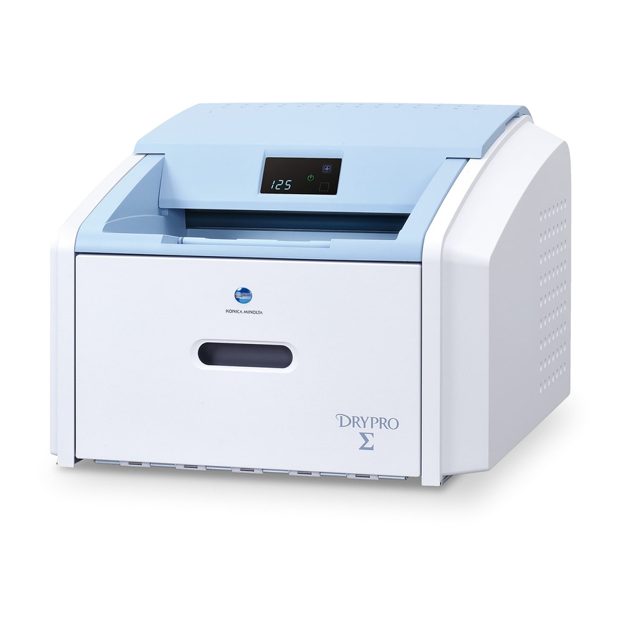
KONICA MINOLTA DRYPRO SIGMA Laser Imaging System
Film Types
The DRYPRO SIGMA Laser Imager prints on KONICA MINOLTA Medical Imaging Film.
Intended Use
The DRYPRO SIGMA Laser Imaging System is intended to provide hard copy images
from digital imaging source output signals onto KONICA MINOLTA MEDICAL IMAGING
FILM SD-S. The device is intended for use with a variety of digital modalities,
including, but not limited to, CR (Computed Radiology), DR (Digital Radiology), CT
(Computerized Tomography) and MRI (Magnetic Resonance Imaging). The images
are to be used for medical diagnosis and referral to physicians and their patients.
This device is not intended to be used with Full Field Digital Mammography units or
Computed Radiography units supporting digital mammography.
Getting Started
Your laser imager comes with several publications to help you get started quickly and
safely. Locate the following publications:
• Safety Manual (9G7565): Review this manual first to understand how to position and work
with the laser imager safely and within regulations.
• Pre-Installation Manual (9G7563): Ensure that your site is ready for the installation.
• Installation Manual (9G7567): Learn how to install the laser imager.
• Operation Manual (9G7564): See this guide for a product overview, use instructions, and
troubleshooting tips.
• Quick Reference Card (9G7566): Keep this card in a convenient place and reference it as
needed.
Pub history:
A: 2011-03-31. First release.
B: Updated the company name.
Pub No. 9G7571_en, Rev. B, 2013-04-01
© KONICA MINOLTA, INC., 2013
KONICA MINOLTA and DRYPRO are trademarks of KONICA
MINOLTA, INC.
KONICA MINOLTA, INC.
1 Sakura-machi, Hino-shi, Tokyo, 191-8511, Japan
Advertisement
Chapters
Table of Contents
Troubleshooting

Related Manuals for Konica Minolta DRYPRO SIGMA


Summary of Contents for Konica Minolta DRYPRO SIGMA
-
Page 1: Film Types
The DRYPRO SIGMA Laser Imager prints on KONICA MINOLTA Medical Imaging Film. Intended Use The DRYPRO SIGMA Laser Imaging System is intended to provide hard copy images from digital imaging source output signals onto KONICA MINOLTA MEDICAL IMAGING FILM SD-S. The device is intended for use with a variety of digital modalities, including, but not limited to, CR (Computed Radiology), DR (Digital Radiology), CT (Computerized Tomography) and MRI (Magnetic Resonance Imaging). -
Page 2: Installation Manual
Installation Manual Requirements to install the laser imager CAUTION The laser imager weighs approximately 54 kg (120 lb). Two people must use safe lifting techniques to move the laser imager. One person can complete the remaining steps. The installation must be performed by qualified personnel. Task Recommended Skill or Knowledge Unpack the laser imager. - Page 3 Unpacking the laser imager Checking the Check that the following items are included in the accessories box: accessories • Power cord • Network cable • Deodorant filter • Publications kit IMPORTANT: Please read the Safety Manual before you proceed to install or operate the laser imager.
- Page 4 Moving the shipping Shipping brackets are fastened inside the laser imager to keep the parts brackets and retainer safe during shipment. You must remove them, and then reinstall them in a different location (as shown) inside the laser imager. This prevents the shipping brackets from becoming lost.
- Page 5 To move the front shipping bracket, remove 4 screws that fasten the shipping bracket. Front view of laser imager Shipping Bracket FRONT SHIPPING BRACKET (FILTER REMOVED Use 2 of the screws to reattach the shipping bracket in the alternate set of holes on the left side of the rail. Shipping Bracket reattached...
- Page 6 Behind the right cover, locate the tie wrap that fastens the exposure transport belt. The tie wrap removes tension from the belt during shipping. Cut and remove the tie wrap from the belt. Tie Wrap H221_6030GC Install the deodorant filter. Film Supply Filter Reinstall the right and top covers.
- Page 7 Connecting to electrical power Locate the power cord. The power cord must match the AC power outlets at your site. If you cannot use the power cord that is provided, obtain a suitable power cord locally. You must use an agency-approved power cord rated for adequate amperage with a plug type suitable for your location.
-
Page 8: Applying Power
Applying power Check that the film supply is closed. To start the laser imager, press the power switch on the back of the laser imager to on (|). Wait as the laser imager warms up. The warm-up period might last up to 30 minutes. The display screen shows the progress as the laser imager becomes ready to print. - Page 9 Configuring the laser imager Setting up your Do this procedure at your computer. computer to Select Start>Settings>Network Connections. communicate with the NOTE: Depending on your operating system, this might be Start>Settings>Network and Dial-up Connections. laser imager Right-click Local Area Connection. Select Properties.
- Page 10 Configuring Start MICROSOFT INTERNET EXPLORER. site-specific information In the Address box, type: 192.168.0.1 Click Go. The main screen for the Web Portal appears. If you are using INTERNET EXPLORER 8, set the IE8 window to compatibility view. Click the Compatibility View toolbar button. This will correct some potential viewing issues with IE8.
- Page 11 NOTE: This information should have been gathered in the Pre-Installation Manual. If you need help, see your network administrator. Click Save. Click . The Clock Configuration screen appears. IMPORTANT: The system clock is set before the laser imager is shipped to you. If the time zone is not correct, change it. When you change the time zone, the time and date display correctly.
-
Page 12: Completing The Installation
Wait for the laser imager to restart. The laser imager requires approximately 30 minutes to warm up. After completing the warm-up cycle, the laser imager may print a calibration film if the film cartridge requires it. While the laser imager is warming up, continue with the next step. Completing the installation Laser Imager Back Panel... -
Page 13: Troubleshooting
Troubleshooting CAUTION Laser imager does not Never pull on the cord to disconnect the plug from the wall outlet. Grasp the plug and pull to disconnect. start Press the power switch on the back of the laser imager off(0), and then on (|), to restart the laser imager. - Page 14 Display Web Portal Action Screen Portal Message 21175 Rollback If the Pause symbol is on, press Failed to it to cover the film cartridge. Engage When the Pause symbol stops Cartridge flashing, remove the film cartridge from the laser imager. Insert a different film cartridge into the laser imager.
- Page 15 KONICA MINOLTA, INC. 1 Sakura-machi, Hino-shi, Tokyo, 191-8511, Japan KONICA MINOLTA, INC., 2015 © Pub No. 9G7567_en Rev C...
- Page 16 Operation Manual Publication No. 9G7564_en 2013-04-01...
- Page 17 All rights reserved. No part of this manual may be reproduced or copied in any form by any mean graphic, electronic, or mechanical, including photocopying, typing, or information retrieval systems without written permission.
-
Page 18: Table Of Contents
Contents 1 Overview How the Imager Works ......................... 1-4 Print Sequence ......................... 1-4 Film Sizes ..........................1-5 Automatic Image Quality and Processing ................1-5 Configure and Monitor the System (Using the Web Portal) ..........1-5 Agency Compliance ......................... 1-6 Operation Manual Conventions ..................... 1-6 2 Basic Operating Tasks Understanding the Display Screen .................... - Page 19 Condition Codes .......................... 3-10 Film Jam Indication and Areas ....................3-16 Clear Film Jam Code 116 / Jam in Area 1 ................3-18 Clear Film Jam Code 323 / Jam in Area 2 ................3-18 Clear Film Jam Code 324 or 325 / Jam in Area 2 ..............3-19 Clear Film Jam Code 326 / Jam in Area 2 or 3 ..............
-
Page 20: Overview
Overview The Laser Imaging System is a continuous-tone laser imager with an internal photothermographic film processor. Heat, rather than photo chemicals, is used to develop the film. This easy-to-use and reliable imager provides high quality prints. Use the prints from this system for: •... - Page 21 Overview Power switch. The power switch is on the back. Exit tray. Extend the exit tray to hold large film (35 x 43 cm, or 14 x 17 in.) as it finishes printing. It can hold up to 50 processed sheets of film. Major Internal Assemblies H210_1012HC Exposure transport.
- Page 22 Overview Pickup assembly. Lifts a single sheet of film from the supply cartridge and feeds it into the rollers. Exit rollers. Moves the film from the processor area to the exit tray. Rollback assembly. Rolls the film cartridge cover back so the pickup assembly can lift the film.
-
Page 23: How The Imager Works
Overview How the Imager Works The imager receives, processes, manages, and prints the images on film. The imager has limited storage to hold a small number of digital images. As images are received for printing, they are stored in memory, placed in a sequential print queue, and are printed in order. -
Page 24: Film Sizes
Overview Film Sizes The imager supports four sizes: • 35 x 43 cm (14 x 17 in.) • 28 x 35 cm (11 x 14 in.) • 25 x 30 cm (10 x 12 in.) • 20 x 25 cm (8 x 10 in.) For the specific films that are supported, see the Publications Cover Page. -
Page 25: Agency Compliance
Overview Agency Compliance See the Safety Manual. Operation Manual Conventions The following special messages emphasize information or indicate potential risks to personnel or equipment. Note Notes provide additional information, such as expanded explanations, hints, or reminders. Important Important notes highlight critical policy information that affects how you use this guide and this product. -
Page 26: Basic Operating Tasks
Basic Operating Tasks During normal operation, the imager receives and automatically prints images sent by modalities over a network. Very little interaction is required. You may do the following: • Turn the power on (|) and off (0). • Load film cartridges. •... -
Page 27: Understanding The Display Screen
Basic Operating Tasks Understanding the Display Screen The display screen communicates the status of the imager. Symbol or code Description Top left of the Error or status code. The 3-digit code displays when the error or status con- display screen: dition is present. - Page 28 Basic Operating Tasks Symbol or code Description Restart Restart the imager. An error code also displays. Film Jam Film is jammed. The error code confirms the film jam and gives direction on where to find the film inside the imager. Maintenance Preventive maintenance is required.
-
Page 29: Turning The Power On And Off
Basic Operating Tasks Turning the Power On and Off 1. To start the imager, press the power switch on the back of the imager to on (|). 2. Wait as the imager warms up. The warm-up period might last up to 30 minutes. The display screen shows the progress as the imager becomes ready to print. -
Page 30: Restarting The Imager
Basic Operating Tasks Restarting the Imager If the imager encounters an error that is usually corrected with a restart, the display screen shows the Restart symbol. Figure 3: The error code indicates the error condition. You may want to check the Troubleshooting chapter or the Quick Reference Card to identify the error. -
Page 31: Film Cartridge Information
Basic Operating Tasks Film Cartridge Information Film Count The film count displays on the imager display screen. Figure 4: In the example, 125 indicates a full film cartridge. Size of the Loaded Film The film size displays in the same location as the film count. The display screen alternates between the film count and the size of the loaded film. -
Page 32: Insert A New Film Cartridge
Basic Operating Tasks Insert a New Film Cartridge Prerequisites: Before you load a new film cartridge, make sure that the Pause symbol is off. During normal operation, the symbol is off. When the film cartridge cover is open, the symbol is on. -
Page 33: Load A Different Film Size To Match A Print Request
Basic Operating Tasks Load a Different Film Size to Match a Print Request If a print request requires a different film size, the requested film size flashes on the display screen. Change the installed film to match the print request. Figure 7: The requested film size (in this example, “35”... -
Page 34: Delete Pending Jobs
Basic Operating Tasks Delete Pending Jobs You might cancel all the pending print requests if the wrong media has been selected. To cancel all print requests, press and hold the Film Size symbol for five seconds. Figure 8: Press the yellow Film Size symbol for five seconds. Note •... -
Page 35: Calibrate The Imager For The Installed Film
Basic Operating Tasks Calibrate the Imager for the Installed Film In normal operating conditions, it is not necessary to calibrate the imager for the film. Run a calibration when: • Code 001 appears on the display screen. • A calibration error occurs, indicated by codes 624, 631, or 632 on the display screen. •... -
Page 36: Open Or Remove A Cover
Basic Operating Tasks Open or Remove a Cover You can open or remove the imager’s top cover, left cover, and film supply. The covers are protected with an interlock mechanism to keep the imager from printing when they are open. The imager is not operational when an interlock is open. Code 701 alerts you that a cover and an interlock are open, and internal power has been removed from the operator accessible areas. -
Page 37: Additional Functionality With The Web Portal
Basic Operating Tasks Additional Functionality with the Web Portal The Web Portal is your interface to additional features. In addition to the installation and setup of your system, you can view and manage the imager's connections over the network, configure features, view error messages and access general status information at the Web Portal. -
Page 38: Maintenance And Troubleshooting
Maintenance and Troubleshooting Use the information in this chapter to keep the laser imager in the best condition and to correct minor problems. • Overview: Status and Error Messages and Codes • Preventive Maintenance—Learn how to respond to the Maintenance symbol when it appears •... -
Page 39: Preventive Maintenance
Maintenance and Troubleshooting Preventive Maintenance Note These conditions are also reported at the Web Portal. About the Filter Caution In the U.S., exhausted filters are considered to be non-hazardous waste according to the US Environmental Protection Agency Resource Conservation Recovery Act (RCRA). Municipality owned and licensed solid waste management facilities are an appropriate disposal option. -
Page 40: 550 Code And Maintenance Symbol
Maintenance and Troubleshooting 3. Install a new deodorant filter. 4. Close the film supply. 5. To reset the laser imager for the new filter and to clear the Maintenance symbol, press and then release the Maintenance and Calibrate symbols at the same time. 550 Code and Maintenance Symbol If the imager needs a preventive maintenance service call, the 550 code and Maintenance symbol appear:... -
Page 41: Error Indicators On The Display Screen
Maintenance and Troubleshooting Error Indicators on the Display Screen The imager can detect errors and other conditions that require a response. Some errors or abnormal conditions are reported on the display screen in the form of condition codes and symbols. Note These errors are also reported at the Web Portal. -
Page 42: Using The Web Portal To Gain More Information On Errors
Maintenance and Troubleshooting Using the Web Portal to Gain More Information on Errors The Web Portal is your interface to additional functions on the imager. You can view and correct error messages and access general status information at the Web Portal. About the Codes on the Web Portal and the Display Screen The 3-digit error and status codes on the display screen are reported at the Web Portal as 5-digit codes. -
Page 43: Subsystem Error Codes And Messages
Maintenance and Troubleshooting Subsystem Error Codes and Messages Use the information in this section to interpret the codes and messages that appear on the display screen and at the Web Portal. DICOM (Digital Imaging and Communications in Medicine) In response to a DICOM printer N-GET status request from a modality, a printer status message and a printer status info message are returned to the requesting service class user (SCU). -
Page 44: Printer
Maintenance and Troubleshooting Printer Printer Status Display Screen Web Portal DICOM Status Description Cover is open Code: 701 20701: WARNING / The top cover is open or one Cover COVER OPEN of the side panels may be off. Power symbol is Open The laser imager is not ready yellow... -
Page 45: Film Cartridge
Maintenance and Troubleshooting Film Cartridge Film Cartridge State Display Screen Web Portal Description Failed Power symbol is yellow Failed An error has occurred that affects normal operation. This Pause and Calibrate symbols film cartridge is currently not are off usable. Reinsert the cartridge. Film count is replaced by If error reoccurs, insert a new dashes... -
Page 46: Job Manager
Maintenance and Troubleshooting Film Cartridge State Display Screen Web Portal Description Not ready Various Not Ready When the conditions are cor- rected, the laser imager can print. Cartridge closure is Power symbol is green Pause Requested You pressed the Pause button, pending but the rollback has not Calibrate symbol is off... -
Page 47: Condition Codes
Maintenance and Troubleshooting Condition Codes Condition codes are shown on the display screen in the order in which they are generated. If there is more than one code associated with the current condition of the laser imager, the first code is shown on the display screen for six seconds, while other codes in the list display for three seconds as the list is cycled. - Page 48 Maintenance and Troubleshooting Display Screen Portal Web Portal Message Action 20154 MCS: Internal Com- Restart the laser imager. munications Failure If the error persists, call for service. 20155 Incompatible MCS Restart the laser imager. Printer Configura- If the error persists, call for service. tion for Hardware 20156 Incompatible Soft-...
- Page 49 Maintenance and Troubleshooting Display Screen Portal Web Portal Message Action 21118 Film Supply: Inter- If the Pause symbol is on, press it to cover the nal Hardware Failure film cartridge. When the Pause symbol stops flashing, remove the film cartridge from the laser imager.
- Page 50 Maintenance and Troubleshooting Display Screen Portal Web Portal Message Action 21177 Film Cartridge Failed Open the film supply. Manually close the film to Close cartridge, using the manual rollback knob, to prevent the film from fogging. If the error persists, call for service. 21178 Rollback Failed to If the Pause symbol is on, press it to cover the...
- Page 51 Maintenance and Troubleshooting Display Screen Portal Web Portal Message Action 26544 Film Jam in Area 3 Clear the jam. 27123 Optics: Internal Restart the laser imager. Hardware Failure If the error persists, call for service. 27601 Optics: Calibration Restart the laser imager. Failed If the error persists, call for service.
-
Page 52: Related Topics
Maintenance and Troubleshooting Display Screen Portal Web Portal Message Action 29931 Densitometer: Inter- Restart the laser imager. nal Communica- If the error persists, call for service. tions Failure 36935 Local Panel: No Restart the laser imager. Communications If the error persists, call for service. from MCS Related topics Restarting the Imager... -
Page 53: Film Jam Indication And Areas
Maintenance and Troubleshooting Film Jam Indication and Areas Jam Areas When film is jammed, the display screen indicates a jam and an error code that provides guidance on where to check for the jammed film. Check the code to locate the jammed film. - Page 54 Maintenance and Troubleshooting Roller Knobs For some jams, you can remove the film by turning a knob to move the film out of the imager. See details in the film jam instructions. Figure 2: Knobs for manual film removal Item Description Processor drum knob Exit roller knob...
-
Page 55: Clear Film Jam Code 323 / Jam In Area 2
Maintenance and Troubleshooting Clear Film Jam Code 116 / Jam in Area 1 Note This error displays as code 21116 at the Web Portal. 1. If the Pause symbol is on, press it and wait until it goes off. 2. Open the film supply and remove the film cartridge from the imager. 3. -
Page 56: Clear Film Jam Code 324 Or 325 / Jam In Area 2
Maintenance and Troubleshooting Clear Film Jam Code 324 or 325 / Jam in Area 2 Note This error displays as code 26324 or 26325 at the Web Portal. 1. If the Pause symbol is on, press it and wait until it goes off. 2. -
Page 57: Clear Film Jam Code 326 / Jam In Area 2 Or 3
Maintenance and Troubleshooting Clear Film Jam Code 326 / Jam in Area 2 or 3 Note This error displays as code 26326 at the Web Portal. 1. If the Pause symbol is on, press it and wait until it goes off. 2. -
Page 58: Clear Film Jam Code 543 Or 544 / Jam In Area 3
Maintenance and Troubleshooting Clear Film Jam Code 543 or 544 / Jam in Area 3 Note This error displays as code 26543 or 26544 at the Web Portal. 1. Remove any film that is jammed from the exit tray. 2. If the Pause symbol is on, press it and wait until it goes off. 3. -
Page 60: Film Technical Information
Film Technical Information This section describes the characteristics of Laser Imaging Film, not the operation of the laser imager. The Laser Imaging Film is a high-resolution, infrared-sensitive, photothermographic film designed specifically for the laser imager. Spectral Sensitivity The Laser Imaging Film is infrared sensitive and has been sensitized to the infrared laser diode of the laser imagers. -
Page 61: Environmental Impact
Film Technical Information Environmental Impact Tests show that the Laser Imaging Film is not considered hazardous to the environment. As a result, you can develop, recycle, and dispose of film with less impact on the environment than if you were using wet-developed silver halide films. Table 1: Laser Imaging Film—US Environmental Regulations Comparison Wet (Silver Halide) Film Dry Film... -
Page 62: Developed Film Handling And Archival
Film Technical Information Developed Film Handling and Archival Handling the Laser Imaging Film requires reasonable care. Spills, humidity, and other moisture typically have no significant effect on developed films. However, prolonged exposure to intense light or excessive heat (54.4 °C or 130.0 °F) for more than three hours may cause some gradual darkening of images. -
Page 63: Odor Dissipation
Film Technical Information Odor Dissipation Dry technology eliminates virtually all unpleasant odors. While some low-level odors are produced during the development process, they pose no known adverse health risks. Processing odor levels are further reduced by a non-hazardous, recyclable filter in the laser imager. -
Page 64: Specifications
Specifications Equipment Specifications Unpacked Packed Height 47 cm (19 in.) 74 cm (29 in.) Width 61 cm (24 in.) 79 cm (31 in.) Depth 66 cm (26 in.) 85 cm (34 in.) Weight 54 kg (120 lb) 73 kg (160 lb) Operating Space Requirements •... -
Page 65: Environmental Effects
Specifications Environmental Effects Acoustical noise: • Less than 55 dB at 1.5 m during idle or standby • Less than 75 dB momentary at 1 m during normal operation Power Requirements A power cord is provided with this equipment. All countries must use an Agency- approved power cord with a plug type suitable for the country of use. -
Page 66: Publication History
Publication History Revision Date Reason for Change 2011-03-31 First release 2013-04-01 Updates for UL 3rd edition and corporate updates 9G7564_en | 2013-04-01 6–1... - Page 67 KONICA MINOLTA, INC. 1 Sakura-machi, Hino-shi, Tokyo, 191-8511, Japan © KONICA MINOLTA, INC., 2013 Printed in China. Pub No. 9G7564_en Rev B...
-
Page 68: Location Requirements
74 cm (29 in.) Width 61 cm (24 in.) 79 cm (31 in.) Depth 66 cm (26 in.) 85 cm (34 in.) Weight 54 kg (120 lbs) 73 kg (160 lbs) © KONICA MINOLTA, INC., 2013 2013-04-01 Pub No. 9G7563_en... - Page 69 Film Prior to installation, you must order and have available the appropriate film. The laser imager Ready? prints on KONICA MINOLTA Medical Imaging Film in the following sizes: • 20 x 25 cm (8 x 10 in.) • 25 x 30 cm (10 x 12 in.) •...
- Page 70 Safety Manual Publication No. 9G7565_en 2015-10-16 Supersedes: 2015-09-14...
- Page 71 All rights reserved. No part of this manual may be reproduced or copied in any form by any means—graphic, electronic, or mechanical, including photocopying, typing, or information retrieval systems—without written permission.
- Page 72 Contents Safety and Related Information Safety, Warnings, and Cautions....................... 2 Safety Labels ..........................5 System Labels ..........................6 Safety and Health Compliance ......................9 Safety Standards ......................... 9 EMC Standards.......................... 10 EU Directives ..........................15 CE Marking..........................15 Publication History 9G7565_en | 2015-10-16...
-
Page 74: Safety And Related Information
Safety and Related Information The information contained herein is based on the experience and knowledge relating to the subject matter gained by the manufacturer prior to publication. No patent license is granted by this information. The manufacturer reserves the right to change this information without notice and makes no warranty, express or implied, with respect to this information. -
Page 75: Safety, Warnings, And Cautions
Safety, Warnings, and Cautions Safety, Warnings, and Cautions Please read and understand all instructions before using this product. DANGER This equipment is operated with hazardous voltage which can shock, burn, or cause death. • Remove wall plug before servicing equipment. Never pull on cord to remove from outlet. Grasp plug and pull to disconnect. - Page 76 Safety, Warnings, and Cautions Caution Do not use in the presence of flammable anesthetics, oxygen, or nitrous oxide. This equipment does not have a gas-sealed electronics enclosure and could ignite any flammable or explosive gases present in its environment. Caution This equipment uses a DICOM network port, and is intended to connect to other medical devices over the network.
- Page 77 Safety, Warnings, and Cautions Caution In the U.S., exhausted filters are considered to be non-hazardous waste according to the US Environmental Protection Agency Resource Conservation Recovery Act (RCRA). Municipality owned and licensed solid waste management facilities are an appropriate disposal option. Contact your local or state solid waste authorities to determine if additional disposal requirements apply.
-
Page 78: Safety Labels
Safety, Warnings, and Cautions Safety Labels Safety labels are attached to the laser imager in compliance with international standards. English Text on Labels Some names on the labels are shortened and left in English. Below is a key to understand the meanings of the shortened words on the labels: Symbol on label Definition... -
Page 79: System Labels
Safety, Warnings, and Cautions System Labels Laser Radiation Warning Class 3B invisible laser radiation. This label states: “When open and interlocks defeated, avoid exposure to the beam.” Hazard symbol Table 1: Laser specifications Scanning (moving) laser beam emitting from a diode Type 810 ±10 nanometers Wavelength... - Page 80 Safety, Warnings, and Cautions Back Panel and Agency Statements Figure 1: Laser Imager Back Panel Item Label Description FCC compliance Describes compliance, if applicable for the country of installa- tion. Product States that the imager is a Laser Imaging Printer. 9G7565_en | 2015-10-16...
- Page 81 Safety, Warnings, and Cautions Item Label Description • High voltage. Indicates that high voltage is present Agency labels and under panels where the label is attached. Only an autho- Class 1 Laser Safety rized service provider should attempt access. • Static Sensitive Equipment.
-
Page 82: Safety And Health Compliance
Safety and Health Compliance Safety and Health Compliance This equipment has been tested for and complies with the following Safety and Emissions Standards. Certificates of Compliance and Declarations of Conformity have been issued. Safety Standards United States • FDA 21CFR 807 Subpart E - Premarket Notification Procedures. •... -
Page 83: Emc Standards
Safety and Health Compliance EMC Standards United States • FCC Rules and Regulations, Title 47, Part 15, Subpart B, Class A: Radio Frequency Devices: Unintentional Radiators. • This equipment has been tested and been found to comply with the limits for a Class A digital device pursuant to part 15 of the FCC rules. - Page 84 Safety and Health Compliance Guidance and Manufacturer’s Declaration for Electromagnetic Emissions The equipment is intended for use in the electromagnetic environment specified below. The customer or user of the equipment should ensure that it is used in such an environment. Emissions Test Compliance Electromagnetic Environment—Guidance...
- Page 85 Safety and Health Compliance Guidance and Manufacturer’s Declaration for Electromagnetic Immunity (continued) The system is intended for use in the electromagnetic environment specified below. The customer or user of the laser imager should ensure that it is used in such an environment. Electromagnetic Environ- Immunity Test IEC 60601 Test Level...
- Page 86 Safety and Health Compliance Guidance and Manufacturer’s Declaration for Electromagnetic Immunity The equipment is intended for use in the electromagnetic environment specified below. The customer or user of the laser imager should ensure that it is used in such an environment.
- Page 87 Safety and Health Compliance Recommended Separation Distance Between Portable and Mobile RF Communications Equipment and the System The equipment is intended for use in an electromagnetic environment in which radiated RF disturbances are controlled. The customer or the user of the equipment can help prevent electromagnetic interference by maintaining a minimum distance between portable and mobile RF communication equipment (transmitters) and the equipment as recommended below, according to the maximum output of the communications...
-
Page 88: Eu Directives
Contact your local authorized representative for additional information. CE Marking Documents concerning the conformance of this product to Council Directive 93/42/EEC of 14 June 1993 concerning Medical Devices can be obtained from the Konica Minolta Representative at: Konica Minolta Medical & Graphic Imaging Europe B.V. - Page 89 Safety and Health Compliance 9G7565_en | 2015-10-16...
-
Page 90: Publication History
Publication History Revision Date Reason for Change 2011-03-25 First release 2012-06-24 Revised the back panel illustration Added UL mark and text 2013-04-01 Updates for UL 3rd edition, updates for EN1041:2008, updated the back panel to show the serial plate, updated to the current template and standards, updated the company name 2015-09-14 Replaced the EC/REP address, made minor... - Page 91 KONICA MINOLTA, INC. 1 Sakura-machi, Hino-shi, Tokyo, 191-8511, Japan © KONICA MINOLTA, INC., 2015 Made in the USA. Pub No. 9G7565_en Rev E...