Table of Contents

Related Manuals for Panasonic AJ-HD1400E


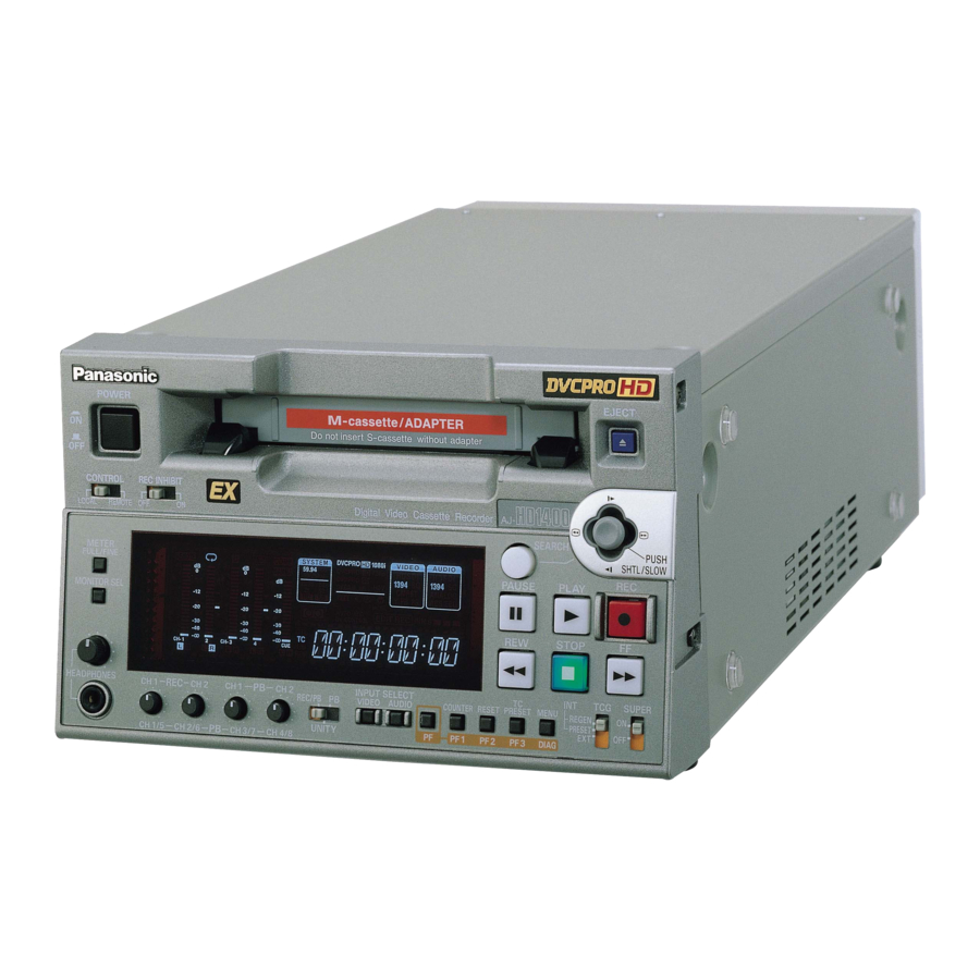
Summary of Contents for Panasonic AJ-HD1400E
-
Page 1: Operating Instructions
Operating Instructions Digital HD Video Cassette Recorder Model No. Before operating this product, please read the instructions carefully and save this manual for future use. ENGLISH F0606T1086 -F Printed in Japan VQT0X83-1... -
Page 2: Read This First
Read this first! For AJ-HD1400P and AJ-HD1400E _THIS APPARATUS MUST BE GROUNDED To ensure safe operation the three-pin plug must be inserted only into a standard three-pin power outlet which is effectively grounded through normal house- hold wiring. Extension cords used with the equipment must be three-core and be correctly wired to provide connec- tion to the ground. - Page 3 CAUTION: Operation at a voltage other than 120 V AC may require the use of a different AC plug. Please contact either a local or foreign Panasonic authorized service center for assistance in selecting an alternate AC plug. protection...
- Page 4 Read this first! (continued) For AJ-HD1400E Caution for AC Mains Lead FOR YOUR SAFETY PLEASE READ THE FOLLOWING TEXT CAREFULLY. This product is equipped with 2 types of AC mains cable. One is for continental Europe, etc. and the other one is only for U.K.
-
Page 5: Table Of Contents
Contents Read this first! ... 2 Introduction... 6 Features... 6 Parts and their functions ... 9 Front panel (1) ...9 Front panel (2) ...10 Front panel (3) ...11 Display panel ...12 Rear panel ...14 Reference signals... 16 Reference frequencies ... 17 Tapes ... -
Page 6: Introduction
Introduction This unit is a multi-format VTR capable of recording and playing back HD signals (1080i/59.94 Hz, 1080i/50 Hz, 720P/59.94 Hz, 720P/50 Hz) in DVCPRO HD-LP format using a small cassette tape 1/4 inch wide, HD (DVCPRO HD/DVCPRO HD-LP*) and SD (DVCPRO50/DVCPRO) recorded in DVCPRO format as well as conventional consumer DV/DVCAM tapes. - Page 7 Features (continued) Cross-convert function The unit comes with a built-in cross-converter to enable 1080i/59.94 Hz format signals to be converted into 720p/59.94 Hz format signals or, conversely, to enable 720p/59.94 Hz format signals to be converted into 1080i/59.94 Hz format signals. Cross-convert with 1080i/50 Hz and 720p/50 Hz is also possible.
- Page 8 Features (continued) Multi-functional interfaces Serial digital input/output The unit’s HD component serial I/O interface enables interfacing with HD component video signals and 8- channel digital audio signals using a single BNC connector. (SMPTE 292M/296M/299M) The unit is also equipped with an SD downconverter as a standard feature so that SD component serial signals can be output as well.
-
Page 9: Parts And Their Functions
FINE mode: The scale in 0.5 dB increments is selected. The position indicates the standard level of –20 dB (For AJ-HD1400P) or –18 dB (For AJ-HD1400E). (See page 12) MONITOR SEL button This button is used to select the audio signals which are to be output to the AUDIO MON L and R connectors. -
Page 10: Front Panel (2)
Parts and their functions Front panel (2) REC/PB CH1/5 CH2/6 CH3/7 CH4/8 INPUT SELECT buttons These buttons are used to switch the video and audio input signals. They can also be used to switch the video input signals to the internal reference signal selected as the menu item No.601 VIDEO INT SG setting. -
Page 11: Front Panel (3)
Parts and their functions Front panel (3) REC/PB CH1/5 CH2/6 CH3/7 CH4/8 Audio level control knobs These knobs are used to adjust the recording and playback level of the PCM audio signals. The audio level control selector switch between the recording/playback level adjustment for CH1/CH2 and the playback level adjustment for CH1 to CH4. -
Page 12: Display Panel
The audio level display is switched between the FULL mode and FINE mode using the METER selector button (See page 9). Reference level (–20dB: AJ-HD1400P) (–18dB: AJ-HD1400E) FULL mode FINE mode FULL mode REMOTE lamp This lamp lights when the CONTROL switch has been set to the REMOTE position. - Page 13 Parts and their functions lamp This lamp lights when a cassette tape is inserted into the VTR. In the standby OFF mode, this lamp is flashing. nter display The tape counter, time code, etc. are displayed here. The type of value displayed is indicated by CTL, TC, UB or REM.
-
Page 14: Rear Panel
The DC power cable is packed together with the AJ- A95. Fuse holder This holds the AC 250 V/2.5 A fuse (time lag type). <Note> Use the fuse specified by Panasonic. AC IN DC OUT 12V 250mA FUSE 250V T2.5AH... - Page 15 Parts and their functions VIDEO OUT (1, 2, Y, P ) connectors By changing the menu item No.615 V OUT SEL setting, either analog composite signals or HD component Y signals are output from the VIDEO OUT1 connector. Analog composite signals with superimposed information embedded can be output from the VIDEO OUT2 connector.
-
Page 16: Reference Signals
Parts and their functions IEEE1394 digital input/output connector This unit is capable of input and output through a digital interface conforming to the IEEE1394 standard. Use 6- pin connectors. Does not support bus power. Reference signals During tape playback, the video output reference signals are as shown in the table below. In the 59.94 Hz/60 Hz or 50 Hz mode Input signals REF_IN... -
Page 17: Reference Frequencies
Reference frequencies During tape playback, the video output reference frequencies are as shown in the table below. In the 59.94 Hz/60 Hz or 60 Hz mode Input signals REF_IN INPUT AUTO Complies with Input HD REF IN frequency HD_REF_IN Complies with Not input HD REF IN frequency... -
Page 18: Tapes
When consumer-use DV and DVCAM cassette tapes are used, the maximum time for STILL TIMER is set to 10 seconds. It is recommended that tapes bearing the Panasonic brand be used as the consumer-use DV tapes. CH1/5 CH2/6 CH3/7... -
Page 19: Connections
Connections Example of connections with an editing controller AV monitor Analog composite signals Audio monitor signals Editing controller AG-A850 etc. To REMOTE CONTROL connector Source unit AV monitor <Notes> When disconnecting the remote signals (9P) from one component and re-connecting them to another component, check the settings,etc. -
Page 20: Ieee1394 Digital Interface
IEEE1394 digital interface Settings for this unit Confirm that menu No. 882 DIF IN CH and No. 883 DIF OUT CH of this unit are set to “AUTO.” Input-output of the digital input signal is enabled when “59/ 60” is selected in menu No. 25 SYSTEM FREQ and operated in 59.94 Hz. -
Page 21: Vanc Data Recording/Playback
VANC data recording/playback VANC data recording Detects the VANC data packets that multiplex recorded in the following range of the Y stream of HD SDI. 1080i: L9–L20, L571–L583 720P: L9–L25 <Note> HANC data packets are not be detected. Records VANC data packets up to the following volume in the VAUX region of the DVCPRO HD format in the order of the earlier line. -
Page 22: Joystick And Variable Speed Playback
Joystick and Variable Speed Playback Joystick REC/PB CH1/5 CH2/6 CH3/7 CH4/8 Press the SEARCH button to activate the joystick. When “STICK” has been selected as the menu item No.100 SEARCH ENA setting, the joystick will be activated without pressing the SEARCH button. Press the joystick to switch between the SHTL mode and SLOW mode. -
Page 23: Pf (Programmable Function)
662 V LEVEL 25 SYSTEM FERQ 663 C LEVEL 26 HD SYS H ADV (AJ-HD1400P) C PHASE 181 TYPE A NEAR (AJ-HD1400E) SETUP LVL 182 TYPE A END (AJ-HD1400P) BK LVL 183 TYPE B NEAR (AJ-HD1400E) 184 TYPE B END... -
Page 24: Pause/Recording (Recording With Pauses)
Pause/Recording (Recording with pauses) Press the PAUSE button during playback of the cassette tape. Press the REC button to move to the REC PAUSE mode. When menu item No. 154 AUTO BACK is set to “REC-P” or “ALL,” the tape is rewound for a few seconds from the position where the PAUSE button is pressed. -
Page 25: Repeat Playback
Repeat playback Setting the BEGIN and END points Press the MENU button. Select menu item No. 161 CTL (TC) BGN or No. 162 END, and tilt the joystick right/left while pressing the SEARCH button. By operating the joystick, the user can choose whether or not to set the BEGIN and END points. -
Page 26: Recording From A Variable Frame Rate Camera
Recording from a variable frame rate camera Recording the HD SDI output signal from a variable frame rate camera Connect the HD SDI (720/30Pover 59.94P) output of the variable frame rate camera to the HD SDI input connector of this unit. Select “SLTC”... -
Page 27: Setup (Initial Settings)
Setup (initial settings) This unit’s main settings can be performed and checked using the on-screen menus which are displayed on the video monitor connected to the unit. It is also possible to set and confirm using the item number and the setting number or the item name, which are displayed on the display part on the front panel. -
Page 28: Setting The User Defaults
Setup (initial settings) Incline the joystick up and down to adjust the cursor in the default settings screen to the “LOAD” position and press the joystick. The mode for this unit changes to the LOAD mode, the LOAD screen is displayed on the video monitor, and the item name is displayed in the counter display. -
Page 29: User Default Loading Method
Setup (initial settings) Confirmation screen for SAVE is displayed. When the PLAY button is pressed, the set value is stored and the display returns to the menu screen. When the STOP button is pressed, the display returns to the menu screen without storing the set value. SET-UP MENU <SAVE>... -
Page 30: Menu Protection Method
Setup (initial settings) Menu protection method By switching to the menu protect mode, it is possible to disable the setup menu even if the MENU button on the front panel is pressed. Press the MENU button. A select screen for the major menu items is displayed on the video monitor, and the names are displayed in the counter display. -
Page 31: System Frequency Switching
Setup (initial settings) System frequency switching <Selection of the record and playback format and the synchronizing signal depends on the operation mode> NO.25 SYSTEM Recordable format FERQ 1080/59.94i (HD_LP) 720/59.94p (HD_LP) 59/60 720/60.00p (HD_LP) (Only the variable frame rate signal can be recorded.) 1080/50i (HD_LP) 50i/25P 720/50p (HD_LP) -
Page 32: Setup Menus
Setup menus Menus which are displayed The menus displayed differ depending on the setting selected for menu item No.25 SYSTEM FREQ. Item 05 ENCODER SEL 06 V LEVEL CTRL 12 SYS H (HD) 14 SYS SC (SD) 15 VO SYS H (SD) 16 SD SYS H (SD) 18 SCH COAR (SD) 19 SCH FINE (SD) - Page 33 Setup menus (continued) Item 184 TYPE-B END 190 V IN SEL INH 191 A IN SEL INH 202 ID SEL 302 CONFI EDIT 303 AUD EDIT IN 304 AUD EDIT OUT 307 AFTER CUE-UP 320 EDIT RPLCE1 321 EDIT RPLCE2 322 EDIT RPLCE3 323 EDIT RPLCE4 324 EDIT RPLCEC...
- Page 34 Setup menus (continued) Item 661 BK LVL (SD) 662 V LEVEL 663 C LEVEL 664 HUE 665 SETUP LVL 676 BLK CLIP 680 CC (F1) BLANK 681 CC (F2) BLANK 682 VO SETUP (HD) (For AJ-HD1400P) 683 VO SETUP (SD) (For AJ-HD1400P) 684 EDH (SD) 685 ESR MODE (SD) 686 CCR MODE (SD)
- Page 35 <Notes> AJ-HD1400 Use the MT-200/2000 (manufactured by Musashi and External encoder recommended by Panasonic) as the external encoder remote controller/ remote controller. However, its VIDEO PHASE, SYNC AJ-HD1400 PHASE and SC PHASE controls will not work. During menu operations and operations using the PF function, operations from the external encoder remote controller cannot be accepted.
-
Page 36: System
Setup menus (continued) SYSTEM No./Item Description of setting For setting whether to perform the various adjustments for the video output signals using this ENCODER VTR or using an external encoder remote controller. 0001 LOCAL : The various adjustments for the video output signals are performed using this VTR. -
Page 37: Basic
Setup menus (continued) SYSTEM (continued) No./Item Description of setting For selecting the system frequency. For details, refer to “Procedure for shifting the system SYSTEM frequency" (page 31). FREQ 0000 59/60 : The 59.94 Hz or 60 Hz system frequency is selected. - Page 38 Setup menus (continued) BASIC (continued) No./Item Description of setting For setting what the information to be superimposed. 0000 TIME : DISPLAY Only the data is displayed. (“Data” refers to the CTL, TC or UB value selected by the COUNTER button.) 0001 T&STA : The data and operation status are displayed.
-
Page 39: Formats For Playback
Setup menus (continued) BASIC (continued) No./Item Description of setting For setting the field frequency. 030* 0000 59/23 : The field frequency is set to 59.94/23.98 Hz. FREQUENCY 0001 60/24 : The field frequency is set to 60/24 Hz. <Note> The field frequency which is set here takes effect only when there is no input which supports the OUT REF setting. -
Page 40: Operation
Setup menus (continued) OPERATION No./Item Description of setting To set the transition method to search mode (stick operation). SEARCH 0000 STICK : Shift to the search mode when the SEARCH button is pressed or when the stick is operated. 0001 KEY : Do not shift to the search mode unless the SEARCH button is pressed. - Page 41 Setup menus (continued) OPERATION (continued) No./Item Description of setting For setting whether to restrict the operation of the 115* EJECT button on the front panel. EJECT SW 0000 REC : Operation is inhibited while the unit is in the recording mode. 0001 OFF : The EJECT button can be operated in all operation...
- Page 42 Setup menus (continued) OPERATION (continued) No./Item Description of setting For setting whether the recording/stop is executed 155* automatically in conjunction with the Recording Mark AUTO REC of the HD SDI input signals from our camera recorder or not. 0000 OFF : Do not to execute the recording/stop automatically.
-
Page 43: Interface
The DVCPRO ID information is set. 0002 ORIG : Set this only when the unit is connected to a Panasonic controller (such as the AG-A850, optional accessory). <Note> Select 1 (DVCPRO) or 2 (ORIG) if “23/24,” “25(HD),” “25(SD),” “50(HD)” or “50(SD)” is selected as the menu item No.25 SYSTEM FREQ setting. -
Page 44: Edit
Setup menus (continued) EDIT No./Item Description of setting For selecting whether to perform simultaneous 302* playback during editing. CONFI EDIT 0000 OFF : Simultaneous playback is not performed. 0001 ON : Simultaneous playback is performed. For selecting how to connect the digital audio edit IN 303* points. -
Page 45: Tape Protect
Setup menus (continued) TAPE PROTECT No./Item Description of setting For setting the time to be taken before the unit is set in the tape protection mode when it is left standing in STILL TIMER the STOP or STILL status. (Units: S = seconds, min = minutes) 0000 0.5S 0001... - Page 46 Setup menus (continued) TIME CODE (continued) No./Item Description of setting For selecting the editing mode range when the VTR is 506* operating in the REGEN mode while performing REGEN editing operations with “AUTO” selected as the menu MODE item No.503 TCG MODE setting. 0000 AS&IN : Regeneration applies during assemble or insert...
-
Page 47: Video
Setup menus (continued) VIDEO No./Item Description of setting For selecting the type of internal standard signals. 601* 0000 100%CB : VIDEO INT A 100% color bar signal is selected. 0001 75%CB : A 75% color bar signal is selected. 0002 SMPTE : An SMPTE color bar signal is selected. - Page 48 SD SDI output and analog composite output. (Approx. –30 o to +30 o) (AJ-HD1400P) 0000 C PHASE 0062 (AJ-HD1400E) 0124 <Notes> to 0 dB to +3 dB) to 0 dB to +3 dB) *1 Displayed menus may vary depending on the settings in menu No.
- Page 49 (–10 o to +10 o) (AJ-HD1400P) –10% BK LVL 0.0% (AJ-HD1400E) +10.0% <Note> This setting takes effect when “CMPST” has been selected as the menu item No.650 setting. For setting whether to clip what is below the pedestal...
- Page 50 Setup menus (continued) VIDEO (continued) No./Item Description of setting This sets the line on which the UMID information is to 692* be superimposed. UMID POS 0000 BLANK 0001 0006 0008 <Notes> The line selected for the menu item No. 501 VITC POS-1 and No.
-
Page 51: Audio
Setup menus (continued) AUDIO No./Item Description of setting For setting the reference level of the analog audio 701* input (CH1). CH1 IN LV 0000 0001 0002 –20dB 0003 –60dB For setting the reference level of the analog audio 702* input (CH2). CH2 IN LV 0000 0001... - Page 52 Setup menus (continued) AUDIO (continued) No./Item Description of setting For selecting the channel for the signal output to the analog audio output terminal CH1/CH2. ANA CH1/2 0000 CH1/2 0001 CH3/4 0002 CH5/6 0003 CH7/8 For selecting the audio output level during DV format 759* playback.
-
Page 53: Dif
Setup menus (continued) No./Item Description of setting For setting the transfer speed of the IEEE1394 digital 880* interface output. DIF SPEED 0000 S100 : 100 Mbps 0001 S200 : 200 Mbps 0002 S400 : 400 Mbps <Note> When S100 has been selected as this item’s setting, DVCPRO HD format signals cannot be input or output. -
Page 54: Menu
Setup menus (continued) MENU No./Item Description of setting The unit starts with the selected user default loaded when the power is turned on. P.ON LOAD 0000 OFF : The unit starts with the previous set values. 0001 USER1 : The unit starts with the selected user 1 loaded. 0002 USER2 : The unit starts with the selected user 2 loaded. -
Page 55: Time Code/User Bits
Time code/user bits Time code The time code is used when the time code signal generated by the time code generator (time code signal generator) is to be recorded on the tape, its values are to be read by the time code reader (time code signal reader), and the absolute position of the tape is to be displayed in increments of hours, minutes, seconds and frames. -
Page 56: Timecodes Recorded By This Product
Time code/user bits Time code when power is not supplied Even if the power is not supplied, the time code generator operates for many hours (about 1 year) by using the backup feature. And the accuracy when power is not supplied is about ±30 seconds a month. -
Page 57: Superimpose Screen
Superimpose screen The control signals, time code, etc. are displayed using abbreviations. TV monitor TCR ¢¢ : ¢¢ : ¢¢ : ¢¢ Abbreviations: CTL : Control signal count value TCR : Time code data recorded in the SBC area TCR.: Time code data recorded in the VAUX area UBR : User bit data recorded in the SBC area UBR.: User bit data recorded in the VAUX area TCG : Time code data of the time code generator... -
Page 58: Video Head Cleaning
Video head cleaning This unit is equipped with an auto head cleaning function which automatically reduces the amount of dirt on the video heads. However, in order to maximize the unit’s reliability, it is recommended that the video heads be cleaned as and when appropriate. -
Page 59: Error Messages
Error messages CH1/5 CH2/6 CH3/7 CH4/8 When a warning occurs in this unit, the error number is indicated on the counter display. Open the DIAG menu to display a description of the error on the counter display or monitor TV. When a operational malfunction has occurred in the unit, the error number flashes on the counter display. -
Page 60: Umid Information Display
Error messages (continued) If “T&S&M” is selected in the menu No. 008 DISPLAY SEL, a message appears in the modedisplay whenever a warning or error occurs. When multiple events occur, the event with the highest priority is displayed. Priority Display Error messages (See error message table) High... -
Page 61: Warning Messages
Error messages (continued) Displaying the warning information A warning message appears when a warning has occurred. “NO WARNING” appears when a warning has not occurred. When more than one warning has occurred simultaneously, move the joystick up or down to check the description of each warning. -
Page 62: Error Messages
Error messages (continued) Warning messages (continued) Priority Monitor display Description E-00 This appears when the servo is not locked for three or (SERVO NOT more seconds during playback or recording. LOCKED) (In 23.98/24 Hz mode) Display when the time code is recorded in DF mode. On the drop point of the time code, the video output is E-93 garbled and audio output is muted. - Page 63 Error messages (continued) Error messages (continued) Monitor display E-55 If the tape has not been taken up during unloading, this error number flashes on the display. UNLOAD ERROR E-57 If the start or end processing operation is not completed, this error S-FF/REW number flashes on the display.
-
Page 64: Emergency Eject
Emergency eject Procedure to ejecting the tape manually in an emergency If the cassette tape fails to be ejected even when the EJECT button is pressed, it can be ejected as follows. Follow the steps below after making absolutely sure that the unit’s power has been turned off. Remove the top panel. -
Page 65: Specifications
Specifications [GENERAL] Power supply: AC 100-240 V , 50/60 Hz, 85 W DC 12 V, 5.3 A, 64 W indicates safety information. Ambient operating temperature: 5°C to 40°C (41°F to 104°F) Storage temperature: –20°C to 60°C (–4°F to 140°F) Ambient operating humidity: 10% to 80% (no condensation) Dimensions (WkHkD): 214 mm k 132 mm k 442 mm... - Page 66 Less than –80 dB (1 kHz, between 2 channels) Wow & flutter: Below measurable limits Headroom: 20 dB (For AJ-HD1400P) 18 dB (For AJ-HD1400E) _Audio input connectors Analog input (CH1, CH2): XLR k2, 600 h/high impedance switchable +4/0/–20 dBu/–60 dBu switchable...
- Page 67 Compliant with IEEE1394-1995 Compliant with IEC 61883-Part1, Part2 Control command: Compliant with AV/C command set [Accessories] Power supply cord k 1 (AJ-HD1400P) Power supply cord k 2 (AJ-HD1400E) Weight and dimensions shown are approximate. Specifications are subject to change without notice.
- Page 68 PANASONIC BROADCAST & TELEVISION SYSTEMS COMPANY UNIT COMPANY OF PANASONIC CORPORATION OF NORTH AMERICA Executive Office: One Panasonic Way 4E-7, Secaucus, NJ 07094 (201) 348-7000 EASTERN ZONE: One Panasonic Way 4E-7, Secaucus, NJ 07094 (201) 348-7196 Southeast Region: (201) 348-7162 WESTERN ZONE: 3330 Cahuenga Blvd W., Los Angeles, CA 90068 (323) 436-3500...