Table of Contents
Advertisement
Quick Links
.
Sec. 1
Service Information
Sec. 2
Disassembly Procedures
Sec. 3
Mechanical Adjustment
Sec. 4
Electrical Adjustment
Sec. 5
Block Diagrams
Sec. 6
Schematic Diagrams
Sec. 7
Major Part Location
Sec. 8
Exploded Views &
Replacement Parts List
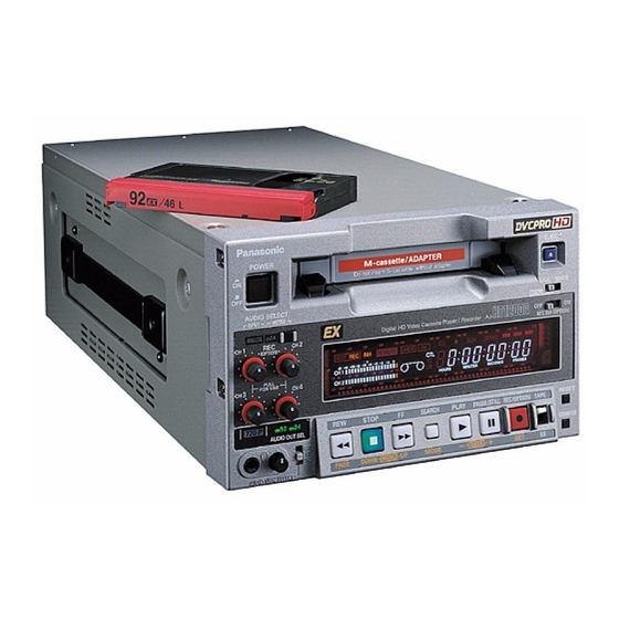
AJ-HD1200A
Digital Video Cassette Player/Recorder
AJ-HD1200AP/E/MC
HD-SDI In/Out and SD-SDI Out Board
AJ-YAD120AG
© 2004 Matsushita Electric Industrial Co., Ltd. All rights reserved.
Unauthorized copying and distribution is a violation of law.
ORDER NO. BSD04050100
D26
AJ-YA120AG
Digital Video In/Out Board
AJ-YA120A
AJ-YAD120A
Advertisement
Chapters
Table of Contents

Related Manuals for Panasonic DVCPRO HD EX AJ-HD1200AP


Summary of Contents for Panasonic DVCPRO HD EX AJ-HD1200AP
- Page 1 ORDER NO. BSD04050100 Sec. 1 Service Information Sec. 2 Disassembly Procedures Sec. 3 Mechanical Adjustment Digital Video Cassette Player/Recorder Sec. 4 Electrical Adjustment AJ-HD1200AP/E/MC Sec. 5 Block Diagrams Sec. 6 Schematic Diagrams HD-SDI In/Out and SD-SDI Out Board Sec. 7 Major Part Location AJ-YA120AG Sec.
- Page 2 WARNING This service information is designed for experienced repair technicians only and is not designed for use by the general public. It does not contain warnings or cautions to advise non-technical individuals of potential dangers in attempting to service a product. Products powered by electricity should be serviced or repaired only by experienced professional technicians.
- Page 3 - 3 -...
- Page 4 AJ-HD1200AE - 4 -...
- Page 5 - 5 -...
- Page 6 AJ-YA120AG AJ-YAD120AG - 6 -...
- Page 7 SAFETY PRECAUTIONS GENERAL GUIDELINES ELECTROSTATICALLY SENSITIVE (ES) DEVICES 1. When servicing, observe the original lead dress. If a Some semiconductor (solid state) devices can be damaged short circuit is found, replace all parts, which have been easily by static electricity. Such components commonly are over-heated or damaged by the short circuit.
- Page 8 AJ-HD1200AP - 8 -...
- Page 9 - 9 -...
- Page 10 AJ-HD1200AE - 10 -...
- Page 11 - 11 -...
- Page 12 AJ-YA120AG AJ-YAD120AG - 12 -...
- Page 13 FCD0405NTKK67E494E495...
- Page 14 COMPONENT VOUT SYS 01/8 NAME CIRCUIT BOARD NO. DRAWING NO. KR 3A0187(1/8) VEP83625B SCM039...
- Page 15 COMPONENT VOUT SYS 02/8 NAME CIRCUIT BOARD NO. DRAWING NO. KR 3A0187(2/8) VEP83625B SCM040...
- Page 16 COMPONENT VOUT SYS 03/8 NAME CIRCUIT BOARD NO. DRAWING NO. KR 3A0187(3/8) VEP83625B SCM041...
- Page 17 COMPONENT VOUT SYS 04/8 NAME CIRCUIT BOARD NO. DRAWING NO. KR 3A0187(4/8) VEP83625B SCM042...
- Page 18 COMPONENT VOUT SYS 05/8 NAME CIRCUIT BOARD NO. DRAWING NO. KR 3A0187(5/8) VEP83625B SCM043...
- Page 19 COMPONENT VOUT SYS 06/8 NAME CIRCUIT BOARD NO. DRAWING NO. KR 3A0187(6/8) VEP83625B SCM044...
- Page 20 COMPONENT VOUT SYS 07/8 NAME CIRCUIT BOARD NO. DRAWING NO. KR 3A0187(7/8) VEP83625B SCM045...
- Page 21 COMPONENT VOUT SYS 08/8 NAME CIRCUIT BOARD NO. DRAWING NO. KR 3A0187(8/8) VEP83625B SCM046...
- Page 22 COMPONENT V_JACK NAME CIRCUIT BOARD NO. DRAWING NO. KR 3A0010(1/1) VEP83626A SCM102...
- Page 23 COMPONENT HD_SDI_RX(PLD) 01/03 NAME CIRCUIT BOARD NO. DRAWING NO. KR 3A0028(1/3) VEP83631A SCM133...
- Page 24 COMPONENT HD_SDI_RX(EQ,S/P) 02/03 NAME CIRCUIT BOARD NO. DRAWING NO. KR 3A0028(2/3) VEP83631A SCM134...
- Page 25 COMPONENT HD_SDI_RX(DEC) 03/03 NAME CIRCUIT BOARD NO. DRAWING NO. KR 3A0028(3/3) VEP83631A SCM135...
- Page 26 COMPONENT HD_SDI_TX(ENC/PLD) 01/02 NAME CIRCUIT BOARD NO. DRAWING NO. KR 3A0029(1/2) VEP83632A SCM136...
- Page 27 COMPONENT HD_SDI_TX(P/S,DRV) 02/02 NAME CIRCUIT BOARD NO. DRAWING NO. KR 3A0029(2/2) VEP83632A SCM137...
- Page 28 COMPONENT CONNECTOR NAME CIRCUIT BOARD NO. DRAWING NO. KR 3A0032(1/8) VEP83634A SCM125...
- Page 29 COMPONENT SYNC_SEP NAME CIRCUIT BOARD NO. DRAWING NO. KR 3A0032(2/8) VEP83634A SCM126...
- Page 30 COMPONENT 4FSC_SGEN NAME CIRCUIT BOARD NO. DRAWING NO. KR 3A0032(3/8) VEP83634A SCM127...
- Page 31 COMPONENT 4FSC_PLL NAME CIRCUIT BOARD NO. DRAWING NO. KR 3A0032(4/8) VEP83634A SCM128...
- Page 32 COMPONENT HD_PLL NAME CIRCUIT BOARD NO. DRAWING NO. KR 3A0032(5/8) VEP83634A SCM129...
- Page 33 COMPONENT SD_PLL NAME CIRCUIT BOARD NO. DRAWING NO. KR 3A0032(6/8) VEP83634A SCM130...
- Page 34 COMPONENT HD_SDI_RX&PROC NAME CIRCUIT BOARD NO. DRAWING NO. KR 3A0032(7/8) VEP83634A SCM131...
- Page 35 COMPONENT SDI_TX NAME CIRCUIT BOARD NO. DRAWING NO. KR 3A0032(8/8) VEP83634A SCM132...
- Page 36 COMPONENT 1394_JACK NAME CIRCUIT BOARD NO. DRAWING NO. KR 3A0148(1/1) VEP83644A SCM117...
- Page 37 COMPONENT 1394 IF 01/12 NAME CIRCUIT BOARD NO. DRAWING NO. KR 3A0181(1/12) VEP83651A SCM105...
- Page 38 COMPONENT 1394 IF 02/12 NAME CIRCUIT BOARD NO. DRAWING NO. KR 3A0181(2/12) VEP83651A SCM106...
- Page 39 COMPONENT 1394 IF 03/12 NAME CIRCUIT BOARD NO. DRAWING NO. KR 3A0181(3/12) VEP83651A SCM107...
- Page 40 COMPONENT 1394 IF 04/12 NAME CIRCUIT BOARD NO. DRAWING NO. KR 3A0181(4/12) VEP83651A SCM108...
- Page 41 COMPONENT 1394 IF 05/12 NAME CIRCUIT BOARD NO. DRAWING NO. KR 3A0181(5/12) VEP83651A SCM109...
- Page 42 COMPONENT 1394 IF 06/12 NAME CIRCUIT BOARD NO. DRAWING NO. KR 3A0181(6/12) VEP83651A SCM110...
- Page 43 COMPONENT 1394 IF 07/12 NAME CIRCUIT BOARD NO. DRAWING NO. KR 3A0181(7/12) VEP83651A SCM111...
- Page 44 COMPONENT 1394 IF 08/12 NAME CIRCUIT BOARD NO. DRAWING NO. KR 3A0181(8/12) VEP83651A SCM112...
- Page 45 COMPONENT 1394 IF 09/12 NAME CIRCUIT BOARD NO. DRAWING NO. KR 3A0181(9/12) VEP83651A SCM113...
- Page 46 COMPONENT 1394 IF 10/12 NAME CIRCUIT BOARD NO. DRAWING NO. KR 3A0181(10/12) VEP83651A SCM114...
- Page 47 COMPONENT 1394 IF 11/12 NAME CIRCUIT BOARD NO. DRAWING NO. KR 3A0181(11/12) VEP83651A SCM115...
- Page 48 COMPONENT 1394 IF 12/12 NAME CIRCUIT BOARD NO. DRAWING NO. KR 3A0181(12/12) VEP83651A SCM116...
- Page 49 COMPONENT A_I/O(CONNECTOR) 01/05 NAME CIRCUIT BOARD NO. DRAWING NO. KR 4A0021(1/5) VEP84368B SCM059...
- Page 50 COMPONENT A_I/O(OUTPUT12) 02/05 NAME CIRCUIT BOARD NO. DRAWING NO. KR 4A0021(2/5) VEP84368B SCM060...
- Page 51 COMPONENT A_I/O(OUTPUT34) 03/05 NAME CIRCUIT BOARD NO. DRAWING NO. KR 4A0021(3/5) VEP84368B SCM061...
- Page 52 COMPONENT A_I/O(INPUT12) 04/05 NAME CIRCUIT BOARD NO. DRAWING NO. KR 4A0021(4/5) VEP84368B SCM062...
- Page 53 COMPONENT A_I/O(INPUT34) 05/05 NAME CIRCUIT BOARD NO. DRAWING NO. KR 4A0021(5/5) VEP84368B SCM063...
- Page 54 COMPONENT APROC 01/9 NAME CIRCUIT BOARD NO. DRAWING NO. KR 4A0089(1/9) VEP84393B SCM018...
- Page 55 COMPONENT APROC 02/9 NAME CIRCUIT BOARD NO. DRAWING NO. KR 4A0089(2/9) VEP84393B SCM019...
- Page 56 COMPONENT APROC 03/9 NAME CIRCUIT BOARD NO. DRAWING NO. KR 4A0089(3/9) VEP84393B SCM020...
- Page 57 COMPONENT APROC 04/9 NAME CIRCUIT BOARD NO. DRAWING NO. KR 4A0089(4/9) VEP84393B SCM021...
- Page 58 COMPONENT APROC 05/9 NAME CIRCUIT BOARD NO. DRAWING NO. KR 4A0089(5/9) VEP84393B SCM022...
- Page 59 COMPONENT APROC 06/9 NAME CIRCUIT BOARD NO. DRAWING NO. KR 4A0089(6/9) VEP84393B SCM023...
- Page 60 COMPONENT APROC 07/9 NAME CIRCUIT BOARD NO. DRAWING NO. KR 4A0089(7/9) VEP84393B SCM024...
- Page 61 COMPONENT APROC 08/9 NAME CIRCUIT BOARD NO. DRAWING NO. KR 4A0089(8/9) VEP84393B SCM025...
- Page 62 COMPONENT APROC 09/9 NAME CIRCUIT BOARD NO. DRAWING NO. KR 4A0089(9/9) VEP84393B SCM026...
- Page 63 COMPONENT A_JACK NAME CIRCUIT BOARD NO. DRAWING NO. KR 4A0004(1/1) VEP84394A SCM103...
- Page 64 COMPONENT RF/EQ 01/14 NAME CIRCUIT BOARD NO. DRAWING NO. KR 5A0014(1/14) VEP85214B SCM004...
- Page 65 COMPONENT RF/EQ 02/14 NAME CIRCUIT BOARD NO. DRAWING NO. KR 5A0014(2/14) VEP85214B SCM005...
- Page 66 COMPONENT RF/EQ 03/14 NAME CIRCUIT BOARD NO. DRAWING NO. KR 5A0014(3/14) VEP85214B SCM006...
- Page 67 COMPONENT RF/EQ 04/14 NAME CIRCUIT BOARD NO. DRAWING NO. KR 5A0014(4/14) VEP85214B SCM007...
- Page 68 COMPONENT RF/EQ 05/14 NAME CIRCUIT BOARD NO. DRAWING NO. KR 5A0014(5/14) VEP85214B SCM008...
- Page 69 COMPONENT RF/EQ 06/14 NAME CIRCUIT BOARD NO. DRAWING NO. KR 5A0014(6/14) VEP85214B SCM009...
- Page 70 COMPONENT RF/EQ 07/14 NAME CIRCUIT BOARD NO. DRAWING NO. KR 5A0014(7/14) VEP85214B SCM010...
- Page 71 COMPONENT RF/EQ 08/14 NAME CIRCUIT BOARD NO. DRAWING NO. KR 5A0014(8/14) VEP85214B SCM011...
- Page 72 COMPONENT RF/EQ 09/14 NAME CIRCUIT BOARD NO. DRAWING NO. KR 5A0014(9/14) VEP85214B SCM012...
- Page 73 COMPONENT RF/EQ 10/14 NAME CIRCUIT BOARD NO. DRAWING NO. KR 5A0014(10/14) VEP85214B SCM013...
- Page 74 COMPONENT RF/EQ 11/14 NAME CIRCUIT BOARD NO. DRAWING NO. KR 5A0014(11/14) VEP85214B SCM014...
- Page 75 COMPONENT RF/EQ 12/14 NAME CIRCUIT BOARD NO. DRAWING NO. KR 5A0014(12/14) VEP85214B SCM015...
- Page 76 COMPONENT RF/EQ 13/14 NAME CIRCUIT BOARD NO. DRAWING NO. KR 5A0014(13/14) VEP85214B SCM016...
- Page 77 COMPONENT RF/EQ 14/14 NAME CIRCUIT BOARD NO. DRAWING NO. KR 5A0014(14/14) VEP85214B SCM017...
- Page 78 COMPONENT RF/CUE 1/11 NAME CIRCUIT BOARD NO. DRAWING NO. KR 5A0002(1/11) VEP85215A SCM047...
- Page 79 COMPONENT RF/CUE 2/11 NAME CIRCUIT BOARD NO. DRAWING NO. KR 5A0002(2/11) VEP85215A SCM048...
- Page 80 COMPONENT RF/CUE 3/11 NAME CIRCUIT BOARD NO. DRAWING NO. KR 5A0002(3/11) VEP85215A SCM049...
- Page 81 COMPONENT RF/CUE 4/11 NAME CIRCUIT BOARD NO. DRAWING NO. KR 5A0002(4/11) VEP85215A SCM050...
- Page 82 COMPONENT RF/CUE 5/11 NAME CIRCUIT BOARD NO. DRAWING NO. KR 5A0002(5/11) VEP85215A SCM051...
- Page 83 COMPONENT RF/CUE 6/11 NAME CIRCUIT BOARD NO. DRAWING NO. KR 5A0002(6/11) VEP85215A SCM052...
- Page 84 COMPONENT RF/CUE 7/11 NAME CIRCUIT BOARD NO. DRAWING NO. KR 5A0002(7/11) VEP85215A SCM053...
- Page 85 COMPONENT RF/CUE 8/11 NAME CIRCUIT BOARD NO. DRAWING NO. KR 5A0002(8/11) VEP85215A SCM054...
- Page 86 COMPONENT RF/CUE 9/11 NAME CIRCUIT BOARD NO. DRAWING NO. KR 5A0002(9/11) VEP85215A SCM055...
- Page 87 COMPONENT RF/CUE 10/11 NAME CIRCUIT BOARD NO. DRAWING NO. KR 5A0002(10/11) VEP85215A SCM056...
- Page 88 COMPONENT RF/CUE 11/11 NAME CIRCUIT BOARD NO. DRAWING NO. KR 5A0002(11/11) VEP85215A SCM057...
- Page 89 COMPONENT RFEQ_SUB 01/01 NAME CIRCUIT BOARD NO. DRAWING NO. KR 5A0011(1/1) VEP85218A SCM058...
- Page 90 COMPONENT PB VR 01/01 NAME CIRCUIT BOARD NO. DRAWING NO. (1/1) VEP86283A SCM101...
- Page 91 COMPONENT FRONT CONNECT 01/1 NAME CIRCUIT BOARD NO. DRAWING NO. KR 6A0118(1/1) VEP86336A SCM104...
- Page 92 COMPONENT FRONT 01/3 NAME CIRCUIT BOARD NO. DRAWING NO. KR 6A0116(1/3) VEP86343A SCM076...
- Page 93 COMPONENT FRONT 02/3 NAME CIRCUIT BOARD NO. DRAWING NO. KR 6A0116(2/3) VEP86343A SCM077...
- Page 94 COMPONENT FRONT 03/3 NAME CIRCUIT BOARD NO. DRAWING NO. KR 6A0116(3/3) VEP86343A SCM078...
- Page 95 COMPONENT FRONT KEY 01/1 NAME CIRCUIT BOARD NO. DRAWING NO. KR 6A0117(1/1) VEP86344A SCM079...
- Page 96 COMPONENT MAIN 01/1 NAME CIRCUIT BOARD NO. DRAWING NO. KR 6A0119(1/1) VEP86346A SCM100...
- Page 97 INTERCONNECTION AJ-YA120AG V JACK P250 1394 IF V JACK SUB VEP83631A FAN MOTOR VEP83651A VEP83644A P500 100P DC OUT 100P AJ-YAD120AG 100P P600 VEP83632A P1204 P1205 F5:SGEN/SDI VEP83634A POWER 2 160P 100P P1203 VEP81219B 100P P700 100P P1201 P1202 P700 P701 P4002 P651...
- Page 98 OVERALL BLOCK DIAGRAM SDI (AJ-YA120AG) REC PB SDRAM SDRAM SDRAM MICROPROCESSOR VIDEO CHANNEL HD SDI IN AUDIO CHANNEL ROUNDING LINK REC/EE DEC. (W/AUDIO) LINK TIMING (TX) A BUS AUDIO INT SG COMP ACTIVE THRU REC/EE CHANNEL PREPRO LINK B BUS HD PB (RX) HD SDI OUT1...
- Page 99 RF BLOCK DIAGRAM RF/CUE CIRCUIT RF/EQ CIRCUIT REC/PB CIRCUIT IC461 Q173 SP L1 IC1201 5, 6 IC462 Q604, 605, C619, 622, 625, L601, 602 TR L12 DATA P/N IC601, 602 A13, A14 A14, A15 SP_TR HA TR L12 HA TR L12 HEAD BUFF A63, A64...
- Page 100 APROC BLOCK DIAGRAM CH1 IN LV CH1 OUT TL VR4401<7> IC4401 VR4201<6> IC4242<8> IC4409<7> IC4632<8> TP4604<8> IC4242 IC4632<8> IC4205, 4211<6> IC4225, 4221<6> IC4229, 4225<6> <7> IC4639<8> Q4201, C4269 <6> IC4412<7> IC4420, 4412<7> P4301 P4001 <6> IC4606<8> IC4618, 4615<8> P4301 CH1 IN LEVEL REC LEVEL LEVEL...
- Page 101 REC PB BLOCK DIAGRAM IC53<2> RECPB AUD CH12, IC300<7> CH34, CH56, CH78 P202 A/B47,48 IC151<3> IC152<3> SGN/SDI A/B48, 49 CIRCUIT SDRAM SDRAM IC450<9> REC L CTRL (0),(1) P201 REC R CTRL (0),(1) (128M) (128M) FE CTRL (0),(1) IC371<8> SDI REC DATA 1-3 IC4<1>...
- Page 102 V OUT BLOCK DIAGRAM P100 P150 IC54<3> UDC CIRCUIT P205 SUB YE (0-9), SDI PB HD DATA1-3 (0, 1)/ (AJ-YA120) HD Y DATA (0-9), C DATA (0-9) SUB Y0 (0-9), BUFF CLK, SDI PB HD H/ FRM A/B42-45, A/B42-45, SGEN/SDI SUB PB (0-9), (LVDS) A/B64...
- Page 103 SYS CONTROL BLOCK DIAGRAM IC611<8> IC500<7> IC619<8> CLK18 IC660<8> FROM REC BUFF CLK18 24,23,22,21,20,19,18,17, PB CIRCUIT 16,9,8,7,6,5,4,3,2,1,48, EXT LTC CLK >> EXTLTCGCK FLASH A[17:0] FROM VOUT CIRCUIT<3> IC601, 606<8> 29,30,31,32,33,34,35,36, P4102 38,39,40,41,42,43,44,45 TC IN TO/FROM PULSE P113 LTCIN DQ[15:0] A I/O SHAPER IC621, 601<8>...
- Page 104 CUE AUDIO BLOCK DIAGRAM TP4101 IC4209 P4001 CUE PB OUT IC4001, L4002, IC4106 BUFF FL4001 C4020, 4021 P4001 VR4002 Q4201, CUE RP + IC4207 BIAS REC EQ FL4101 IC4201 QR4201-2 IC4209 CUE RP TRAP P4001 IC4104 CUE RP - IC4103 CUE DA IN HEAD QR4005,...
- Page 105 SERVO BLOCK DIAGRAM MECHANISM I/F CIRCUIT SERVO CIRCUIT TP104 TP105 IC320 IC350 P415 IC410 P300 P903 IC9, 11,13 T_FG1 M T_FG1 M IC350-44 PULSE FG PROCESS P300 T_FG2 M T_FG2 M IC350-45 SHAPPER & I/O IC502 TRH1-/+, TRH2-/+, TRH3-/+ 15-20 FLASH ROM 14,16,10 F SW...
- Page 106 IEEE1394 I/F (AJ-YAD120AG) BLOCK DIAGRAM P500 <11> JTAG REC PB IEEE1394 I/F CIRCUIT CIRCUIT IP503 <11> IC55 <2> IC502 <11> PROG_B, INIT B, X550, IC557 <12> IC200 <5> CCLK, DONE AK6480AF MB29LV160 (EEPROM) TE7720 (FLASH CONF_STATUS XTAL SDRAM(256M) (FPGA CONFIG) MEMORY) [0-2] 72MHz...
- Page 107 UDC (AJ-YA120AG) BLOCK DIAGRAM IN_HD OUT_HD 27_PROC 74_PROC IC214<2> TP600<6> ASIC needs TRS. (16) IC401<4> (18) ASIC_CLK Buff IC215<2> TP409<4> (18) PROCESS_CLK IC211<2> TP700<7> FROM INCLK3 IC600<6> (L6) IC216<2> VOUT_SYS (16) INCLK1 (18) CIRCUIT VOUT_SYS HALF_CLK TP400<4> TP408<4> 1/2 Div. (V5) TP602 TP601...
- Page 108 SGEN/SDI (AJ-YA120AG) BLOCK DIAGRAM IC508<6> EVR DATA IC200<3> IC502<6> Q100-103 IC506<6> IC103,105<2> EVR CLK IC109<2> IC101<2> REF IN X300<4> EXT_REF P4102 SD REF CLK27 EXT REF 4Fsc_CK EVR LD H BUFF NTSC BUFF SYNC SEPA SEPA 4fsc IC320<4> X501<6> IC613<7> X301<4>...
- Page 109 RF/EQ P.C.BOARD (VEP85214) [F1] Q201 Q202 Q306 Q307 Q406 Q407 Q507 Q557 IC101 Q607 IC102 Q702 IC103 Q732 TP405 TP404 TP101 TP103 TP105 TP2 TP3 TP4 TP5 TP6 TP7 IC104 Q762 IC105 Q802 TP402 TP102 TP104 IC106 Q803 IC107 QR1302 IC203 QR1303 IC206...
- Page 110 APROC P.C.BOARD (VEP84393) [F2] IC4004 P4001 IC4005 P4002 IC4007 IC4058 TG402 TG401 IC4059 Q4604 IC4109 QR4601 IC4110 QR4602 TP157 IC4111 TP602 TP603 IC4112 IC4163 TG4155 IC4167 TG4156 TP153 IC4169 TG4157 IC4170 TG4201 VR404 VR403 VR402 VR401 IC4171 TG4401 REF. No.4000 SERIES IC4172 TG4402 IC4173...
- Page 111 REC PB P.C.BOARD (VEP83624) [F3] IC53 IC100 IC150 IC157 IC158 IC250 IC251 IC300 IC370 IC372 IC373 IC450 IC500 IC556 IC558 IC559 IC560 IC561 IC660 TP302 TP304 P300 P651 TP302 TP304 (COMPONENT SIDE)
- Page 112 V OUT SYS P.C.BOARD (VEP83625) [F4] IC30 Q304 IC31 Q305 TP232 IC33 Q433 IC36 QR500 TP233 IC40 QR501 IC41 QR503 IC42 IC45 IC150 IC230 IC232 IC302 IC306 TP232 VR431 IC307 TP233 VR430 IC310 IC312 IC431 VR300 VR303 VR307 IC500 VR301 VR300 IC504 VR302...
- Page 113 RF/CUE P.C.BOARD (VEP85215) TP4001 TP4102 Q464 VR4104 VR4002 Q501 Q502 TG4005 Q531 TP4004 VR4103 VR4001 Q560 TP4003 Q561 Q580 TP4002 Q581 IC10 Q601 IC11 Q106 Q602 IC12 Q107 Q4201 IC401 Q108 QR601 IC402 Q110 QR602 IC431 Q111 QR4201 IC432 Q112 QR4202 IC461 Q114...
- Page 114 RF/CUE P.C.BOARD (VEP85215) IC101 Q322 IC251 Q324 IC601 Q325 IC602 Q329 IC4001 Q333 IC4105 Q335 IC4107 Q337 IC4206 Q403 IC4209 Q405 IC4301 Q435 VR4302 VR4305 VR4304 IC4302 Q463 IC4303 Q465 VR4301 VR4306 VR4303 IC4309 Q503 IC4310 Q505 Q535 Q4001 Q101 Q4002 Q102 Q4003...
- Page 115 SERVO P.C.BOARD (VEP82249) IC300 QR400 IC301 QR401 IC302 QR402 IC350 QR700 IC400 QR701 IC700 QR702 IC701 QR703 IC900 QR800 IC5001 QR801 IC5002 QR802 TG450 QR803 QR804 P300 QR805 P350 QR806 P900 QR807 TP204 P901 QR808 P902 QR809 TP205 QR810 QR811 TP107 Q450 QR812...
- Page 116 MECHA IF P.C.BOARD (VEP82250) Q100 Q101 IC14 Q102 IC15 Q300 IC18 Q301 IC19 Q500 IC300 Q501 IC301 Q502 IC302 Q703 IC303 Q704 IC304 Q705 IC305 QR100 QR101 QR102 TP700 P300 QR103 P400 QR104 P401 QR105 P402 QR106 P403 QR107 P404 QR108 P405 QR109...
- Page 117 MECHA IF P.C.BOARD (VEP82250) IC306 IC307 IC400 IC401 IC500 IC501 IC502 IC503 IC703 IC2254 Q103 Q104 Q105 Q106 Q107 Q400 Q401 VR400 Q503 VR401 Q504 Q505 Q700 Q701 Q702 QR500 QR501 QR502 QR503 VR400 VR401 (FOIL SIDE)
- Page 118 UDC P.C.BOARD (VEP83573) [F4] IC100 IC101 IC205 IC206 IC208 IC210 IC211 IC212 IC213 IC214 TG107 IC215 IC216 IC217 IC218 IC219 IC340 IC401 REF. No. 3000 SERIES IC500 IC501 IC502 IC503 IC600 IC700 IC701 IC709 IP700 IP701 IP702 P100 P700 P701 TG106 TG106 TG107...
- Page 119 UDC P.C.BOARD (VEP83573) [F4] IC102 TP349 IC200 TP350 IC201 TP351 IC202 TP352 IC203 TP355 IC204 TP356 IC207 TP358 IC209 TP361 IC341 TP363 IC342 TP364 IC400 TP365 IC504 TP369 IC505 TP370 TG104 TP370 TP201 IC506 TP372 TP350 TP349 TP200 TP705 TP401 TP364 IC507 TP373...
- Page 120 SGNE SDI P.C.BOARD (VEP83634) [F5] IC411 IC500 IC502 IC508 IC102 IC600 IC104 IC601 IC105 IC602 IC106 IC603 IC107 IC604 IC108 IC605 IC109 IC606 IC112 IC609 IC114 IC610 IC116 IC613 IC200 IC614 IC300 IC620 IC301 IC623 IC302 IC624 IC303 IC625 IC304 IC700 IC305 IC701...
- Page 121 SGEN SDI P.C.BOARD (VEP83634) [F5] TP100 TP113 IC100 TP114 IC101 TP200 IC103 TP203 IC119 TP205 TP300 IC201 TP300 IC312 TP301 VR305 IC314 TP401 IC316 TP603 TP606 TP606 VR400 VR401 VR304 IC340 TP604 IC503 TP605 IC504 TP606 TP200 IC506 TP607 IC509 TP609 IC510 TP610...
- Page 122 1394 IF P.C.BOARD (VEP83651) [F3] Q671 TP454 SW51 TP70 TP455 TP455 QR50 TP461 TP483 QR51 TP462 TP462 TP550 VC670 QR52 TP481 TP670 TP554 TP461 IC50 QR53 TP482 TP671 IC350 QR54 TP483 TP454 TP482 IC500 QR500 TP550 TP481 IC502 TP554 IC557 TP670 TP450 IC561...
- Page 123 RF/EQ P.C.BOARD (VEP85214) APROC P.C.BOARD (VEP84393) Foil Side Foil Side IC4003 IC4243 Q4803 Q502 IC4006 IC4244 Q4804 IC201 Q503 IC4008 IC4245 Q4805 IC202 Q504 IC4057 IC4401 Q4806 IC204 Q505 IC4060 IC4402 QR4201 IC303 Q506 IC4061 IC4403 QR4202 IC403 Q551 IC4105 IC4404 QR4203 IC802...
- Page 124 REC PB P.C.BOARD (VEP83624) SERVO P.C.BOARD (VEP82249) Foil Side Foil Side Q800 IC50 IC20 Q801 IC51 IC23 Q802 IC52 IC24 Q5001 IC101 IC26 Q5002 IC102 IC27 Q5004 IC151 IC28 Q5005 IC152 IC29 Q5006 IC153 IC38 IC154 IC41 IC155 IC42 IC156 IC46 QR400 IC200...
- Page 125 MOTHER P.C.BOARD (VEP80C73) P101 P103 P104 P105 P111 P112 P201 P202 P203 P204 P205 P206 P301 P302 P303 P401 P402 P403 (COMPONENT SIDE)
- Page 126 FRONT KEY P.C.BOARD (VEP86344) SW301 SW302 SW303 SW301 SW303 SW304 SW305 SW302 SW306 SW307 SW308 SW304 SW305 SW306 SW307 (COMPONENT SIDE) SW308 FRONT P.C.BOARD (VEP86343) SW204 SW203 P200 SW200 SW205 Q204 Q206 Q208 SW200 SW201 SW202 SW203 SW204 SW205 SW201 SW206 SW206 SW202...
- Page 127 FRONT KEY P.C.BOARD (VEP86344) (FOIL SIDE) FRONT P.C.BOARD (VEP86343) IC100 IC101 Q100 Q101 Q102 Q103 Q104 Q105 Q106 Q200 Q201 Q202 Q203 Q205 Q207 Q209 Q210 Q211 QR100 QR101 QR102 QR103 QR104 QR105 QR106 (FOIL SIDE)
- Page 128 Disassembly Procedures Open the Front Panel to the front. Disconnect the three connectors (P66002, 66003, 66004) and remove the Front Panel. 1-1. Removal of Top Panel P66003 Unscrew the two screws (A). Lift up the Top Plate slightly and remove it to the front.
- Page 129 Unscrew the four screws (E) and (F), and then Temporally remove the SGEN_SDI Board and slowly lift up the Front Loading Unit. then unscrew the three screws (I), and remove the connector support angles. Disconnect the four connectors [SD OUT1 (Black), SDI IN (gray), OUT1 (Brown) and OUT2 1-5.
- Page 130 1-6. Removal of Power Supply Unit 1-7. Removal of Mechanism Unit Disconnect the two connectors and unscrew the Unscrew the three screws (N) and open the two screws (L). Power 3 Circuit Board. POWER SUPPLY UNIT POWER 3 CONNECTORS BOARD Unscrew the two screws (M) and lift up the Disconnect the five connectors (P901, P900, Power Supply Unit to remove it.
- Page 131 1. POWER Supply Unit 9. Return the LOCAL/MENU/REMOTE switch to the LOCAL position, and 2 bit of DIP SW2 to the 1-1. Output Voltage Adjustment “OFF” position. BOARD POWER 3 <CAUTION> TP1, TP14 [GND] 1. Disconnect cable make this TP2, TP14 [GND] adjustment with DC Power.
- Page 132 3. SERVO Board 3-3. Motor Torque Offset Adj. 3-1. FG DC Adj. BOARD SERVO BOARD SERVO REEL MOTOR -------- ADJ. ADJ. SERVICE MENU SERVICE MENU TAPE TAPE -------- INPUT INPUT -------- MODE MODE -------- M. EQ Dial Torque Gauge (VFK1191A) M.
- Page 133 3-5. Photo Sensor Voltage Adj. Refer the Paragraph 1-3. Photo Sensor Voltage Adj. in the “Section 3 (Mechanical Adjustment). 3-6. Tension Arm Offset Adj. Refer the Paragraph 1-5. Tension Arm Offset Adj. in the “Section 3 (Mechanical Adjustment). 3-7. Tension Arm Play Voltage Adj. Refer the Paragraph 1-7.
- Page 134 4. RF/EQ Board 4-2. RF Level Adj. (HDSP) < Note > After replacing cylinder unit, perform BOARD RF/EQ paragraphs 4-1, 4-2, 4-3 and 4-4. “RF Level See Table Below Adjustments” before performing LISTA adjustment. ADJ. Service Menu INPUT ---- 4-1. RF Level Adj. (HDLP) MODE STILL TAPE...
- Page 135 4-3. RF Level Confirmation (SDSP) 4-4. RF Level Confirmation (DVSP) BOARD RF/EQ BOARD RF/EQ See Table Below See Table Below ADJ. ADJ. Service Menu Service Menu INPUT INPUT ---- ---- MODE MODE STILL STILL TAPE VFM3580KM or KL (25M Color Bar) TAPE VFM3010ESD (Color Bar) M.
- Page 136 4-5. Automatic Adjustment Procedure (Software) This software is for Automatic RF Adjustment of DVCPRO HD VTR, model AJ-HD1200A. This adjustment should be performed after completion of the RF Level Adjustment. < Function > 1) RF Adjustment [DVCPRO HD-LP (Recording and Playback), DVCPRO HD-SP, DVCPRO 50, DVCPRO and DV(Playback)] 2) Checking of Error Rate 3) Download and Upload of EVR Data 4) Saving/ Loading the data of Error Rate and EVR...
- Page 137 a-1) Explanation of Main window and menu bar. 1) Program Menu [Adjust] Adjustment program can be selected clicking this portion. [Error Rate] Error rate check can be selected clicking this portion. [START] Adjustment or Error rate checking can be started by clicking this portion. [IRQ] Break into the program during execution by clicking this portion.
- Page 138 2) File menu By clicking this, error rate data and EVR data can be processed as a file. [Save] Error rate and/or EVR data can be saved on the file. During this mode, following file can be made. ***.dst * This item can not be accessed unless “Data Download”, “Load on File menu” or all adjustment program is executed.
- Page 139 a-2) Adjustment/ Measurement item selection BOX 1) Selection of Adjustment/ Measurement category [ALL] All items are selected. [PB] Playback category is selected. HDLP PB, HDSP PB, 50/25 PB or DV PB can be individually selected. [REC] Recording category is selected. (HDLP) can be individually selected. 2) Selection of Playback Category Select each item according to the one which the adjustment (measurement) is required.
- Page 140 b) The result of error rate The error rate data can be displayed and printed. Print c) EVR value Chart The EVR value (adjustment data) can be displayed and printed. Print Selection of Format ELE-10...
- Page 141 B) Execution of Software Application. Confirm that the VTR power is on. Select start → Program → Panasonic Tool → HD1200Rf in the Start menu program in PC. Main screen of the application software appears. Open the program menu and select as follows;...
- Page 142 13) Following screen appears. Press “SAVE” button. (Reference) 1) Storing the adjustment data manually is not necessary because the adjustment data is automatically stored in the memory after finishing the Automatic Equalizer adjustment. 2) Select “Program STOP” if the program needs to be stopped. 3) Remaining time of the tape is monitored by this program.
- Page 143 5. V OUT Board 5-1. Connection AJ-HD1200A AJ-YA120AG SD Monitor SD SDI OUT With 75Ω VIDEO OUT2 SD WFM Termination 1765 Y OUT Pb PUT Pr OUT HD SDI IN HD Monitor HD SDI OUT1 HD VTR HD WFM HD SDI OUT2 1125 Note: 1.
- Page 144 2. Adjust VR307 so that the pedestal level meets to 5-5. Pb/B OUT, Pr/R OUT Level Adj. the sync reference level. BOARD VOUT/SYS Both levels should be same. Pb/B OUT, Pr/R OUT ADJ. VR301, VR302 INPUT ---- MODE HD SDI IN : 1080/59i Color Bar (100% With Chroma) TAPE EE, EJECT...
- Page 145 5-6. Pb/B OUT, Pr/R OUT Frequency Response and DC Level Adj. BOARD VOUT/SYS Pb/B OUT, Pr/R OUT ADJ. VR304 (Pb LV), VR305 (Pr LV) INPUT ---- MODE HD SDI IN : 1080/59i, Multiburst (Y/Pb/Pr) TAPE M. EQ Oscilloscope SPEC. Pb/Pr : 0-1.3MHz = Flat (0+0.5dB/-1dB) R/G/B DC Level: 0V ±...
- Page 146 6. A PROC (Audio) & CUE Boards 6-1. Initial Setting < Setup Menu Setting for Audio > 1. Set the REMOTE/MENU/LOCAL switch on the ♦ In order to perform the audio recording and right side of Front Panel to the MENU position so playback adjustment, Optional...
- Page 147 6-4. CUE PB Level Adj. 6-2. Output Level Adj. RF/CUE BOARD A PROC BOARD LINE OUT (CH3) LINE OUT (CH1-CH4) VR413 [CUE PB] ADJ. VR201 [CH1 OUT LV] ADJ. VR202 [CH2 OUT LV] INPUT VR203 [CH3 OUT LV] MODE PLAY VR204 [CH4 OUT LV] TAPE VFM3380KM (50M)
- Page 148 6-7. CUE Bias Current Adj. 6-5. CUE Noise Cancel Adj. (HDSP Mode) RF/CUE BOARD LINE OUT (CH3) RF/CUE BOARD VR4001 [CUE BIAS] ADJ. LINE OUT (CH3) LINE IN (CH1, CH2), INPUT ADJ. VR4306 [C LV18] AJ-HD1200AP/E : 1KHz, 0 dBu VR4301 [C PS18] AJ-HD1200AMC : 1KHz, +4 dBu INPUT...
- Page 149 6-8. CUE REC/PB Level Adj. RF/CUE BOARD LINE OUT VR4002 [REC CURR] ADJ. LINE IN, INPUT AJ-HD1200AP/E : 1KHz, 0 dBu AJ-HD1200AMC : 1KHz, +4 dBu REC → PLAY MODE Blank Tape TAPE M. EQ Audio Analyzer AJ-HD1200AP/E : 0 dBu ± 1 dB SPEC.
- Page 150 7. SGEN_SDI & UDC 7-2. HD 74MHz / 59.94HzAdj. Boards (AJ-YA120AG) BOARD SGEN SDI / UDC Preparation TP401 ADJ. VR401 [HD FREQ59] 1. In order to perform the electrical adjustment for the TAPE optional SDI In/OUT Board (AJ-YA120AG), it INPUT should be installed in the Digital HD Video Cassette MODE Player AJ-HD1200A.
- Page 151 Adjustment System AJ-HD1200A AJ-YA120AG OSCILLO HD SDI SG HD SDI IN SCOPE Thru 75 ohm ON AJ-HD1500 AJ-HD1600 AJ-HD1700 Not: ALL cables should be 75 ohm and 1.5m. 7-5. NTSC Burst Sampling 7-6. NTSC CF Phase (1) Adj. Phase Adj. BOARD SGEN SDI / UDC TP200, SD REF IN Through OUT...
- Page 152 7-7. NTSC CF Phase (2) Adj. 7-8. PAL Bust Sampling Phase Adj. BOARD SGEN SDI / UDC BOARD SGEN SDI / UDC TP1, TP2, TP200, HD REF IN Through TP301 ADJ. ADJ. VR300 [NTSC_CF] VR303 [PAL_S/H] TAPE TAPE INPUT INPUT SD REF IN = Black Burst (W/CF Flag) SD REF IN = Black Burst (W/CF Flag) INT SG...
- Page 153 7-9. PAL CF Phase (1) Adj. 7-10. PAL CF Phase (2) Adj. BOARD SGEN SDI / UDC BOARD SGEN SDI / UDC TP200, SD REF IN Through TP1, TP2, TP200, SD REF IN Through ADJ. ADJ. VR301 [PAL_CF] VR301 [PAL_CF] TAPE TAPE INPUT...
- Page 154 8. 1394 IF Boards (AJ-YAD120AG) Preparation 1. In order to perform the electrical adjustment for the optional 1394 IF Board (AJ-YAD120AG), it should be installed in the Digital HD Video Cassette Player AJ-HD1200A. 2. Refer the Operation Instructions for more details of the installation.
- Page 155 Components identified with the mark have special characteristics for safety. When replacing any of these component, use only the same type. ELECTRICAL REPLACEMENT PARTS LIST For AJ-HD1200AP Ref.No. Part No. Part Name & Description Remarks Ref.No. Part No. Part Name & Description Remarks ...
- Page 156 Components identified with the mark have special characteristics for safety. When replacing any of these component, use only the same type. Ref.No. Part No. Part Name & Description Remarks Ref.No. Part No. Part Name & Description Remarks DS90CR218MTD 1 C0ZBZ0000468 R77-82 ERJ3GEYJ330 M.RESISTOR CH 1/16W...
- Page 157 Components identified with the mark have special characteristics for safety. When replacing any of these component, use only the same type. Ref.No. Part No. Part Name & Description Remarks Ref.No. Part No. Part Name & Description Remarks R307 EXBV8V101J COMBI.R-R R628-30 ERJ3GEYJ330...
- Page 158 Components identified with the mark have special characteristics for safety. When replacing any of these component, use only the same type. Ref.No. Part No. Part Name & Description Remarks Ref.No. Part No. Part Name & Description Remarks ECUX1C106VBP C.CAPACITOR CH 16V C625 ECUM1H120JCN C.CAPACITOR CH 50V...
- Page 159 Components identified with the mark have special characteristics for safety. When replacing any of these component, use only the same type. Ref.No. Part No. Part Name & Description Remarks Ref.No. Part No. Part Name & Description Remarks L311-14 VLQ0319K1R0 COIL 1.0UH R193...
- Page 160 Components identified with the mark have special characteristics for safety. When replacing any of these component, use only the same type. Ref.No. Part No. Part Name & Description Remarks Ref.No. Part No. Part Name & Description Remarks R449 ERJ3RBD102 M.RESISTOR CH 1/16W R615 ERJ3GEYJ824...
- Page 161 Components identified with the mark have special characteristics for safety. When replacing any of these component, use only the same type. Ref.No. Part No. Part Name & Description Remarks Ref.No. Part No. Part Name & Description Remarks C201,02 ECUX1C104KBV C.CAPACITOR CH 16V 0.1U C623...
- Page 162 Components identified with the mark have special characteristics for safety. When replacing any of these component, use only the same type. Ref.No. Part No. Part Name & Description Remarks Ref.No. Part No. Part Name & Description Remarks C1219 ECUM1C105ZFN C.CAPACITOR CH 16V 1 F1J1C105A083 IC1102...
- Page 163 Components identified with the mark have special characteristics for safety. When replacing any of these component, use only the same type. Ref.No. Part No. Part Name & Description Remarks Ref.No. Part No. Part Name & Description Remarks Q761 2SC3930 TRANSISTOR R208-11 ERJ3GEYJ103...
- Page 164 Components identified with the mark have special characteristics for safety. When replacing any of these component, use only the same type. Ref.No. Part No. Part Name & Description Remarks Ref.No. Part No. Part Name & Description Remarks R428,29 ERJ3GEYJ103 M.RESISTOR CH 1/16W 2 D0GB103JA002 R607...
- Page 165 Components identified with the mark have special characteristics for safety. When replacing any of these component, use only the same type. Ref.No. Part No. Part Name & Description Remarks Ref.No. Part No. Part Name & Description Remarks R811 ERJ3GEYG472 M.RESISTOR CH 1/16W 4.7K R1026...
- Page 166 Components identified with the mark have special characteristics for safety. When replacing any of these component, use only the same type. Ref.No. Part No. Part Name & Description Remarks Ref.No. Part No. Part Name & Description Remarks R1301 ERJ3GEYG682 M.RESISTOR CH 1/16W 6.8K C178...
- Page 167 Components identified with the mark have special characteristics for safety. When replacing any of these component, use only the same type. Ref.No. Part No. Part Name & Description Remarks Ref.No. Part No. Part Name & Description Remarks C620 ECUM1C105ZFN C.CAPACITOR CH 16V 1 F1J1C105A083 C4313...
- Page 168 Components identified with the mark have special characteristics for safety. When replacing any of these component, use only the same type. Ref.No. Part No. Part Name & Description Remarks Ref.No. Part No. Part Name & Description Remarks VJP4064L140 CONNECTOR (MALE) 1 K1KBE0B00003 Q535 XP6534...
- Page 169 Components identified with the mark have special characteristics for safety. When replacing any of these component, use only the same type. Ref.No. Part No. Part Name & Description Remarks Ref.No. Part No. Part Name & Description Remarks R191 ERJ3GEYJ1R0 M.RESISTOR CH 1/16W R355 ERJ14YJ270...
- Page 170 Components identified with the mark have special characteristics for safety. When replacing any of these component, use only the same type. Ref.No. Part No. Part Name & Description Remarks Ref.No. Part No. Part Name & Description Remarks R547,48 ERJ3GEYJ101 M.RESISTOR CH 1/16W R4121 ERJ3GEY0R00...
- Page 171 Components identified with the mark have special characteristics for safety. When replacing any of these component, use only the same type. Ref.No. Part No. Part Name & Description Remarks Ref.No. Part No. Part Name & Description Remarks VMP7961 RF PB MOUNT ANGLE C4439 EEVHB1C220 E.CAPACITOR...
- Page 172 Components identified with the mark have special characteristics for safety. When replacing any of these component, use only the same type. Ref.No. Part No. Part Name & Description Remarks Ref.No. Part No. Part Name & Description Remarks IC4163 C5AB00000006 R4015 ERJ3GEYG102 M.RESISTOR CH 1/16W...
- Page 173 Components identified with the mark have special characteristics for safety. When replacing any of these component, use only the same type. Ref.No. Part No. Part Name & Description Remarks Ref.No. Part No. Part Name & Description Remarks R4248 ERJ3RBD332 M.RESISTOR CH 1/16W 3.3K R4487...
- Page 174 Components identified with the mark have special characteristics for safety. When replacing any of these component, use only the same type. Ref.No. Part No. Part Name & Description Remarks Ref.No. Part No. Part Name & Description Remarks R4692 ERJ3GEY0R00 M.RESISTOR CH 1/16W R4694 ERJ3GEYJ103...
- Page 175 Components identified with the mark have special characteristics for safety. When replacing any of these component, use only the same type. Ref.No. Part No. Part Name & Description Remarks Ref.No. Part No. Part Name & Description Remarks Q4102 2SB710A-RS TRANSISTOR R4426 ERJ3RBD821...
- Page 176 Components identified with the mark have special characteristics for safety. When replacing any of these component, use only the same type. Ref.No. Part No. Part Name & Description Remarks Ref.No. Part No. Part Name & Description Remarks C530,31 ECUX1E225ZFM C.CAPACITOR CH 25V 2.2U P411...
- Page 177 Components identified with the mark have special characteristics for safety. When replacing any of these component, use only the same type. Ref.No. Part No. Part Name & Description Remarks Ref.No. Part No. Part Name & Description Remarks E10 R400 ERJ3GEYJ333 M.RESISTOR CH 1/16W...
- Page 178 Components identified with the mark have special characteristics for safety. When replacing any of these component, use only the same type. Ref.No. Part No. Part Name & Description Remarks Ref.No. Part No. Part Name & Description Remarks R1901,02 ERJ12YJ154 M.RESISTOR CH 1/2W 150K...
- Page 179 Components identified with the mark have special characteristics for safety. When replacing any of these component, use only the same type. Ref.No. Part No. Part Name & Description Remarks Ref.No. Part No. Part Name & Description Remarks C1309 ECUX1E104KBN C.CAPACITOR CH 25V 0.1U D1308...
- Page 180 Components identified with the mark have special characteristics for safety. When replacing any of these component, use only the same type. Ref.No. Part No. Part Name & Description Remarks Ref.No. Part No. Part Name & Description Remarks Q1210 XN4501 TRANSISTOR-RESISTOR R1317 ERJ3GEYJ103...
- Page 181 Components identified with the mark have special characteristics for safety. When replacing any of these component, use only the same type. Ref.No. Part No. Part Name & Description Remarks Ref.No. Part No. Part Name & Description Remarks R1818 ERJ6GEYG223 M.RESISTOR CH 1/10W C1718,19 EEFCD0J470R...
- Page 182 Components identified with the mark have special characteristics for safety. When replacing any of these component, use only the same type. Ref.No. Part No. Part Name & Description Remarks Ref.No. Part No. Part Name & Description Remarks Q1701-04 B1DFFD000006 JP1-P6 VJR1008 EARTH LUG...
- Page 183 Components identified with the mark have special characteristics for safety. When replacing any of these component, use only the same type. Ref.No. Part No. Part Name & Description Remarks Ref.No. Part No. Part Name & Description Remarks R18,19 ERJ6GEYG152 M.RESISTOR CH 1/10W 1.5K C21,22...
- Page 184 Components identified with the mark have special characteristics for safety. When replacing any of these component, use only the same type. Ref.No. Part No. Part Name & Description Remarks Ref.No. Part No. Part Name & Description Remarks J201,02 VJP3417 CONNECTOR (MALE) 2 K1AA103A0003 J203,04...
- Page 185 Components identified with the mark have special characteristics for safety. When replacing any of these component, use only the same type. Ref.No. Part No. Part Name & Description Remarks Ref.No. Part No. Part Name & Description Remarks C116,17 ECJ1VF1E104Z C.CAPACITOR CH 25V 0.1U C5006...
- Page 186 Components identified with the mark have special characteristics for safety. When replacing any of these component, use only the same type. Ref.No. Part No. Part Name & Description Remarks Ref.No. Part No. Part Name & Description Remarks IC350 X9288L7T144 ERJ3GEYJ104 M.RESISTOR CH 1/16W 100K...
- Page 187 Components identified with the mark have special characteristics for safety. When replacing any of these component, use only the same type. Ref.No. Part No. Part Name & Description Remarks Ref.No. Part No. Part Name & Description Remarks R300 EXBV8V470J COMBI.R-R R713 ERJ3RBD222...
- Page 188 Components identified with the mark have special characteristics for safety. When replacing any of these component, use only the same type. Ref.No. Part No. Part Name & Description Remarks Ref.No. Part No. Part Name & Description Remarks R6027,28 ERJ3GEYJ104 M.RESISTOR CH 1/16W 100K R6029,30...
- Page 189 Components identified with the mark have special characteristics for safety. When replacing any of these component, use only the same type. ELECTRICAL REPLACEMENT PARTS LIST FOR AJ-HD1200AE/AMC Ref.No. Part No. Part Name & Description Remarks Ref.No. Part No. Part Name & Description Remarks ...
- Page 190 Components identified with the mark have special characteristics for safety. When replacing any of these component, use only the same type. Ref.No. Part No. Part Name & Description Remarks Ref.No. Part No. Part Name & Description Remarks DS90CR218MTD 1 C0ZBZ0000468 R77-82 ERJ3GEYJ330 M.RESISTOR CH 1/16W...
- Page 191 Components identified with the mark have special characteristics for safety. When replacing any of these component, use only the same type. Ref.No. Part No. Part Name & Description Remarks Ref.No. Part No. Part Name & Description Remarks R307 EXBV8V101J COMBI.R-R R628-30 ERJ3GEYJ330...
- Page 192 Components identified with the mark have special characteristics for safety. When replacing any of these component, use only the same type. Ref.No. Part No. Part Name & Description Remarks Ref.No. Part No. Part Name & Description Remarks ECUX1C106VBP C.CAPACITOR CH 16V C625 ECUM1H120JCN C.CAPACITOR CH 50V...
- Page 193 Components identified with the mark have special characteristics for safety. When replacing any of these component, use only the same type. Ref.No. Part No. Part Name & Description Remarks Ref.No. Part No. Part Name & Description Remarks L311-14 VLQ0319K1R0 COIL 1.0UH R193...
- Page 194 Components identified with the mark have special characteristics for safety. When replacing any of these component, use only the same type. Ref.No. Part No. Part Name & Description Remarks Ref.No. Part No. Part Name & Description Remarks R449 ERJ3RBD102 M.RESISTOR CH 1/16W R615 ERJ3GEYJ824...
- Page 195 Components identified with the mark have special characteristics for safety. When replacing any of these component, use only the same type. Ref.No. Part No. Part Name & Description Remarks Ref.No. Part No. Part Name & Description Remarks C201,02 ECUX1C104KBV C.CAPACITOR CH 16V 0.1U C623...
- Page 196 Components identified with the mark have special characteristics for safety. When replacing any of these component, use only the same type. Ref.No. Part No. Part Name & Description Remarks Ref.No. Part No. Part Name & Description Remarks C1219 ECUM1C105ZFN C.CAPACITOR CH 16V 1 F1J1C105A083 IC1102...
- Page 197 Components identified with the mark have special characteristics for safety. When replacing any of these component, use only the same type. Ref.No. Part No. Part Name & Description Remarks Ref.No. Part No. Part Name & Description Remarks Q761 2SC3930 TRANSISTOR R208-11 ERJ3GEYJ103...
- Page 198 Components identified with the mark have special characteristics for safety. When replacing any of these component, use only the same type. Ref.No. Part No. Part Name & Description Remarks Ref.No. Part No. Part Name & Description Remarks R428,29 ERJ3GEYJ103 M.RESISTOR CH 1/16W 2 D0GB103JA002 R607...
- Page 199 Components identified with the mark have special characteristics for safety. When replacing any of these component, use only the same type. Ref.No. Part No. Part Name & Description Remarks Ref.No. Part No. Part Name & Description Remarks R811 ERJ3GEYG472 M.RESISTOR CH 1/16W 4.7K R1026...
- Page 200 Components identified with the mark have special characteristics for safety. When replacing any of these component, use only the same type. Ref.No. Part No. Part Name & Description Remarks Ref.No. Part No. Part Name & Description Remarks R1301 ERJ3GEYG682 M.RESISTOR CH 1/16W 6.8K C178...
- Page 201 Components identified with the mark have special characteristics for safety. When replacing any of these component, use only the same type. Ref.No. Part No. Part Name & Description Remarks Ref.No. Part No. Part Name & Description Remarks C620 ECUM1C105ZFN C.CAPACITOR CH 16V 1 F1J1C105A083 C4313...
- Page 202 Components identified with the mark have special characteristics for safety. When replacing any of these component, use only the same type. Ref.No. Part No. Part Name & Description Remarks Ref.No. Part No. Part Name & Description Remarks VJP4064L140 CONNECTOR (MALE) 1 K1KBE0B00003 Q535 XP6534...
- Page 203 Components identified with the mark have special characteristics for safety. When replacing any of these component, use only the same type. Ref.No. Part No. Part Name & Description Remarks Ref.No. Part No. Part Name & Description Remarks R191 ERJ3GEYJ1R0 M.RESISTOR CH 1/16W R355 ERJ14YJ270...
- Page 204 Components identified with the mark have special characteristics for safety. When replacing any of these component, use only the same type. Ref.No. Part No. Part Name & Description Remarks Ref.No. Part No. Part Name & Description Remarks R547,48 ERJ3GEYJ101 M.RESISTOR CH 1/16W R4121 ERJ3GEY0R00...
- Page 205 Components identified with the mark have special characteristics for safety. When replacing any of these component, use only the same type. Ref.No. Part No. Part Name & Description Remarks Ref.No. Part No. Part Name & Description Remarks VMP7961 RF PB MOUNT ANGLE C4439 EEVHB1C220 E.CAPACITOR...
- Page 206 Components identified with the mark have special characteristics for safety. When replacing any of these component, use only the same type. Ref.No. Part No. Part Name & Description Remarks Ref.No. Part No. Part Name & Description Remarks IC4163 C5AB00000006 R4015 ERJ3GEYG102 M.RESISTOR CH 1/16W...
- Page 207 Components identified with the mark have special characteristics for safety. When replacing any of these component, use only the same type. Ref.No. Part No. Part Name & Description Remarks Ref.No. Part No. Part Name & Description Remarks R4248 ERJ3RBD332 M.RESISTOR CH 1/16W 3.3K R4487...
- Page 208 Components identified with the mark have special characteristics for safety. When replacing any of these component, use only the same type. Ref.No. Part No. Part Name & Description Remarks Ref.No. Part No. Part Name & Description Remarks R4692 ERJ3GEY0R00 M.RESISTOR CH 1/16W R4694 ERJ3GEYJ103...
- Page 209 Components identified with the mark have special characteristics for safety. When replacing any of these component, use only the same type. Ref.No. Part No. Part Name & Description Remarks Ref.No. Part No. Part Name & Description Remarks Q4102 2SB710A-RS TRANSISTOR R4426 ERJ3RBD821...
- Page 210 Components identified with the mark have special characteristics for safety. When replacing any of these component, use only the same type. Ref.No. Part No. Part Name & Description Remarks Ref.No. Part No. Part Name & Description Remarks C530,31 ECUX1E225ZFM C.CAPACITOR CH 25V 2.2U P411...
- Page 211 Components identified with the mark have special characteristics for safety. When replacing any of these component, use only the same type. Ref.No. Part No. Part Name & Description Remarks Ref.No. Part No. Part Name & Description Remarks E10 R400 ERJ3GEYJ333 M.RESISTOR CH 1/16W...
- Page 212 Components identified with the mark have special characteristics for safety. When replacing any of these component, use only the same type. Ref.No. Part No. Part Name & Description Remarks Ref.No. Part No. Part Name & Description Remarks R1901,02 ERJ12YJ154 M.RESISTOR CH 1/2W 150K...
- Page 213 Components identified with the mark have special characteristics for safety. When replacing any of these component, use only the same type. Ref.No. Part No. Part Name & Description Remarks Ref.No. Part No. Part Name & Description Remarks C1307 ECA1HHGR22 E.CAPACITOR 0.22U D1301...
- Page 214 Components identified with the mark have special characteristics for safety. When replacing any of these component, use only the same type. Ref.No. Part No. Part Name & Description Remarks Ref.No. Part No. Part Name & Description Remarks Q1204-07 B1DGJG000005 TRANSISTOR R1315 ERJ3GEYJ103...
- Page 215 Components identified with the mark have special characteristics for safety. When replacing any of these component, use only the same type. Ref.No. Part No. Part Name & Description Remarks Ref.No. Part No. Part Name & Description Remarks R1815 ERJ3GEYJ183 M.RESISTOR CH 1/16W C1714,15 EEUFC1A391...
- Page 216 Components identified with the mark have special characteristics for safety. When replacing any of these component, use only the same type. Ref.No. Part No. Part Name & Description Remarks Ref.No. Part No. Part Name & Description Remarks Q1504 2SD1819A-R TRANSISTOR Q1602 B1DFFD000006...
- Page 217 Components identified with the mark have special characteristics for safety. When replacing any of these component, use only the same type. Ref.No. Part No. Part Name & Description Remarks Ref.No. Part No. Part Name & Description Remarks R12,13 ERJ6GEYG152 M.RESISTOR CH 1/10W 1.5K C17,18...
- Page 218 Components identified with the mark have special characteristics for safety. When replacing any of these component, use only the same type. Ref.No. Part No. Part Name & Description Remarks Ref.No. Part No. Part Name & Description Remarks C229-32 ECJ1VB1H103K C.CAPACITOR CH 50V 0.01U J201,02...
- Page 219 Components identified with the mark have special characteristics for safety. When replacing any of these component, use only the same type. Ref.No. Part No. Part Name & Description Remarks Ref.No. Part No. Part Name & Description Remarks C109-11 ECJ1VF1E104Z C.CAPACITOR CH 25V 0.1U C5003,04...
- Page 220 Components identified with the mark have special characteristics for safety. When replacing any of these component, use only the same type. Ref.No. Part No. Part Name & Description Remarks Ref.No. Part No. Part Name & Description Remarks IC54 C0BBBA000044 ERJ3GEYJ104 M.RESISTOR CH 1/16W 100K...
- Page 221 Components identified with the mark have special characteristics for safety. When replacing any of these component, use only the same type. Ref.No. Part No. Part Name & Description Remarks Ref.No. Part No. Part Name & Description Remarks R242,43 ERJ3GEYJ273 M.RESISTOR CH 1/16W R710,11 ERJ3GEYJ473...
- Page 222 Components identified with the mark have special characteristics for safety. When replacing any of these component, use only the same type. Ref.No. Part No. Part Name & Description Remarks Ref.No. Part No. Part Name & Description Remarks R6025 ERJ3GEYJ153 M.RESISTOR CH 1/16W R6026 ERJ3GEYJ474...
- Page 223 1. SERVICING FIXTURES & TOOLS PART NO. FIXTURE & TOOL NAME REMARK VFK1145A Back Tension Meter VFK1149B Post Driver VFK71A Dial Torque Gauge (1.5cN!m) 150g VFK1191A Dial Torque Gauge (0.45cN!m) VFK1152 Dial Torque Gauge Adapter VFK0357 Eccentric Screwdriver (1.5mm) VFK1154 Post Height Fixture VFK1586 Neutral Position Plate...
- Page 224 VFK1145A VFK1149B VFK71A VFK1152 (1.5cN·m) Dial Torque Gauge Back Tension Meter Post Driver VFK1191A (0.45cN·m) Adapter Dial Torque Gauge VFK0357 VFK1154 VFK1586 VFK1587 Neutral Position Plate Eccentric Screwdriver Neutral Position Tool Post Height Fixture (For L Cassette) (1.5mm) (W/ hole) VFK1188A VFK0749 VFK1588...
- Page 225 VFM3380KM VFM3580KM or KL VFM3010EDS VFK0912 DV Alignment Tape DVCPRO 50 VFM3581KM or KL (Color Bars) (NTSC) Post Axis Driver Alignment Tape (NTSC) VFM3582KM or KL (1.5mm) VFM3000EDS DVCPRO DV Alignment Tape Alignment Tape (LISTA) VFM3780KML(LP) AJ-CL12MP VFK1369 VFK1186 VFM3781KML(LP) Cleaning Tape Tape Beg./End LISTA Cable...
- Page 226 2. ALIGNMENT TAPE 2-1. VFM3580KM / KL (NTSC) (25M adjustment tape No. 1) VIDEO TIME PCM AUDIO (min.) Signal Purpose Signal Purpose Signal Purpose 0:00 Confirmation Color bar composite SMPTE(75%) Confirmation video level 1KHz 0VU the cue level 7:00 Confirmation Color bar composite (100%)
- Page 227 2-5. VFM3010EDS (NTSC) (DV Color Bar adjustment tape) VIDEO PCM AUDIO TIME (min.) Signal Purpose Purpose Signal Signal Purpose 0:00 Color bar EQ adjustment 1,102.5KHz ----- ----- 2-6. VFM3000EDS (NTSC/PAL) (DV LISTA adjustment tape) VIDEO TIME PCM AUDIO (min.) Signal Purpose Purpose Signal...
- Page 228 3. RECOMMENDED MEASURING INSTRUMENTS NAME REMARK NTSC analogue composite signal generator (with CF OUT) SCH meter (NTSC) Waveform monitor (NTSC) Vector scope (NTSC) Oscilloscope Digital voltmeter (D.V.M.) Frequency counter Audio noise meter Audio analyser Spectrum analyser HD Signal Generator SD Signal Generator HD Waveform Monitor SD Waveform Monitor HD Monitor...
- Page 229 4. MAINTENANCE 4-1. Maintenance Schedule Maintenance is done by periodically performing suitable maintenance servicing in order to maintain the functions always in best condition, so that the user can use the equipment safely. Video equipment with mounted mechanisms wear parts, and their wear and deterioration cause problems. Dust and dirt also can impair stable operation.
- Page 230 4-2. Layout of the Maintenance Parts [14] A/C Head (1) Unit [ 3 ] Cleaning Arm Unit [ 1 ] Cylinder Unit [ 2 ] Pinch Arm Unit [17] Pinch Solenoid [10] S. Tension Arm Unit Cleaner Solenoid [21] [23] Reel Stopper Motor Unit [15] Solenoid [ 6 ] Capstan Unit...
- Page 231 5. MANUAL TAPE EJECT (EMERGENCY EJECT) When the tape can not be ejected by normal operation because of a problem in the electrical system or the mechanical system, the tape can be removed from the unit manually by means of the following method. Switch off the power and remove the upper cover.
- Page 232 6. CYLINDER HEAD CLEANING METHOD The cylinder head of this unit has a 3-piece construction (top, center, and bottom), and only the center cylinder with the installed head chip rotates. Accordingly, head cleaning must be performed while rotating only the center cylinder according to the following method.
- Page 233 7. DIAG-MENU DISPLAY The DIAG-MENU is the menu for investigating the status of the VTR, and it has the indicated information. • Hour meter display (HOUR METER information) • Software (Microcomputer) version display (SOFT VERSION information) • DIF status and UID display (This information only displayed, when IEEE1394 IF Board (AJ-YAD120AG) has been installed.
- Page 234 7-2. PLD Version Display Turn on the VTR power. Press the “EJECT” and “STOP” buttons, and simultaneously set the “LOCAL/MENU/REMOTE” to the “MENU” position. Press the “SEARCH” Button in order to change to the “PLD VERSION” display. When the “LOCAL/MENU/REMOTE” switch is set to the “LOCAL2 or “REMOTE”, the VTR returns to the normal screen and display.
- Page 235 8. Error Rate Display and Confirmation Method 8-1. On Track Error Rate Display Procedure Turn off the VTR power and turn on Pin 2 of Dip switch (SW1) on the VOUT_SYS Board (F4). Turn on the VTR power and set the "LOCAL/MENU/REMOTE" switch on the front panel to the "LOCAL" so that the VTR is in the Service Menu mode.
- Page 236 8-2. Non Track Error Rate Display Procedure (Total Error Rate/All Format) 1. Perform the steps 1 to 6 of “8-1. On Track Error Rate Display Procedure”. 2. Move the cursor (*) to the “ECC DISPLAY” by using the “UP” and “Down” Buttons, and then select “NORMAL”...
- Page 237 SYS/IF MITUBISHI VFK1304A VFK1248M or higher 9-1-2 FPGA (PLD) VOUT XILNX VFK1304A VFK1248M or higher 9-1-3 SERVO CPU (FLASH) SERVO Panasonic VFK1304A VFK1248M or higher 9-1-2 SERVO XILINX VFK1590 *iMPACK 9-2-4 APROC FPGA (PLD) APROC ALTERA VFK1590 *Max Plus II...
- Page 238 Flash Memory Version Up RS-232C Cable Tool (VFK1304A) AJ-HD1200A Figure 9-1A-1 Board [Slot No.] IC Name (Type) Ref. No. Connector Part No. For Program Software [Version/Check Sum] REC_PB AV_DV Microcomputer IC652 P651 VVVSI4335A [F3] (Flash) [Ver. 1.36 / CAOE] REC_PB (A), (PLD) IC53, IC300 VVVSI4284D VOUT/SYS...
- Page 239 <BOARD LOCATION> Slot No. (F1) (F2) (F3) (F4) (F5) (F1) RF/EQ Board (F2) A_PROC Board Power (F3) REC_PB Board Supply Unit 1394 IF Board (F4) UDC Board V_OUT/SYS Board (F5) SGEN/SDI Board SDI TX Board, Mechanical Chassis SDI RX Board SERVO Board FRONT Board Front Panel...
- Page 240 (F3-2) 1394 IF BOARD 1394 I/F IC50 (Micon) Component Solder Side Side 1394 I/F Figure 9-1A-6 (F4 ) VOUT/SYS BOARD P501 IC500 (Micon) IC230 (PLD) IC150 (PLD) IC30 (PLD) IC600 (Memory) Component VOUT/SYS Side Solder VOUT/SYS Side : Communication Connector. : Built-in Flash ROM Microcomputer.
- Page 241 9-1-2. Microcomputer Flash ROM Version Upgrade Procedure (1) <AV_DV, SYS_IF and 1394 IF Microcomputer> 1. Copy the program software for the AV_DV, SYS_IF and 1394 IF as shown in the table 9-1A-2 into the personal computer. 2. Turn on the VTR power. 3.
- Page 242 5. Select the each item on the Setup Panel as shown in the table 9-1-10. Board Name (1) Microcomputer (2) Software (3) Writing data (4) Target (Slot No.) Select Select machine FILE FILE ID check data Extension REC_PB Board M32182F8TFP(1M) Don’t select .mot or s AV_DV (F3)
- Page 243 Confirm the bar in the Process window reach to 100% that means the software programming complete as shown in figure 9-1B-4. Click “Exit” button Confirm “100%” Figure 9-1B-4 9. Press “Exit” button to end the program. * If the error occurs during above process, repeat the process from step 8 again. 10.
- Page 244 9-1-3. Microcomputer Flash ROM Version Upgrade Procedure (1) < SERVO Microcomputer > 1. Copy the Servo program software as shown in table 9-1A-2 into the personal computer. For your reference, an extension of Servo program software is different from others such as AV_ DV, SYS_IF and 1394 IF.
- Page 245 5. Press “OK” button so that the following screen appears and Check sum is not calculated. Click “Start” button Figure 9-1C-3 6. Click “Start” button as shown in figure 9-1C-3 so that the following comment appears in the MS DOS screen.
- Page 246 7. Select “Y” and press “Enter”, then the program will start. Figure 9-1C-5 8. The screen display of MS-DOS changes to Windows screen after the programming complete. 9. Press “Exit” button to end the program. 10. Turn the power of the VTR off and then on. This will reboot the VTR. 11.
- Page 247 9-1-4. PLD Version Upgrade Procedure < REC_PB (A) and VOUT PLD > 1. Copy the program software for the REC_PB (A) and VOUT PLD as shown in the table 9-1A-2 into the personal computer. 2. Turn on the VTR power. 3.
- Page 248 Click “OK” button so that the following screen appears and check sum is calculated. Click “Start” button so that the software programming will start. Click “Start” button Figure 9-1D-3 Confirm the bar in the Process window reach to 100% that means the software programming complete as shown in figure 9-1D-4.
- Page 249 9-2. CPLD Version Upgrade by CPLD Writer (VFK1590) 9-2-1. Connection 1. Connect the D-sub cable between the CPLD writer and personal computer as shown in figure 9-2A-1. The reference number of D-sub connector can be referred by table 9-2A-2. 2. Connect the CPLD writer cable to the connector on the CPLD writer (VFK1590) as shown in figure 9-2A-1.
- Page 250 Board [Slot No.] Name of PLD Manufacture IC Ref, No. Ref. No. Data Part No. APROC [F2] APROC PLD ALTERA VVVSI4283A P4002 REC_PB [F3] REC_PB(B) LATTICE IC450, IC551, VVVSI4285B IC557 SERVO [Under Mech] SERVO PLD XILINX IC350 P350 VVVSI4289A SGEN_SDI [F5] SDI PLD ALTERA IC613...
- Page 251 (F2) A PROC BOARD APROC P4002 Component Side Figure 9-2A-6 (F3) REC PB BOARD REC_PB REC_PB Solder Said IC450 IC557 IC551 Component Side Figure 9-2A-7 (F3) 1394 IFBOARD 1394 I/F P500 IC503 IC450 IC150 Component Side Figure 9-2A-8 INF-29...
- Page 252 (F4) UDCBOARD IP CONV P700 IC600 IC340 Component Side Figure 9-2A-9 (F5) SGEN SDI BOARD SGEN_SDI IC613 Component Side Figure 9-2A-10 (6) SERVO BOARD SERVO IC350 P350 Component Side Figure 9-2A-11 INF-30...
- Page 253 9-2-2. CPLD Version Upgrade Method (ALTERA) < APRO, SDI, UDC CPLD IS's> A. Preparation ITEM REMARK VFK1590 CPLD Writer VFK1590P2 (Standard Accessory of VFK1590) D-sub 25pin-25pin Cable Straight (Mail-Female), Length: Within 1m MAX+plus II Software ver9.6 or over ver9.6 Version Upgrade (Please access to Software www.altera.com/support/software/download/sof-download_center.html)
- Page 254 4. On main window, select tab “MAX+plus II” and then “Programmer”. 5. On main window (Programmer window is displayed), select tab “Option” and then “Hardware Setup”. 6. On Hardware Setup dialog, set the “Hardware Type” to “Byte Blaster (MV) ”. Figure 9-2B-3 On main window, select tab “JTAG”, and then select “Restore JCF…”...
- Page 255 9. If the following message appeared, Click “Yes” button. Figure 9-2B-5 10. Click the “Program” button on Programmer dialog. 11. When Progress Bar reaches at point of 100, the message “Programming Complete” appears, then PLD version upgrade is completed. Click “OK” button on the Programming complete message Dialog. 12.
- Page 256 9-2-3. PLD Version Upgrade Method (LATTICE) < REC_PB PLD IC> A. Preparation ITEM REMARK VFK1590 VFK1590 CPLD WRITER VFK1590P3 (Not standard accessory of VFK1590) D-sub 25pin-25pin Cable Straight (Male - Female), Length : Within 1meter LSC ispVM System Software : http://www.latticesemi.com/search/browse_type.cfm?catid=131&ty=65 Version Upgrade Software and select “ispVM System 13.2 for PC”...
- Page 257 5. On main windows, select “Project” and then “Project Settings” as shown in the figure below. 6. Make sure that the “Sequential Program” has been set at the first line. (Do not set “Turbo Program”.) Figure 9-2C-3 7. On main windows, select tab “Options”, and then select “Cable and I/O Port Setup”. Figure 9-2C-4 INF-35...
- Page 258 8. Make sure that the “Cable Type” is “LATTICE”, if it is not, set it as “LATTICE” and then “OK”. Figure 9-2C-5 9. On main windows, click “GO” button as shown in the figure below and then the version upgrade will start.
- Page 259 9-2-4. PLD (FPGA) Version up Method (XILINX) [1] <SERVO CPLD IC> A. Preparation ITEM REMARK VFK1590 C PLD WRITER VFK1590P4 (VFK1590 standard) 25pin-25pin Cable Straight (Male - Female), Length : Within 1meter XILINX WebPACK ISE Programmer (iMPACT) Software Please download from the following URL http://www.xilinx.com/support/download.htm 1.
- Page 260 2. On main window, select tab "Output" and then "Cable Setup" → "Cable Communication Setup" → "Communication Mode" → "Communication Setup" → "Parallel" as shown in figure 9-2D-3. Select “Cable Setup” Click “Output” button Check “Parallel” Figure 9-2D-3 3. If the cable communication is correct, the message sa shown in fugure 9-2D-4 appears. Figure 9-2D-4 4.
- Page 261 5. Insert floppy disk (which is includes all files of the VVVSI4289A) to floppy drive. 6. Install the WebPACK ISE program. “Xilinx Webpack” folder is created on windows. 7. Click the start button of windows and select "Program" and “Xilinx Webpack”. 8.
- Page 262 12. Click the first device (change the color to green) then click the “program” button to open the “Program Options” dialog box or select “Operations” in the menu then select “Program”. Click first device Click "Program" button Figure 9-2D-7 13. Check the “Erase Before Programming” and “Verify” in the dialog box of Program Options. Check Check Click...
- Page 263 14. Then click “OK” button to start the programming and verifying. Figure 9-2D-9 15. When the programming is completed. the dialog as shown in figure 9-2D-10 appears. 16. Confirm that PLD version of VTR is updated. Figure 9-2D-10 INF-41...
- Page 264 9-2-5. PLD (FPGA) Version up Method (XILINX) [2] <1394 CPLD IC> A. Preparation ITEM REMARK VFK1590 C PLD WRITER VFK1590P4 (VFK1590 standard) 25pin-25pin Cable Straight (Male - Female), Length : Within 1meter Version Upgrade VFK1879 (xsvf file) Software Please download from our web site Version Upgrade Data (Copy all files of the VVVSI4288C which is included "...
- Page 265 5. When the programming is completed, the screen as shown in figre 9-2E-3 appears. C:¥> C:¥>vsi4052 vsi4197.xsvf Little Bear Please Hit Enter. XSVF file = vsi4197.xsvf Win9x mode start... It is being erased....................................................It is being erased..........
- Page 266 <Important Note> The UID number should not be changed from the original one. If the original UID number is needed, contact Panasonic Service Engineering. 1. Connect the “Flash memory version up tool (VFK1304A)” between the connector (P2) on AJ-YAD120AG in the VTR and personal computer as shown below.
- Page 267 6. Start up the Hyper Terminal of Windows 95/98 on the personal computer. (Programs of Windows → Accessories → Hyper Terminal → Hypertrm.exe) Name the Hyper Terminal "1394", and select an icon. Select the connection method. (Connecting using: Direct to COM*) Perform settings of the Port.
- Page 268 11. Service Menu 11-1. Service Menu Operation 1. Set the pin 2 of SW1 on the VOUT_SYS Board to the “ON” position. (F4) VOUT/SYS Board Factory setting Service Menu SW1-1 --------- Power SW1-2 Supply Unit Mechanical Chassis Component Side of VOUT_SYS Board (F4) Front Panel 2.
- Page 269 12. CIRCUIT BOARD LAYOUT REC/PB P. C. BOARD 1394 I/F P.C.BOARD (See note 2) UDC P.C.BOARD (See note 1) APROC P.C.BOARD V OUT/SYS P.C.BOARD SDI TX P.C.BOARD (See note 1) RF/EQ P.C.BOARD SDI RX P.C.BOARD (See note 1) SGEN SDI P.C.BOARD (See note 1) V JACK P.C.BOARD MECHA I/F P.C.BOARD A JACK P.C.BOARD...
- Page 270 13. Service Menu Setting After replacing the “SYSIF Microcomputer with Flash ROM” (IC500) on the VOUT/SYS Board or VOUT/SYS Board it self, the following service menu setting should be performed. Adjustment Item Adjustment Value * Shipping Suffix Remark (Setup Menu) Supper Imposed Range After...
- Page 271 1. Mechanical Adjustment Procedures Name of Components on Tape Transportation A/C Head Cylinder Tension Post Capstan Pinch Roller 1-1. Post Driver Specification The Post Driver (VFK1149) is not fitted with S2, S3, S4, T2, T5 and T6 posts. File the tip of Post Driver as shown in the figure, or obtain the new type of the Post Driver (VFK1149B).
- Page 272 1-2. Post Height Pre-Adjustment 1-3. Photo Sensor Voltage Adj. MODE EJECT (POWER OFF) T-side: TP2 (A_PROC Board: Slot 2) TOOL S-side: TP1 (A_PROC Board: Slot 2) VFK1586 (Mech. Neutral Plate) ADJ. VFK1154 (Post Height Fixture) T- side: VR400 (Mech. I/F Board) VFK1149B (post Driver) S- side: VR401 (Mech.
- Page 273 Change to Normal Operation 1-5. Tension Arm Offset 1) Press the MODE switch while pressing Voltage Adjustment the PAGE button so that the SERVICE MENU changes to the TOP MENU. TP3: A_PROC Board (Slot 2) 2) Set LOCAL/MENU/REMOTE ADJ. LOCAL or REMOTE position so that the VR1: Mech.
- Page 274 1-8. Tension Regulator Spring 1-7. PLAY Voltage Adjustment Adjustment TP3: A_PROC Board (Slot 2) ADJ. VR2: Mech. I/F Board TP3: A_PROC Board (Slot 2) MODE STOP ADJ. Tension Spring Adjust Screw TOOL VFK1588 (PLAY Position Fixture) MODE STOP Digital Volt Meter TOOL VFK1188A (Dial Tension Gauge) SPEC.
- Page 275 1-9. REV Tension Confirmation 1-10. Tension Confirmation MODE TP3: A_PROC Board (Slot 2) PLAY, REV x-1 MODE TAPE STOP 66min. M-Cassette (Beginning) TOOL TOOL VFK1188A (Dial Tension Gauge) VFK1145A (Tension Meter) Digital Volt Meter SPEC. PLAY: 59mN ± 10mN (6gf ± 1gf) SPEC.
- Page 276 1-11. Tape Path Adj. Procedure START (PLAY OUT) (REV OUT) 1-12. ENV Waveform Adjustment 1-20. CTL Self-REC/PLAY Level Conf. Adjust the every post 1-14. A/C Head Tilt Adj. 1-21. PLAY Tape Path Conf. 1-15. A/C Head S4 Post Confirmation Tilt Conf. 1-22.
- Page 277 1-12. ENV Waveform Adjustment TP105: R/P L ENV (RF/EQ Board: Slot 1) TP5: R/P L HSW (RF/EQ Board: Slot 1) ADJ. S2, T2 Post Height MODE PLAY (ATF) TAPE VFM3580KM or VFM3580KL M. EQ Oscilloscope TOOL VFK1149B (Post Driver) SPEC. V1/Vmax, V2/Vmax, V3/Vmax ≥...
- Page 278 1-13. A/C Head Adjustment Method (Summery) Adjustment Screw Adjustment Method Torque Item Tilt Adj. 1) Adjust screw (A) after loosen screw (G). Counter clockwise (Tighten) --- Decrease Cue Level. Clockwise (Loosen)--- Increase Cue Level (Adjustment) 2) Tighten screw (G) after finishing adjusting the screw (A). (Refer to following item “Azimuth Fix”.) Azimuth Adj.
- Page 279 1-14. A/C Head Tilt Adjustment A/C Head Screw (A), (G) VFK1586 (Mech. Neutral plate) VFK1589 (A/C Head Tilt Adjust Tool) TOOL VFK1154 (Post Height Adjust Tool) VFK1178A (0.89mm Hex Driver) VFK1148A (1.5mm Hex Driver) SPEC. There is no gap between A/C Head and Post Height Adjust Tool. (0°...
- Page 280 1-16. A/C Head Height 1-15. A/C Head Tilt Confirmation Confirmation & Adjustment TP102: CUE AUDIO (RF_CUE Board) MODE PLAY TP102: CUE AUDIO (RF_CUE Board) TAPE VFM3580KM or VFM2580KL TP2: CTL (A_PROC Board: Slot 2) M. EQ Oscilloscope ADJ. Screw B, H (A/C Head) SPEC.
- Page 281 1-17. A/C Head Azimuth and X-Value Adjustment HDLP Mode: 250us ≤ t1, t2 ≤ +250us SPEC. TP105: R/P L ENV (RF EQ Board: Slot 1) 50M Mode: 125us ≤ t1, t2 ≤ +125us TP5: R/P L HSW (RF EQ Board: Slot 1) X-Value: 27 or Less TP102: CUE (RF CUE Board: Slot 2) (Select "X-Value HDLP"...
- Page 282 < Post Limit > 1-18. REV Tape Path Confirmation Post and Adjustment (T6 Post Height) ADJ. T6 Post Height TP4: A PROC Board (Slot 2) MODE 25M PLAY (+1) 25M REV (-1): TAPE VFM3582KM or VFM3582KL A: UPPER B: FREE C: LOWER TOOL VFK1148A (Post Driver)
- Page 283 1-20. CTL Self-REC/PLAY Output 1-21. PLAY Tape Path Limit Level Confirmation Confirmation MODE TP4: A PROC Board (Slot 2) PLAY MODE TAPE PLAY VFM3580KM or VFM3580KL SPEC. REV x 1 See below REV x 0.2 1. Play Back the tape and confirm the post limits by TAPE Blank M Cassette Tape eyes.
- Page 284 1-22. Envelope Confirmation on 1-23. Envelope Start Confirmation REV/REW/FF mode TP105: A PROC Board (Slot 2) TP5: A PROC Board (Slot 2) TP105: A PROC Board (Slot 2) MODE REW/REV → PLAY, FF → PLAY TP5: A PROC Board (Slot 2) Loading completion →...
- Page 285 1-25. FF/REW mode Limit 1-24. REV mode Confirmation Confirmation MODE TAPE VFM3580KM or VFM3580KL MODE FF, REW SPEC. See below TAPE VFM3580KM or VFM3580KL SPEC. See the following table. Place the unit in REV mode and confirm each post limit. Place the unit in FF and REW mode and confirm This confirmation must be done after all tape path each post limit.
- Page 286 1-27. LISTA Adjustment Procedures START 1-28. LISTA Connection and Start Up 1-29. How to Entry the Attachment Data of Alignment Tape LISTA VTR Sel.:AJ-HD1500 Mode Sensitivity Adjustment (HDLP) [100M: 1800rpm] 1-30. LISTA Sensitivity Adjustment (HDLP) Detection (HDLP) Linearity Adjustment (HDLP) LISTA VTR Sel.:AJ-HD1500 Mod [100M: 1800rpm] 1-31.
- Page 287 1-28. LISTA Connection and Start Up TAPE VFM3781KML (LISTA), VFK3581KM/L (LISTA), VFM3000EDS (DV LISTA) M. EQ Personal Computer with A/D Board installed (Requires Window 95® or 98® and computer must have LSA slot.) TOOL VFK1481N (LISTA Software), VFK1186 (LISTA Cable), VFK1300 (A/D Converter Board) TP405: ATF ERR RPL/TRL TP402: ATF ERR PBR13 (RF/EQ Board: Slot 1)
- Page 288 < In case Alignment Tape data is already registered > < In case Alignment Tape data is not registered > 1-29. How to Entry the Attachment Data of Alignment Tape Select the item “<4> Alignment Tape” on the LISTA main menu. Select the item “<2>...
- Page 289 1-30. LISTA Sensitivity Adjustment and Detection (HDLP) 1. Select “<3>AJ-HD1500” [100M: 1800rpm] on the TP405 : ATF ERR RPL/TRL LISTA software. (RF/EQ Board: Slot 1) 2. Connect the LISTA cable to the Test Points. : R/P L HSW Open the SERVO ADJUST menu and select A08: (RF/EQ Board: Slot 1) RPL GAIN HDL.
- Page 290 1-31. LISTA Linearity Adjustment and Waving Measurement TP405: ATF ERR RPL/TRL (RF/EQ Board: Slot 1), TP5: R/P L HSW (RF/EQ Board: Slot 1), TG1: GND (RF/EQ Board: Slot 1) ADJ. S2 and T2 Post height Service menu: A09 RPL LIN HDLP MODE PLAY TAPE...
- Page 291 Waving Measurement Procedures Press “SPACE” key to perform the Peak Hold in 30 seconds while linearity is displayed. After sampling the Peak Hold, press “SHIFT” and “ } ” key simultaneously on the Key Board, then the numerical values of “Linearity” and “Waving” are displayed. Confirm that the numerical values are in the specification.
- Page 292 1-32. LISTA Sensitivity Adjustment and Detection (HDSP) <Sensitivity Adjustment Procedure> TP405 : ATF ERR RPL/TRL Select the AJ-HD1500 [100M: 1800rpm] on the (RF/EQ Board: Slot 1) LISTA software. : R/P L HSW [HDSP/50] Connect the LISTA cable to the Test Points. (RF/EQ Board: Slot 1) Open the SERVO ADJUST menu and select : GND (RF/EQ Board: Slot 1)
- Page 293 1-33. LISTA Sensitivity Adjustment and Detection (SD) <Sensitivity Adjustment Procedure> TP405 : ATF ERR RPL/TRL Select the “<1> AJ-HD1500” [50M: 9000rpm] on (RF/EQ Board: Slot 1) the LISTA software. : TR L HSW Connect the LISTA cable to the Test Points. (RF/EQ Board: Slot 1) Open the SERVO ADJUST menu and select : GND (RF/EQ Board: Slot 1)
- Page 294 1-34. LISTA Sensitivity Adjustment and Detection (DV) <Sensitivity Adjustment Procedure> TP402 : ATF ERR PBR13 Select the AJ-HD1500 [50M: 9000rpm] on the (RF/EQ Board: Slot 1) LISTA software. : R/P R HSW (DV) Connect the LISTA cable to the Test Points. (RF/EQ Board: Slot 1) 3.
- Page 295 1-35. Self-REC/PLAY Envelope Waveform Confirmation TP105: R/P L-ENV (RF/EQ Board: slot1) TP5 : R/P L-HSW (RF/EQ Board: slot1) TP101 : PB L13-ENV (RF/EQ Board: slot1) TP102 : PB R13-ENV (RF/EQ Board: slot1) TP103: PB L24-ENV (RF/EQ Board: slot1) Fig. 1-35-2 TP104 : PB R24-ENV (RF/EQ Board: slot1) 8.
- Page 296 Replacement and Adjustment Procedures of Major Parts GENERAL 2-1. Replacement of Cylinder Unit When mechanical parts are replaced, pay attention to the following notes. (Removal) 1. Disconnect the upper flexible cable which connected to 1. Always turn power off before replacing any parts. the connector P2 on the RF/CUE Board.
- Page 297 2-2. Replacement of Cleaning Arm Unit (Position Adjustment of Cleaner Solenoid) 1. Press the core of Cleaner Solenoid. (Removal) 2. Confirm that the gap (C) between the Cleaner 1. Remove the Cut Washer (A) as shown in Fig. 2-2-1 Connection Rod and Cleaner Arm Unit is 0.95mm and unhook spring from Cleaning Arm Unit and and the gap (D) is 0.7±0.1mm as shown in Fig.
- Page 298 2-3. Adjustment after Replacement of Cylinder Unit 1. Perform each adjustment according to the following 1-25. FF/REW Limit Confirmation flow chart after the replacement of the Cylinder Unit. 1-26. Lock Tight on A/C Head Start of Mechanism Adjustment 1-10. Tension Confirmation Note : Envelope Adjustment 1-12.
- Page 299 2-4. Pinch Solenoid Replacement 2-5. Pinch Solenoid Position Adj. (Removal) Screws(C),(D) and Hole (B) ADJ. 1. Disconnect the connector P20 on the Mech. I/F Clearance T P.C.Board. EJECT (Power Off) MODE 2. Unscrew the 2 screws (A) and remove the Pinch VFK0357 (Eccentric Driver) TOOL Solenoid cover and Pinch Solenoid Angle as...
- Page 300 2-6. Replacement of Capstan Unit 2-7. Replacement and Adjustment of A/C Head Unit (Removal) 1. Disconnect the connector on the MECHA I/F Board. (Removal) (rear side of the Mechanical Chassis) 1. Unscrew the spring screw(A) as shown in Fig.s 2. Unscrew the 3 screws (A) as shown in Fig. 2-6-1 2-7-1 and 2-7-2 and then remove the A/C Head 1 and then remove the Capstan Unit from the lower Unit.
- Page 301 < A/C Head Adjustment > 2-8. Replacement and Adjustment 1. Necessary adjustments and confirmation items of Cleaner Solenoid Unit after replacement of A/C Head Unit is shown in the below flow chart. (Removal) 1. Disconnect the connector P414 on the MECHA I/F START Board.
- Page 302 2-9. Mode SW Unit Replacement (Removal) Confirm that the unit is in the unloading complete position. Remove the cleaner solenoid unit. (Refer to 2-8) Disconnect the connectors on the Mech. I/F board. Remove the spring on the cleaner arm unit. Unscrew 3 screws A, and the Motor Bracket Unit.
- Page 303 (Installation) 2-10. Main Cam Gear Replacement Install a new Main Cam Gear in the reverse steps of the removal. (Removal) Make sure that the pin of the Mode SW and the Remove the Cleaner Solenoid. (Refer to 2-8) hole of the Main Cam Gear are geared upon Remove the Motor Bracket Unit.
- Page 304 2-11. S4 Post Base Unit 2-12. Tension Arm Unit Replacement Replacement (Removal) (Removal) Remove the 2 screws A and the S4 Post Base Remove the S4 Post Base Unit. Unit. (Fig.2-11-1) Remove the cut washer B and the tension spring. (Fig.2-11-1) Remove the Tension Arm Unit.
- Page 305 2-13. S Loading Unit Replacement (Removal) Remove the Cleaner Solenoid unit. (Refer to 2-8) Remove the Motor Bracket Unit. (Refer to 2-9) Turn the Cam Relay Gear (B) counterclockwise to place the unit in the loading complete condition. (Fig.2-13-1) Unscrew the 4 screws A and 2 screws B, then the loading guide.
- Page 306 2-14. T Loading Unit Replacement 2-15. T6 Arm Unit Replacement (Removal) (Removal) Remove the S Loading Arm Unit. (Refer to 2-13) Remove the Cut Washer A and a Washer to Remove the Cut Washer F and a Washer to remove the T6 Arm Unit. (Fig.2-15-1) remove the T Loading Unit.
- Page 307 2-17. Supply & Take-up Reel Rotor Replacement (Installation) Install the new Supply and Take-up Reel Rotor (Removal) Unit to the outer rail. Disconnect the flexible cable which is connected Hang on the Reel Rotor Unit to inner rail and to P34 and P35 on the Mech. I/F Board (back side install the Reel Rotor Unit then the pin of Drive of the Mechanism unit).
- Page 308 2-18. Main Brake Torque 2-19. Supply & Take-up Brake Arm Confirmation Unit Replacement (Removal) S Reel, T Reel 1. Release the brake by pressing the iron core of the EJECT (POWER OFF) Supply and Take-up Brake Solenoid. MODE Dial Torque Gauge (VFK1191A) 2.
- Page 309 2-20. S-Brake Solenoid Replacement & Adjustment (Removal) Disconnect the connector P15 on the Mech.I/F Board. Unscrew the 2 screws (A), and remove Supply Brake Solenoid Base Unit as shown in Figure 2-20-1. Unscrew the 2 screws (B), and remove Supply Brake Solenoid as shown in Figure 2-20-1.
- Page 310 2-22. Reel Motor Unit Replacement 2-23. Distinction SW Unit Replacement (Removal) Remove the connector P16 on the Mech. I/F (Removal) Board. (Fig.2-22-1) Remove the connector P17 on the backside of the Unscrew the 3 screws A, and remove the cover Mech.
- Page 311 2-24. M Stopper Solenoid Unit Replace & Adjustment (Adjustment) (Removal) Place the reel in the L cassette position. Remove the connector P24 on the backside of the Press the core of the solenoid to release the M Mech. I/F board. stopper.
- Page 312 MECHANICAL CHASSIS ASSEMBLY (1) MPL-1...
- Page 313 MECHANICAL CHASSIS ASSEMBLY (1) Ref.No. Part No. Part Name & Description Remarks Ref.No. Part No. Part Name & Description Remarks XQN2+A3 SCREW VXA7038 MOTOR BRACKET XQN2+A2 SCREW VEM0726 MOTOR ASS'Y 1 (M) XQN2+CF3 SCREW VEK7927 DEW SENSOR 1 EYHS77Y7 XQN2+A5 SCREW VEK8982 FG SENSOR...
- Page 314 MECHANICAL CHASSIS ASSEMBLY (2) MPL-3...
- Page 315 MECHANICAL CHASSIS ASSEMBLY (2) Ref.No. Part No. Part Name & Description Remarks Ref.No. Part No. Part Name & Description Remarks VXL3007 PINCH DRIVE ARM VXL3010 CONNECTION ARM VXL3043 MAIN CAM ARM VXA6649 T ROD SECTOR GEAR VXL3238 IDLER ARM ASS'Y VMB3445 TENSION LEG SECTOR GEAR VMB3453...
- Page 316 SUB CHASSIS ASSEMBLY MPL-5...
- Page 317 SUB CHASSIS ASSEMBLY Ref.No. Part No. Part Name & Description Remarks Ref.No. Part No. Part Name & Description Remarks VXL2656C MIC DRIVE ARM A ASS'Y VMB3018 MIC DRIVE SPRING VXL2657 MIC DRIVE ARM B ASS'Y 1 OR VXL2657C VDB1429 MIC DRIVE ARM BOSS VXL2613C REEL DRIVE ARM ASS'Y VDG1192...
- Page 318 FRONT LOADING ASSEMBLY MPL-7...
- Page 319 FRONT LOADING ASSEMBLY Ref.No. Part No. Part Name & Description Remarks Ref.No. Part No. Part Name & Description Remarks VMX0967 CUT WASHER VXA7920 FRONT LOADING ASS'Y 1 (M) VMX1061 WASHER VMS5865 MAIN SHAFT XQN16+A2 SCREW VMA9849 TOP PLATE XQN2+CF3 SCREW VMA0M72 FRONT GUIDE 1 ASS'Y VHD1323...
- Page 320 CHASSIS & FRAME ASSEMBLY IMPORTANT SAFETY NOTICE: COMPONENTS IDENTIFIED WITH THE MARK HAVE THE SPECIAL CHARACTERISTICS FOR SAFETY. WHEN REPLACING ANY OF THESE COMPONENTS, USE ONLY THE SAME TYPE. 1-25 1-26 1-28 1-29 1-27 1-30 MPL-9...
- Page 321 CHASSIS FRAME ASSEMBLY Ref.No. Part No. Part Name & Description Remarks Ref.No. Part No. Part Name & Description Remarks 1 VEK0G83 POWER ASS'Y 1 FOR AJ-HD1200AP XTV3+6F SCREW 1 VEK0G99 POWER ASS'Y 1 FOR AJ-HD1200AE/AMC XYE3+EF8FR SCREW VSC4997 POWER CASE (B) XTV3+10F SCREW...
- Page 322 CASING ASSEMBLY IMPORTANT SAFETY NOTICE: COMPONENTS IDENTIFIED WITH THE MARK HAVE THE SPECIAL CHARACTERISTICS FOR SAFETY. WHEN REPLACING ANY OF THESE COMPONENTS, USE ONLY THE SAME TYPE. MPL-11...
- Page 323 CASING ASSEMBLY Ref.No. Part No. Part Name & Description Remarks Ref.No. Part No. Part Name & Description Remarks VYM0206 TOP PLATE ASS'Y VEP86343A FRONT P.C.BOARD VHD0274 SCREW VEP83626A V JACK P.C.BOARD VMP5903 TOP PANEL ANGLE VEP84394B A JACK P.C.BOARD VMX2510 SPACER VEP86344A KEY P.C.BOARD...
- Page 324 PACKING PARTS ASSEMBLY IMPORTANT SAFETY NOTICE: COMPONENTS IDENTIFIED WITH THE MARK HAVE THE SPECIAL CHARACTERISTICS FOR SAFETY. WHEN REPLACING ANY OF THESE COMPONENTS, USE ONLY THE SAME TYPE. MPL-13...
- Page 325 PACKING PARTS ASSEMBLY Ref.No. Part No. Part Name & Description Remarks Ref.No. Part No. Part Name & Description Remarks 1 VPG9169 PACKING CASE VPN5024 CUSHION (R) VPN5023 CUSHION (L) VPF0876 POLYETHYLENE BAG 5 K2CG3CH00001 POWER CORD 1 FOR AJ-HD1200AP ...
- Page 326 Components identified with the mark have special characteristics for safety. When replacing any of these component, use only the same type. ELECTRICAL REPLACEMENT PARTS LIST (AJ-YA120AG) Ref.No. Part No. Part Name & Description Remarks Ref.No. Part No. Part Name & Description Remarks IC400 UPD82277N003...
- Page 327 Components identified with the mark have special characteristics for safety. When replacing any of these component, use only the same type. Ref.No. Part No. Part Name & Description Remarks Ref.No. Part No. Part Name & Description Remarks R352 ERJ3GEYJ103 M.RESISTOR CH 1/16W 1 D0GB103JA002 R354-59...
- Page 328 Components identified with the mark have special characteristics for safety. When replacing any of these component, use only the same type. Ref.No. Part No. Part Name & Description Remarks Ref.No. Part No. Part Name & Description Remarks ECUX1C106VBP C.CAPACITOR CH 16V F1H1H104A783 C.CAPACITOR CH 50V 0.1U...
- Page 329 Components identified with the mark have special characteristics for safety. When replacing any of these component, use only the same type. Ref.No. Part No. Part Name & Description Remarks Ref.No. Part No. Part Name & Description Remarks C426 ECUX1C106VBP C.CAPACITOR CH 16V IC312 XC62GR5022P...
- Page 330 Components identified with the mark have special characteristics for safety. When replacing any of these component, use only the same type. Ref.No. Part No. Part Name & Description Remarks Ref.No. Part No. Part Name & Description Remarks P600 VJP4064K100C CONNECTOR (MALE) 1 K1KAA0A00020 R36,37...
- Page 331 Components identified with the mark have special characteristics for safety. When replacing any of these component, use only the same type. Ref.No. Part No. Part Name & Description Remarks Ref.No. Part No. Part Name & Description Remarks ERJ3GEYJ330 M.RESISTOR CH 1/16W 1 FOR VEP83632A R319 ERJ3RBD563...
- Page 332 Components identified with the mark have special characteristics for safety. When replacing any of these component, use only the same type. Ref.No. Part No. Part Name & Description Remarks Ref.No. Part No. Part Name & Description Remarks R663,64 D1H833040002 COMBI.R-R R665 ERJ3GEYG102...
- Page 333 Components identified with the mark have special characteristics for safety. When replacing any of these component, use only the same type. ELECTRICAL REPLACEMENT PARTS LIST (AJ-YAD120AG) Ref.No. Part No. Part Name & Description Remarks Ref.No. Part No. Part Name & Description Remarks C313-15 ECUX1C104KBV...
- Page 334 Components identified with the mark have special characteristics for safety. When replacing any of these component, use only the same type. Ref.No. Part No. Part Name & Description Remarks Ref.No. Part No. Part Name & Description Remarks L671 G3AR56Z00001 COIL 0.56UH R270,71...
- Page 335 Components identified with the mark have special characteristics for safety. When replacing any of these component, use only the same type. Ref.No. Part No. Part Name & Description Remarks Ref.No. Part No. Part Name & Description Remarks R688,89 ERJ3GEYJ101 M.RESISTOR CH 1/16W R690,91 ERJ3GEYJ330...
-
Page 336: Table Of Contents
SERVICE INFORMATION CONTENTS 1. SERVICING FIXTURES & TOOLS.....................INF-1 2. ALIGNMENT TAPE........................INF-4 2-1. VFM3580KM / KL (NTSC) (25M adjustment tape No. 1) ..........INF-4 2-2. VFM3581KM / KL (NTSC) (25M adjustment tape No. 2 for LISTA adjustment) ..INF-4 2-3. VFM3582KM / KL (NTSC) (25M adjustment tape No. 3 for X-value adjustment) ..INF-4 2-4. -
Page 337: Servicing Fixtures & Tools
1. SERVICING FIXTURES & TOOLS PART NO. FIXTURE & TOOL NAME REMARK VFK1145A Back Tension Meter VFK1149B Post Driver VFK71A Dial Torque Gauge (1.5cN!m) 150g VFK1191A Dial Torque Gauge (0.45cN!m) VFK1152 Dial Torque Gauge Adapter VFK0357 Eccentric Screwdriver (1.5mm) VFK1154 Post Height Fixture VFK1586 Neutral Position Plate... - Page 338 VFK1145A VFK1149B VFK71A VFK1152 (1.5cN·m) Dial Torque Gauge Back Tension Meter Post Driver VFK1191A (0.45cN·m) Adapter Dial Torque Gauge VFK0357 VFK1154 VFK1586 VFK1587 Neutral Position Plate Eccentric Screwdriver Neutral Position Tool Post Height Fixture (For L Cassette) (1.5mm) (W/ hole) VFK1188A VFK0749 VFK1588...
-
Page 339: Alignment Tape
VFM3380KM VFM3580KM or KL VFM3010EDS VFK0912 DV Alignment Tape DVCPRO 50 VFM3581KM or KL (Color Bars) (NTSC) Post Axis Driver Alignment Tape (NTSC) VFM3582KM or KL (1.5mm) VFM3000EDS DVCPRO DV Alignment Tape Alignment Tape (LISTA) VFM3780KML(LP) AJ-CL12MP VFK1369 VFK1186 VFM3781KML(LP) Cleaning Tape Tape Beg./End LISTA Cable... -
Page 340: Vfm3580Km / Kl (Ntsc) (25M Adjustment Tape No. 1)
2. ALIGNMENT TAPE 2-1. VFM3580KM / KL (NTSC) (25M adjustment tape No. 1) VIDEO TIME PCM AUDIO (min.) Signal Purpose Signal Purpose Signal Purpose 0:00 Confirmation Color bar composite SMPTE(75%) Confirmation video level 1KHz 0VU the cue level 7:00 Confirmation Color bar composite (100%) -
Page 341: Vfm3010Eds (Ntsc) (Dv Color Bar Adjustment Tape)
2-5. VFM3010EDS (NTSC) (DV Color Bar adjustment tape) VIDEO PCM AUDIO TIME (min.) Signal Purpose Purpose Signal Signal Purpose 0:00 Color bar EQ adjustment 1,102.5KHz ----- ----- 2-6. VFM3000EDS (NTSC/PAL) (DV LISTA adjustment tape) VIDEO TIME PCM AUDIO (min.) Signal Purpose Purpose Signal... -
Page 342: Recommended Measuring Instruments
3. RECOMMENDED MEASURING INSTRUMENTS NAME REMARK NTSC analogue composite signal generator (with CF OUT) SCH meter (NTSC) Waveform monitor (NTSC) Vector scope (NTSC) Oscilloscope Digital voltmeter (D.V.M.) Frequency counter Audio noise meter Audio analyser Spectrum analyser HD Signal Generator SD Signal Generator HD Waveform Monitor SD Waveform Monitor HD Monitor... -
Page 343: Maintenance
4. MAINTENANCE 4-1. Maintenance Schedule Maintenance is done by periodically performing suitable maintenance servicing in order to maintain the functions always in best condition, so that the user can use the equipment safely. Video equipment with mounted mechanisms wear parts, and their wear and deterioration cause problems. Dust and dirt also can impair stable operation. -
Page 344: Layout Of The Maintenance Parts
4-2. Layout of the Maintenance Parts [14] A/C Head (1) Unit [ 3 ] Cleaning Arm Unit [ 1 ] Cylinder Unit [ 2 ] Pinch Arm Unit [17] Pinch Solenoid [10] S. Tension Arm Unit Cleaner Solenoid [21] [23] Reel Stopper Motor Unit [15] Solenoid [ 6 ] Capstan Unit... -
Page 345: Manual Tape Eject (Emergency Eject)
5. MANUAL TAPE EJECT (EMERGENCY EJECT) When the tape can not be ejected by normal operation because of a problem in the electrical system or the mechanical system, the tape can be removed from the unit manually by means of the following method. Switch off the power and remove the upper cover. -
Page 346: Cylinder Head Cleaning Method
6. CYLINDER HEAD CLEANING METHOD The cylinder head of this unit has a 3-piece construction (top, center, and bottom), and only the center cylinder with the installed head chip rotates. Accordingly, head cleaning must be performed while rotating only the center cylinder according to the following method. -
Page 347: Diag-Menu Display
7. DIAG-MENU DISPLAY The DIAG-MENU is the menu for investigating the status of the VTR, and it has the indicated information. • Hour meter display (HOUR METER information) • Software (Microcomputer) version display (SOFT VERSION information) • DIF status and UID display (This information only displayed, when IEEE1394 IF Board (AJ-YAD120AG) has been installed. -
Page 348: Pld Version Display
7-2. PLD Version Display Turn on the VTR power. Press the “EJECT” and “STOP” buttons, and simultaneously set the “LOCAL/MENU/REMOTE” to the “MENU” position. Press the “SEARCH” Button in order to change to the “PLD VERSION” display. When the “LOCAL/MENU/REMOTE” switch is set to the “LOCAL2 or “REMOTE”, the VTR returns to the normal screen and display. -
Page 349: Error Rate Display And Confirmation Method
8. Error Rate Display and Confirmation Method 8-1. On Track Error Rate Display Procedure Turn off the VTR power and turn on Pin 2 of Dip switch (SW1) on the VOUT_SYS Board (F4). Turn on the VTR power and set the "LOCAL/MENU/REMOTE" switch on the front panel to the "LOCAL" so that the VTR is in the Service Menu mode. -
Page 350: Non Track Error Rate Display Procedure (Total Error Rate/All Format)
8-2. Non Track Error Rate Display Procedure (Total Error Rate/All Format) 1. Perform the steps 1 to 6 of “8-1. On Track Error Rate Display Procedure”. 2. Move the cursor (*) to the “ECC DISPLAY” by using the “UP” and “Down” Buttons, and then select “NORMAL”... -
Page 351: Software Version Upgrade Method
SYS/IF MITUBISHI VFK1304A VFK1248M or higher 9-1-2 FPGA (PLD) VOUT XILNX VFK1304A VFK1248M or higher 9-1-3 SERVO CPU (FLASH) SERVO Panasonic VFK1304A VFK1248M or higher 9-1-2 SERVO XILINX VFK1590 *iMPACK 9-2-4 APROC FPGA (PLD) APROC ALTERA VFK1590 *Max Plus II... - Page 352 Flash Memory Version Up RS-232C Cable Tool (VFK1304A) AJ-HD1200A Figure 9-1A-1 Board [Slot No.] IC Name (Type) Ref. No. Connector Part No. For Program Software [Version/Check Sum] REC_PB AV_DV Microcomputer IC652 P651 VVVSI4335A [F3] (Flash) [Ver. 1.36 / CAOE] REC_PB (A), (PLD) IC53, IC300 VVVSI4284D VOUT/SYS...
- Page 353 <BOARD LOCATION> Slot No. (F1) (F2) (F3) (F4) (F5) (F1) RF/EQ Board (F2) A_PROC Board Power (F3) REC_PB Board Supply Unit 1394 IF Board (F4) UDC Board V_OUT/SYS Board (F5) SGEN/SDI Board SDI TX Board, Mechanical Chassis SDI RX Board SERVO Board FRONT Board Front Panel...
- Page 354 (F3-2) 1394 IF BOARD 1394 I/F IC50 (Micon) Component Solder Side Side 1394 I/F Figure 9-1A-6 (F4 ) VOUT/SYS BOARD P501 IC500 (Micon) IC230 (PLD) IC150 (PLD) IC30 (PLD) IC600 (Memory) Component VOUT/SYS Side Solder VOUT/SYS Side : Communication Connector. : Built-in Flash ROM Microcomputer.
-
Page 355: Microcomputer Flash Rom Version Upgrade Procedure
9-1-2. Microcomputer Flash ROM Version Upgrade Procedure (1) <AV_DV, SYS_IF and 1394 IF Microcomputer> 1. Copy the program software for the AV_DV, SYS_IF and 1394 IF as shown in the table 9-1A-2 into the personal computer. 2. Turn on the VTR power. 3. - Page 356 5. Select the each item on the Setup Panel as shown in the table 9-1-10. Board Name (1) Microcomputer (2) Software (3) Writing data (4) Target (Slot No.) Select Select machine FILE FILE ID check data Extension REC_PB Board M32182F8TFP(1M) Don’t select .mot or s AV_DV (F3)
- Page 357 Confirm the bar in the Process window reach to 100% that means the software programming complete as shown in figure 9-1B-4. Click “Exit” button Confirm “100%” Figure 9-1B-4 9. Press “Exit” button to end the program. * If the error occurs during above process, repeat the process from step 8 again. 10.
-
Page 358: Microcomputer Flash Rom Version Upgrade Procedure
9-1-3. Microcomputer Flash ROM Version Upgrade Procedure (1) < SERVO Microcomputer > 1. Copy the Servo program software as shown in table 9-1A-2 into the personal computer. For your reference, an extension of Servo program software is different from others such as AV_ DV, SYS_IF and 1394 IF. - Page 359 5. Press “OK” button so that the following screen appears and Check sum is not calculated. Click “Start” button Figure 9-1C-3 6. Click “Start” button as shown in figure 9-1C-3 so that the following comment appears in the MS DOS screen.
- Page 360 7. Select “Y” and press “Enter”, then the program will start. Figure 9-1C-5 8. The screen display of MS-DOS changes to Windows screen after the programming complete. 9. Press “Exit” button to end the program. 10. Turn the power of the VTR off and then on. This will reboot the VTR. 11.
-
Page 361: Pld Version Upgrade Procedure
9-1-4. PLD Version Upgrade Procedure < REC_PB (A) and VOUT PLD > 1. Copy the program software for the REC_PB (A) and VOUT PLD as shown in the table 9-1A-2 into the personal computer. 2. Turn on the VTR power. 3. - Page 362 Click “OK” button so that the following screen appears and check sum is calculated. Click “Start” button so that the software programming will start. Click “Start” button Figure 9-1D-3 Confirm the bar in the Process window reach to 100% that means the software programming complete as shown in figure 9-1D-4.
-
Page 363: Cpld Version Upgrade By Cpld Writer (Vfk1590)
9-2. CPLD Version Upgrade by CPLD Writer (VFK1590) 9-2-1. Connection 1. Connect the D-sub cable between the CPLD writer and personal computer as shown in figure 9-2A-1. The reference number of D-sub connector can be referred by table 9-2A-2. 2. Connect the CPLD writer cable to the connector on the CPLD writer (VFK1590) as shown in figure 9-2A-1. - Page 364 Board [Slot No.] Name of PLD Manufacture IC Ref, No. Ref. No. Data Part No. APROC [F2] APROC PLD ALTERA VVVSI4283A P4002 REC_PB [F3] REC_PB(B) LATTICE IC450, IC551, VVVSI4285B IC557 SERVO [Under Mech] SERVO PLD XILINX IC350 P350 VVVSI4289A SGEN_SDI [F5] SDI PLD ALTERA IC613...
- Page 365 (F2) A PROC BOARD APROC P4002 Component Side Figure 9-2A-6 (F3) REC PB BOARD REC_PB REC_PB Solder Said IC450 IC557 IC551 Component Side Figure 9-2A-7 (F3) 1394 IFBOARD 1394 I/F P500 IC503 IC450 IC150 Component Side Figure 9-2A-8 INF-29...
- Page 366 (F4) UDCBOARD IP CONV P700 IC600 IC340 Component Side Figure 9-2A-9 (F5) SGEN SDI BOARD SGEN_SDI IC613 Component Side Figure 9-2A-10 (6) SERVO BOARD SERVO IC350 P350 Component Side Figure 9-2A-11 INF-30...
-
Page 367: Cpld Version Upgrade Method (Altera)
9-2-2. CPLD Version Upgrade Method (ALTERA) < APRO, SDI, UDC CPLD IS's> A. Preparation ITEM REMARK VFK1590 CPLD Writer VFK1590P2 (Standard Accessory of VFK1590) D-sub 25pin-25pin Cable Straight (Mail-Female), Length: Within 1m MAX+plus II Software ver9.6 or over ver9.6 Version Upgrade (Please access to Software www.altera.com/support/software/download/sof-download_center.html) - Page 368 4. On main window, select tab “MAX+plus II” and then “Programmer”. 5. On main window (Programmer window is displayed), select tab “Option” and then “Hardware Setup”. 6. On Hardware Setup dialog, set the “Hardware Type” to “Byte Blaster (MV) ”. Figure 9-2B-3 On main window, select tab “JTAG”, and then select “Restore JCF…”...
- Page 369 9. If the following message appeared, Click “Yes” button. Figure 9-2B-5 10. Click the “Program” button on Programmer dialog. 11. When Progress Bar reaches at point of 100, the message “Programming Complete” appears, then PLD version upgrade is completed. Click “OK” button on the Programming complete message Dialog. 12.
-
Page 370: Pld Version Upgrade Method (Lattice)
9-2-3. PLD Version Upgrade Method (LATTICE) < REC_PB PLD IC> A. Preparation ITEM REMARK VFK1590 VFK1590 CPLD WRITER VFK1590P3 (Not standard accessory of VFK1590) D-sub 25pin-25pin Cable Straight (Male - Female), Length : Within 1meter LSC ispVM System Software : http://www.latticesemi.com/search/browse_type.cfm?catid=131&ty=65 Version Upgrade Software and select “ispVM System 13.2 for PC”... - Page 371 5. On main windows, select “Project” and then “Project Settings” as shown in the figure below. 6. Make sure that the “Sequential Program” has been set at the first line. (Do not set “Turbo Program”.) Figure 9-2C-3 7. On main windows, select tab “Options”, and then select “Cable and I/O Port Setup”. Figure 9-2C-4 INF-35...
- Page 372 8. Make sure that the “Cable Type” is “LATTICE”, if it is not, set it as “LATTICE” and then “OK”. Figure 9-2C-5 9. On main windows, click “GO” button as shown in the figure below and then the version upgrade will start.
-
Page 373: Pld (Fpga) Version Up Method (Xilinx) [1]
9-2-4. PLD (FPGA) Version up Method (XILINX) [1] <SERVO CPLD IC> A. Preparation ITEM REMARK VFK1590 C PLD WRITER VFK1590P4 (VFK1590 standard) 25pin-25pin Cable Straight (Male - Female), Length : Within 1meter XILINX WebPACK ISE Programmer (iMPACT) Software Please download from the following URL http://www.xilinx.com/support/download.htm 1. - Page 374 2. On main window, select tab "Output" and then "Cable Setup" → "Cable Communication Setup" → "Communication Mode" → "Communication Setup" → "Parallel" as shown in figure 9-2D-3. Select “Cable Setup” Click “Output” button Check “Parallel” Figure 9-2D-3 3. If the cable communication is correct, the message sa shown in fugure 9-2D-4 appears. Figure 9-2D-4 4.
- Page 375 5. Insert floppy disk (which is includes all files of the VVVSI4289A) to floppy drive. 6. Install the WebPACK ISE program. “Xilinx Webpack” folder is created on windows. 7. Click the start button of windows and select "Program" and “Xilinx Webpack”. 8.
- Page 376 12. Click the first device (change the color to green) then click the “program” button to open the “Program Options” dialog box or select “Operations” in the menu then select “Program”. Click first device Click "Program" button Figure 9-2D-7 13. Check the “Erase Before Programming” and “Verify” in the dialog box of Program Options. Check Check Click...
- Page 377 14. Then click “OK” button to start the programming and verifying. Figure 9-2D-9 15. When the programming is completed. the dialog as shown in figure 9-2D-10 appears. 16. Confirm that PLD version of VTR is updated. Figure 9-2D-10 INF-41...
-
Page 378: Pld (Fpga) Version Up Method (Xilinx) [2]
9-2-5. PLD (FPGA) Version up Method (XILINX) [2] <1394 CPLD IC> A. Preparation ITEM REMARK VFK1590 C PLD WRITER VFK1590P4 (VFK1590 standard) 25pin-25pin Cable Straight (Male - Female), Length : Within 1meter Version Upgrade VFK1879 (xsvf file) Software Please download from our web site Version Upgrade Data (Copy all files of the VVVSI4288C which is included "... - Page 379 5. When the programming is completed, the screen as shown in figre 9-2E-3 appears. C:¥> C:¥>vsi4052 vsi4197.xsvf Little Bear Please Hit Enter. XSVF file = vsi4197.xsvf Win9x mode start... It is being erased....................................................It is being erased..........
-
Page 380: Node Unique Id (Uid)
<Important Note> The UID number should not be changed from the original one. If the original UID number is needed, contact Panasonic Service Engineering. 1. Connect the “Flash memory version up tool (VFK1304A)” between the connector (P2) on AJ-YAD120AG in the VTR and personal computer as shown below. - Page 381 6. Start up the Hyper Terminal of Windows 95/98 on the personal computer. (Programs of Windows → Accessories → Hyper Terminal → Hypertrm.exe) Name the Hyper Terminal "1394", and select an icon. Select the connection method. (Connecting using: Direct to COM*) Perform settings of the Port.
-
Page 382: Service Menu
11. Service Menu 11-1. Service Menu Operation 1. Set the pin 2 of SW1 on the VOUT_SYS Board to the “ON” position. (F4) VOUT/SYS Board Factory setting Service Menu SW1-1 --------- Power SW1-2 Supply Unit Mechanical Chassis Component Side of VOUT_SYS Board (F4) Front Panel 2. -
Page 383: Circuit Board Layout
12. CIRCUIT BOARD LAYOUT REC/PB P. C. BOARD 1394 I/F P.C.BOARD (See note 2) UDC P.C.BOARD (See note 1) APROC P.C.BOARD V OUT/SYS P.C.BOARD SDI TX P.C.BOARD (See note 1) RF/EQ P.C.BOARD SDI RX P.C.BOARD (See note 1) SGEN SDI P.C.BOARD (See note 1) V JACK P.C.BOARD MECHA I/F P.C.BOARD A JACK P.C.BOARD... -
Page 384: Service Menu Setting
13. Service Menu Setting After replacing the “SYSIF Microcomputer with Flash ROM” (IC500) on the VOUT/SYS Board or VOUT/SYS Board it self, the following service menu setting should be performed. Adjustment Item Adjustment Value * Shipping Suffix Remark (Setup Menu) Supper Imposed Range After... - Page 385 DISASSEMBLY PROCEDURES CONTENTS Disassembly Procedures .........................DIS-1 1-1. Removal of Top Panel....................DIS-1 1-2. Removal of Bottom Panel ....................DIS-1 1-3. Removal of Front Panel....................DIS-1 1-4. Removal of Front-loading Unit ..................DIS-1 1-5. Removal of Rear Jack Panel..................DIS-2 1-6. Removal of Power Supply Unit ..................DIS-3 1-7.
-
Page 386: Disassembly Procedures
Disassembly Procedures Open the Front Panel to the front. Disconnect the three connectors (P66002, 66003, 66004) and remove the Front Panel. 1-1. Removal of Top Panel P66003 Unscrew the two screws (A). Lift up the Top Plate slightly and remove it to the front. -
Page 387: Removal Of Rear Jack Panel
Unscrew the four screws (E) and (F), and then Temporally remove the SGEN_SDI Board and slowly lift up the Front Loading Unit. then unscrew the three screws (I), and remove the connector support angles. Disconnect the four connectors [SD OUT1 (Black), SDI IN (gray), OUT1 (Brown) and OUT2 1-5. -
Page 388: Removal Of Power Supply Unit
1-6. Removal of Power Supply Unit 1-7. Removal of Mechanism Unit Disconnect the two connectors and unscrew the Unscrew the three screws (N) and open the two screws (L). Power 3 Circuit Board. POWER SUPPLY UNIT POWER 3 CONNECTORS BOARD Unscrew the two screws (M) and lift up the Disconnect the five connectors (P901, P900, Power Supply Unit to remove it. - Page 389 MECHANICAL ADJUSTMENT CONTENTS 1. Mechanical Adjustment Procedures..................MECH-1 Name of Components on Tape Transportation ..............MECH-1 1-1. Post Driver Specification ................... MECH-1 1-2. Post Height Pre-Adjustment ..................MECH-2 1-3. Photo Sensor Voltage Adj..................MECH-2 1-4. Tension Adj. Flow Chart .................... MECH-2 1-5.
- Page 390 2-8. Replacement and Adjustment of Cleaner Solenoid Unit ...........MECH-31 2-9. Mode SW Unit Replacement ..................MECH-32 2-10. Main Cam Gear Replacement ...................MECH-33 2-11. S4 Post Base Unit Replacement ................MECH-34 2-12. Tension Arm Unit Replacement.................MECH-34 2-13. S Loading Unit Replacement..................MECH-35 2-14. T Loading Unit Replacement ..................MECH-36 2-15.
-
Page 391: Mechanical Adjustment Procedures
1. Mechanical Adjustment Procedures Name of Components on Tape Transportation A/C Head Cylinder Tension Post Capstan Pinch Roller 1-1. Post Driver Specification The Post Driver (VFK1149) is not fitted with S2, S3, S4, T2, T5 and T6 posts. File the tip of Post Driver as shown in the figure, or obtain the new type of the Post Driver (VFK1149B). -
Page 392: Post Height Pre-Adjustment
1-2. Post Height Pre-Adjustment 1-3. Photo Sensor Voltage Adj. MODE EJECT (POWER OFF) T-side: TP2 (A_PROC Board: Slot 2) TOOL S-side: TP1 (A_PROC Board: Slot 2) VFK1586 (Mech. Neutral Plate) ADJ. VFK1154 (Post Height Fixture) T- side: VR400 (Mech. I/F Board) VFK1149B (post Driver) S- side: VR401 (Mech. -
Page 393: Tension Arm Offset Voltage Adjustment
Change to Normal Operation 1-5. Tension Arm Offset 1) Press the MODE switch while pressing Voltage Adjustment the PAGE button so that the SERVICE MENU changes to the TOP MENU. TP3: A_PROC Board (Slot 2) 2) Set LOCAL/MENU/REMOTE ADJ. LOCAL or REMOTE position so that the VR1: Mech. -
Page 394: Play Voltage Adjustment
1-8. Tension Regulator Spring 1-7. PLAY Voltage Adjustment Adjustment TP3: A_PROC Board (Slot 2) ADJ. VR2: Mech. I/F Board TP3: A_PROC Board (Slot 2) MODE STOP ADJ. Tension Spring Adjust Screw TOOL VFK1588 (PLAY Position Fixture) MODE STOP Digital Volt Meter TOOL VFK1188A (Dial Tension Gauge) SPEC. -
Page 395: Rev Tension Confirmation
1-9. REV Tension Confirmation 1-10. Tension Confirmation MODE TP3: A_PROC Board (Slot 2) PLAY, REV x-1 MODE TAPE STOP 66min. M-Cassette (Beginning) TOOL TOOL VFK1188A (Dial Tension Gauge) VFK1145A (Tension Meter) Digital Volt Meter SPEC. PLAY: 59mN ± 10mN (6gf ± 1gf) SPEC. -
Page 396: Tape Path Adj. Procedure
1-11. Tape Path Adj. Procedure START (PLAY OUT) (REV OUT) 1-12. ENV Waveform Adjustment 1-20. CTL Self-REC/PLAY Level Conf. Adjust the every post 1-14. A/C Head Tilt Adj. 1-21. PLAY Tape Path Conf. 1-15. A/C Head S4 Post Confirmation Tilt Conf. 1-22. -
Page 397: Env Waveform Adjustment
1-12. ENV Waveform Adjustment TP105: R/P L ENV (RF/EQ Board: Slot 1) TP5: R/P L HSW (RF/EQ Board: Slot 1) ADJ. S2, T2 Post Height MODE PLAY (ATF) TAPE VFM3580KM or VFM3580KL M. EQ Oscilloscope TOOL VFK1149B (Post Driver) SPEC. V1/Vmax, V2/Vmax, V3/Vmax ≥... -
Page 398: A/C Head Adjustment Method (Summery)
1-13. A/C Head Adjustment Method (Summery) Adjustment Screw Adjustment Method Torque Item Tilt Adj. 1) Adjust screw (A) after loosen screw (G). Counter clockwise (Tighten) --- Decrease Cue Level. Clockwise (Loosen)--- Increase Cue Level (Adjustment) 2) Tighten screw (G) after finishing adjusting the screw (A). (Refer to following item “Azimuth Fix”.) Azimuth Adj. -
Page 399: A/C Head Tilt Adjustment
1-14. A/C Head Tilt Adjustment A/C Head Screw (A), (G) VFK1586 (Mech. Neutral plate) VFK1589 (A/C Head Tilt Adjust Tool) TOOL VFK1154 (Post Height Adjust Tool) VFK1178A (0.89mm Hex Driver) VFK1148A (1.5mm Hex Driver) SPEC. There is no gap between A/C Head and Post Height Adjust Tool. (0°... -
Page 400: A/C Head Tilt Confirmation
1-16. A/C Head Height 1-15. A/C Head Tilt Confirmation Confirmation & Adjustment TP102: CUE AUDIO (RF_CUE Board) MODE PLAY TP102: CUE AUDIO (RF_CUE Board) TAPE VFM3580KM or VFM2580KL TP2: CTL (A_PROC Board: Slot 2) M. EQ Oscilloscope ADJ. Screw B, H (A/C Head) SPEC. -
Page 401: A/C Head Azimuth And X-Value Adjustment
1-17. A/C Head Azimuth and X-Value Adjustment HDLP Mode: 250us ≤ t1, t2 ≤ +250us SPEC. TP105: R/P L ENV (RF EQ Board: Slot 1) 50M Mode: 125us ≤ t1, t2 ≤ +125us TP5: R/P L HSW (RF EQ Board: Slot 1) X-Value: 27 or Less TP102: CUE (RF CUE Board: Slot 2) (Select "X-Value HDLP"... -
Page 402: Rev Tape Path Confirmation And Adjustment (T6 Post Height)
< Post Limit > 1-18. REV Tape Path Confirmation Post and Adjustment (T6 Post Height) ADJ. T6 Post Height TP4: A PROC Board (Slot 2) MODE 25M PLAY (+1) 25M REV (-1): TAPE VFM3582KM or VFM3582KL A: UPPER B: FREE C: LOWER TOOL VFK1148A (Post Driver) -
Page 403: Ctl Self-Rec/Play Output Level Confirmation
1-20. CTL Self-REC/PLAY Output 1-21. PLAY Tape Path Limit Level Confirmation Confirmation MODE TP4: A PROC Board (Slot 2) PLAY MODE TAPE PLAY VFM3580KM or VFM3580KL SPEC. REV x 1 See below REV x 0.2 1. Play Back the tape and confirm the post limits by TAPE Blank M Cassette Tape eyes. -
Page 404: Envelope Confirmation On Rev/Rew/Ff Mode
1-22. Envelope Confirmation on 1-23. Envelope Start Confirmation REV/REW/FF mode TP105: A PROC Board (Slot 2) TP5: A PROC Board (Slot 2) TP105: A PROC Board (Slot 2) MODE REW/REV → PLAY, FF → PLAY TP5: A PROC Board (Slot 2) Loading completion →... -
Page 405: Rev Mode Confirmation
1-25. FF/REW mode Limit 1-24. REV mode Confirmation Confirmation MODE TAPE VFM3580KM or VFM3580KL MODE FF, REW SPEC. See below TAPE VFM3580KM or VFM3580KL SPEC. See the following table. Place the unit in REV mode and confirm each post limit. Place the unit in FF and REW mode and confirm This confirmation must be done after all tape path each post limit. -
Page 406: Lista Adjustment Procedures
1-27. LISTA Adjustment Procedures START 1-28. LISTA Connection and Start Up 1-29. How to Entry the Attachment Data of Alignment Tape LISTA VTR Sel.:AJ-HD1500 Mode Sensitivity Adjustment (HDLP) [100M: 1800rpm] 1-30. LISTA Sensitivity Adjustment (HDLP) Detection (HDLP) Linearity Adjustment (HDLP) LISTA VTR Sel.:AJ-HD1500 Mod [100M: 1800rpm] 1-31. -
Page 407: Lista Connection And Start Up
1-28. LISTA Connection and Start Up TAPE VFM3781KML (LISTA), VFK3581KM/L (LISTA), VFM3000EDS (DV LISTA) M. EQ Personal Computer with A/D Board installed (Requires Window 95® or 98® and computer must have LSA slot.) TOOL VFK1481N (LISTA Software), VFK1186 (LISTA Cable), VFK1300 (A/D Converter Board) TP405: ATF ERR RPL/TRL TP402: ATF ERR PBR13 (RF/EQ Board: Slot 1) -
Page 408: How To Entry The Attachment Data Of Alignment Tape
< In case Alignment Tape data is already registered > < In case Alignment Tape data is not registered > 1-29. How to Entry the Attachment Data of Alignment Tape Select the item “<4> Alignment Tape” on the LISTA main menu. Select the item “<2>... -
Page 409: Lista Sensitivity Adjustment And Detection (Hdlp)
1-30. LISTA Sensitivity Adjustment and Detection (HDLP) 1. Select “<3>AJ-HD1500” [100M: 1800rpm] on the TP405 : ATF ERR RPL/TRL LISTA software. (RF/EQ Board: Slot 1) 2. Connect the LISTA cable to the Test Points. : R/P L HSW Open the SERVO ADJUST menu and select A08: (RF/EQ Board: Slot 1) RPL GAIN HDL. -
Page 410: Lista Linearity Adjustment And Waving Measurement
1-31. LISTA Linearity Adjustment and Waving Measurement TP405: ATF ERR RPL/TRL (RF/EQ Board: Slot 1), TP5: R/P L HSW (RF/EQ Board: Slot 1), TG1: GND (RF/EQ Board: Slot 1) ADJ. S2 and T2 Post height Service menu: A09 RPL LIN HDLP MODE PLAY TAPE... - Page 411 Waving Measurement Procedures Press “SPACE” key to perform the Peak Hold in 30 seconds while linearity is displayed. After sampling the Peak Hold, press “SHIFT” and “ } ” key simultaneously on the Key Board, then the numerical values of “Linearity” and “Waving” are displayed. Confirm that the numerical values are in the specification.
-
Page 412: Lista Sensitivity Adjustment And Detection (Hdsp)
1-32. LISTA Sensitivity Adjustment and Detection (HDSP) <Sensitivity Adjustment Procedure> TP405 : ATF ERR RPL/TRL Select the AJ-HD1500 [100M: 1800rpm] on the (RF/EQ Board: Slot 1) LISTA software. : R/P L HSW [HDSP/50] Connect the LISTA cable to the Test Points. (RF/EQ Board: Slot 1) Open the SERVO ADJUST menu and select : GND (RF/EQ Board: Slot 1) -
Page 413: Lista Sensitivity Adjustment And Detection (Sd)
1-33. LISTA Sensitivity Adjustment and Detection (SD) <Sensitivity Adjustment Procedure> TP405 : ATF ERR RPL/TRL Select the “<1> AJ-HD1500” [50M: 9000rpm] on (RF/EQ Board: Slot 1) the LISTA software. : TR L HSW Connect the LISTA cable to the Test Points. (RF/EQ Board: Slot 1) Open the SERVO ADJUST menu and select : GND (RF/EQ Board: Slot 1) -
Page 414: Lista Sensitivity Adjustment And Detection (Dv)
1-34. LISTA Sensitivity Adjustment and Detection (DV) <Sensitivity Adjustment Procedure> TP402 : ATF ERR PBR13 Select the AJ-HD1500 [50M: 9000rpm] on the (RF/EQ Board: Slot 1) LISTA software. : R/P R HSW (DV) Connect the LISTA cable to the Test Points. (RF/EQ Board: Slot 1) 3. -
Page 415: Self-Rec/Play Envelope Waveform Confirmation
1-35. Self-REC/PLAY Envelope Waveform Confirmation TP105: R/P L-ENV (RF/EQ Board: slot1) TP5 : R/P L-HSW (RF/EQ Board: slot1) TP101 : PB L13-ENV (RF/EQ Board: slot1) TP102 : PB R13-ENV (RF/EQ Board: slot1) TP103: PB L24-ENV (RF/EQ Board: slot1) Fig. 1-35-2 TP104 : PB R24-ENV (RF/EQ Board: slot1) 8. -
Page 416: Replacement And Adjustment Procedures Of Major Parts
Replacement and Adjustment Procedures of Major Parts GENERAL 2-1. Replacement of Cylinder Unit When mechanical parts are replaced, pay attention to the following notes. (Removal) 1. Disconnect the upper flexible cable which connected to 1. Always turn power off before replacing any parts. the connector P2 on the RF/CUE Board. -
Page 417: Replacement Of Cleaning Arm Unit
2-2. Replacement of Cleaning Arm Unit (Position Adjustment of Cleaner Solenoid) 1. Press the core of Cleaner Solenoid. (Removal) 2. Confirm that the gap (C) between the Cleaner 1. Remove the Cut Washer (A) as shown in Fig. 2-2-1 Connection Rod and Cleaner Arm Unit is 0.95mm and unhook spring from Cleaning Arm Unit and and the gap (D) is 0.7±0.1mm as shown in Fig. -
Page 418: Adjustment After Replacement Of Cylinder Unit
2-3. Adjustment after Replacement of Cylinder Unit 1. Perform each adjustment according to the following 1-25. FF/REW Limit Confirmation flow chart after the replacement of the Cylinder Unit. 1-26. Lock Tight on A/C Head Start of Mechanism Adjustment 1-10. Tension Confirmation Note : Envelope Adjustment 1-12. -
Page 419: Pinch Solenoid Replacement
2-4. Pinch Solenoid Replacement 2-5. Pinch Solenoid Position Adj. (Removal) Screws(C),(D) and Hole (B) ADJ. 1. Disconnect the connector P20 on the Mech. I/F Clearance T P.C.Board. EJECT (Power Off) MODE 2. Unscrew the 2 screws (A) and remove the Pinch VFK0357 (Eccentric Driver) TOOL Solenoid cover and Pinch Solenoid Angle as... -
Page 420: Replacement Of Capstan Unit
2-6. Replacement of Capstan Unit 2-7. Replacement and Adjustment of A/C Head Unit (Removal) 1. Disconnect the connector on the MECHA I/F Board. (Removal) (rear side of the Mechanical Chassis) 1. Unscrew the spring screw(A) as shown in Fig.s 2. Unscrew the 3 screws (A) as shown in Fig. 2-6-1 2-7-1 and 2-7-2 and then remove the A/C Head 1 and then remove the Capstan Unit from the lower Unit. -
Page 421: Replacement And Adjustment Of Cleaner Solenoid Unit
< A/C Head Adjustment > 2-8. Replacement and Adjustment 1. Necessary adjustments and confirmation items of Cleaner Solenoid Unit after replacement of A/C Head Unit is shown in the below flow chart. (Removal) 1. Disconnect the connector P414 on the MECHA I/F START Board. -
Page 422: Mode Sw Unit Replacement
2-9. Mode SW Unit Replacement (Removal) Confirm that the unit is in the unloading complete position. Remove the cleaner solenoid unit. (Refer to 2-8) Disconnect the connectors on the Mech. I/F board. Remove the spring on the cleaner arm unit. Unscrew 3 screws A, and the Motor Bracket Unit. -
Page 423: Main Cam Gear Replacement
(Installation) 2-10. Main Cam Gear Replacement Install a new Main Cam Gear in the reverse steps of the removal. (Removal) Make sure that the pin of the Mode SW and the Remove the Cleaner Solenoid. (Refer to 2-8) hole of the Main Cam Gear are geared upon Remove the Motor Bracket Unit. -
Page 424: S4 Post Base Unit Replacement
2-11. S4 Post Base Unit 2-12. Tension Arm Unit Replacement Replacement (Removal) (Removal) Remove the 2 screws A and the S4 Post Base Remove the S4 Post Base Unit. Unit. (Fig.2-11-1) Remove the cut washer B and the tension spring. (Fig.2-11-1) Remove the Tension Arm Unit. -
Page 425: S Loading Unit Replacement
2-13. S Loading Unit Replacement (Removal) Remove the Cleaner Solenoid unit. (Refer to 2-8) Remove the Motor Bracket Unit. (Refer to 2-9) Turn the Cam Relay Gear (B) counterclockwise to place the unit in the loading complete condition. (Fig.2-13-1) Unscrew the 4 screws A and 2 screws B, then the loading guide. -
Page 426: T Loading Unit Replacement
2-14. T Loading Unit Replacement 2-15. T6 Arm Unit Replacement (Removal) (Removal) Remove the S Loading Arm Unit. (Refer to 2-13) Remove the Cut Washer A and a Washer to Remove the Cut Washer F and a Washer to remove the T6 Arm Unit. (Fig.2-15-1) remove the T Loading Unit. -
Page 427: Supply & Take-Up Reel Rotor Replacement
2-17. Supply & Take-up Reel Rotor Replacement (Installation) Install the new Supply and Take-up Reel Rotor (Removal) Unit to the outer rail. Disconnect the flexible cable which is connected Hang on the Reel Rotor Unit to inner rail and to P34 and P35 on the Mech. I/F Board (back side install the Reel Rotor Unit then the pin of Drive of the Mechanism unit). -
Page 428: Main Brake Torque Confirmation
2-18. Main Brake Torque 2-19. Supply & Take-up Brake Arm Confirmation Unit Replacement (Removal) S Reel, T Reel 1. Release the brake by pressing the iron core of the EJECT (POWER OFF) Supply and Take-up Brake Solenoid. MODE Dial Torque Gauge (VFK1191A) 2. -
Page 429: S-Brake Solenoid Replacement & Adjustment
2-20. S-Brake Solenoid Replacement & Adjustment (Removal) Disconnect the connector P15 on the Mech.I/F Board. Unscrew the 2 screws (A), and remove Supply Brake Solenoid Base Unit as shown in Figure 2-20-1. Unscrew the 2 screws (B), and remove Supply Brake Solenoid as shown in Figure 2-20-1. -
Page 430: Reel Motor Unit Replacement
2-22. Reel Motor Unit Replacement 2-23. Distinction SW Unit Replacement (Removal) Remove the connector P16 on the Mech. I/F (Removal) Board. (Fig.2-22-1) Remove the connector P17 on the backside of the Unscrew the 3 screws A, and remove the cover Mech. -
Page 431: M Stopper Solenoid Unit Replace & Adjustment
2-24. M Stopper Solenoid Unit Replace & Adjustment (Adjustment) (Removal) Place the reel in the L cassette position. Remove the connector P24 on the backside of the Press the core of the solenoid to release the M Mech. I/F board. stopper. - Page 432 ELECTRICAL ADJUSTMENT CONTENTS 1. Power Supply Unit........................ELE-1 1-1. Output Voltage Adjustment..................ELE-1 2. SYS (System Control) Board ......................ELE-1 2-1. Battery Voltage Detect Adjustment................ELE-1 3. SERVO Board ..........................ELE-2 3-1. FG DC Adj........................ELE-2 3-2. Reel Torque Gain Adj....................ELE-2 3-3. Motor Torque Offset Adj....................ELE-2 3-4.
- Page 433 6. A PROC (Audio) & CUE Boards....................ELE-16 6-1. Initial Setting........................ ELE-16 6-2. Output Level Adj......................ELE-17 6-3. Input Level Adj......................ELE-17 6-4. CUE PB Level Adj....................... ELE-17 6-5. CUE Noise Cancel Adj.(HDSP Mode) ................ ELE-18 6-6. CUE Noise Cancel Adj.(50M Mode) ................ELE-18 6-7.
-
Page 434: Power Supply Unit
1. POWER Supply Unit 9. Return the LOCAL/MENU/REMOTE switch to the LOCAL position, and 2 bit of DIP SW2 to the 1-1. Output Voltage Adjustment “OFF” position. BOARD POWER 3 <CAUTION> TP1, TP14 [GND] 1. Disconnect cable make this TP2, TP14 [GND] adjustment with DC Power. -
Page 435: Servo Board
3. SERVO Board 3-3. Motor Torque Offset Adj. 3-1. FG DC Adj. BOARD SERVO BOARD SERVO REEL MOTOR -------- ADJ. ADJ. SERVICE MENU SERVICE MENU TAPE TAPE -------- INPUT INPUT -------- MODE MODE -------- M. EQ Dial Torque Gauge (VFK1191A) M. -
Page 436: Photo Sensor Voltage Adj
3-5. Photo Sensor Voltage Adj. Refer the Paragraph 1-3. Photo Sensor Voltage Adj. in the “Section 3 (Mechanical Adjustment). 3-6. Tension Arm Offset Adj. Refer the Paragraph 1-5. Tension Arm Offset Adj. in the “Section 3 (Mechanical Adjustment). 3-7. Tension Arm Play Voltage Adj. Refer the Paragraph 1-7. -
Page 437: Rf/Eq Board
4. RF/EQ Board 4-2. RF Level Adj. (HDSP) < Note > After replacing cylinder unit, perform BOARD RF/EQ paragraphs 4-1, 4-2, 4-3 and 4-4. “RF Level See Table Below Adjustments” before performing LISTA adjustment. ADJ. Service Menu INPUT ---- 4-1. RF Level Adj. (HDLP) MODE STILL TAPE... -
Page 438: Rf Level Confirmation (Sdsp)
4-3. RF Level Confirmation (SDSP) 4-4. RF Level Confirmation (DVSP) BOARD RF/EQ BOARD RF/EQ See Table Below See Table Below ADJ. ADJ. Service Menu Service Menu INPUT INPUT ---- ---- MODE MODE STILL STILL TAPE VFM3580KM or KL (25M Color Bar) TAPE VFM3010ESD (Color Bar) M. -
Page 439: Automatic Adjustment Procedure
4-5. Automatic Adjustment Procedure (Software) This software is for Automatic RF Adjustment of DVCPRO HD VTR, model AJ-HD1200A. This adjustment should be performed after completion of the RF Level Adjustment. < Function > 1) RF Adjustment [DVCPRO HD-LP (Recording and Playback), DVCPRO HD-SP, DVCPRO 50, DVCPRO and DV(Playback)] 2) Checking of Error Rate 3) Download and Upload of EVR Data 4) Saving/ Loading the data of Error Rate and EVR... - Page 440 a-1) Explanation of Main window and menu bar. 1) Program Menu [Adjust] Adjustment program can be selected clicking this portion. [Error Rate] Error rate check can be selected clicking this portion. [START] Adjustment or Error rate checking can be started by clicking this portion. [IRQ] Break into the program during execution by clicking this portion.
- Page 441 2) File menu By clicking this, error rate data and EVR data can be processed as a file. [Save] Error rate and/or EVR data can be saved on the file. During this mode, following file can be made. ***.dst * This item can not be accessed unless “Data Download”, “Load on File menu” or all adjustment program is executed.
- Page 442 a-2) Adjustment/ Measurement item selection BOX 1) Selection of Adjustment/ Measurement category [ALL] All items are selected. [PB] Playback category is selected. HDLP PB, HDSP PB, 50/25 PB or DV PB can be individually selected. [REC] Recording category is selected. (HDLP) can be individually selected. 2) Selection of Playback Category Select each item according to the one which the adjustment (measurement) is required.
- Page 443 b) The result of error rate The error rate data can be displayed and printed. Print c) EVR value Chart The EVR value (adjustment data) can be displayed and printed. Print Selection of Format ELE-10...
-
Page 444: Auto Eq Adjustment Procedure
B) Execution of Software Application. Confirm that the VTR power is on. Select start → Program → Panasonic Tool → HD1200Rf in the Start menu program in PC. Main screen of the application software appears. Open the program menu and select as follows;... - Page 445 13) Following screen appears. Press “SAVE” button. (Reference) 1) Storing the adjustment data manually is not necessary because the adjustment data is automatically stored in the memory after finishing the Automatic Equalizer adjustment. 2) Select “Program STOP” if the program needs to be stopped. 3) Remaining time of the tape is monitored by this program.
-
Page 446: Out Board
5. V OUT Board 5-1. Connection AJ-HD1200A AJ-YA120AG SD Monitor SD SDI OUT With 75Ω VIDEO OUT2 SD WFM Termination 1765 Y OUT Pb PUT Pr OUT HD SDI IN HD Monitor HD SDI OUT1 HD VTR HD WFM HD SDI OUT2 1125 Note: 1. -
Page 447: Y/G Out Frequency Response Adj
2. Adjust VR307 so that the pedestal level meets to 5-5. Pb/B OUT, Pr/R OUT Level Adj. the sync reference level. BOARD VOUT/SYS Both levels should be same. Pb/B OUT, Pr/R OUT ADJ. VR301, VR302 INPUT ---- MODE HD SDI IN : 1080/59i Color Bar (100% With Chroma) TAPE EE, EJECT... -
Page 448: Pb/B Out, Pr/R Out Frequency Response And Dc Level Adj
5-6. Pb/B OUT, Pr/R OUT Frequency Response and DC Level Adj. BOARD VOUT/SYS Pb/B OUT, Pr/R OUT ADJ. VR304 (Pb LV), VR305 (Pr LV) INPUT ---- MODE HD SDI IN : 1080/59i, Multiburst (Y/Pb/Pr) TAPE M. EQ Oscilloscope SPEC. Pb/Pr : 0-1.3MHz = Flat (0+0.5dB/-1dB) R/G/B DC Level: 0V ±... -
Page 449: Initial Setting
6. A PROC (Audio) & CUE Boards 6-1. Initial Setting < Setup Menu Setting for Audio > 1. Set the REMOTE/MENU/LOCAL switch on the ♦ In order to perform the audio recording and right side of Front Panel to the MENU position so playback adjustment, Optional... -
Page 450: Output Level Adj
6-4. CUE PB Level Adj. 6-2. Output Level Adj. RF/CUE BOARD A PROC BOARD LINE OUT (CH3) LINE OUT (CH1-CH4) VR413 [CUE PB] ADJ. VR201 [CH1 OUT LV] ADJ. VR202 [CH2 OUT LV] INPUT VR203 [CH3 OUT LV] MODE PLAY VR204 [CH4 OUT LV] TAPE VFM3380KM (50M) -
Page 451: Cue Noise Cancel Adj.(Hdsp Mode)
6-7. CUE Bias Current Adj. 6-5. CUE Noise Cancel Adj. (HDSP Mode) RF/CUE BOARD LINE OUT (CH3) RF/CUE BOARD VR4001 [CUE BIAS] ADJ. LINE OUT (CH3) LINE IN (CH1, CH2), INPUT ADJ. VR4306 [C LV18] AJ-HD1200AP/E : 1KHz, 0 dBu VR4301 [C PS18] AJ-HD1200AMC : 1KHz, +4 dBu INPUT... -
Page 452: Cue Rec/Pb Level Adj
6-8. CUE REC/PB Level Adj. RF/CUE BOARD LINE OUT VR4002 [REC CURR] ADJ. LINE IN, INPUT AJ-HD1200AP/E : 1KHz, 0 dBu AJ-HD1200AMC : 1KHz, +4 dBu REC → PLAY MODE Blank Tape TAPE M. EQ Audio Analyzer AJ-HD1200AP/E : 0 dBu ± 1 dB SPEC. -
Page 453: Sgen_Sdi & Udc Boards (Aj-Ya120Ag)
7. SGEN_SDI & UDC 7-2. HD 74MHz / 59.94HzAdj. Boards (AJ-YA120AG) BOARD SGEN SDI / UDC Preparation TP401 ADJ. VR401 [HD FREQ59] 1. In order to perform the electrical adjustment for the TAPE optional SDI In/OUT Board (AJ-YA120AG), it INPUT should be installed in the Digital HD Video Cassette MODE Player AJ-HD1200A. -
Page 454: Adjustment System
Adjustment System AJ-HD1200A AJ-YA120AG OSCILLO HD SDI SG HD SDI IN SCOPE Thru 75 ohm ON AJ-HD1500 AJ-HD1600 AJ-HD1700 Not: ALL cables should be 75 ohm and 1.5m. 7-5. NTSC Burst Sampling 7-6. NTSC CF Phase (1) Adj. Phase Adj. BOARD SGEN SDI / UDC TP200, SD REF IN Through OUT... -
Page 455: Ntsc Cf Phase (2) Adj
7-7. NTSC CF Phase (2) Adj. 7-8. PAL Bust Sampling Phase Adj. BOARD SGEN SDI / UDC BOARD SGEN SDI / UDC TP1, TP2, TP200, HD REF IN Through TP301 ADJ. ADJ. VR300 [NTSC_CF] VR303 [PAL_S/H] TAPE TAPE INPUT INPUT SD REF IN = Black Burst (W/CF Flag) SD REF IN = Black Burst (W/CF Flag) INT SG... -
Page 456: Pal Cf Phase (1) Adj
7-9. PAL CF Phase (1) Adj. 7-10. PAL CF Phase (2) Adj. BOARD SGEN SDI / UDC BOARD SGEN SDI / UDC TP200, SD REF IN Through TP1, TP2, TP200, SD REF IN Through ADJ. ADJ. VR301 [PAL_CF] VR301 [PAL_CF] TAPE TAPE INPUT... -
Page 457: If Boards (Aj-Yad120Ag)
8. 1394 IF Boards (AJ-YAD120AG) Preparation 1. In order to perform the electrical adjustment for the optional 1394 IF Board (AJ-YAD120AG), it should be installed in the Digital HD Video Cassette Player AJ-HD1200A. 2. Refer the Operation Instructions for more details of the installation. - Page 458 BLOCK DIAGRAMS CONTENTS INTERCONNECTION ........................BLK-1 OVERALL BLOCK DIAGRAM......................BLK-2 RF BLOCK DIAGRAM........................BLK-3 APROC BLOCK DIAGRAM ......................BLK-4 REC PB BLOCK DIAGRAM......................BLK-5 V OUT BLOCK DIAGRAM .......................BLK-6 SYS CONTROL BLOCK DIAGRAM ....................BLK-7 CUE AUDIO BLOCK DIAGRAM ......................BLK-8 SERVO BLOCK DIAGRAM......................BLK-9 IEEE1394 I/F (AJ-YAD120AG) BLOCK DIAGRAM .................BLK-10 UDC (AJ-YA120AG) BLOCK DIAGRAM..................BLK-11 SGEN/SDI (AJ-YA120AG) BLOCK DIAGRAM ................BLK-12...
-
Page 459: Interconnection
INTERCONNECTION AJ-YA120AG V JACK P250 1394 IF V JACK SUB VEP83631A FAN MOTOR VEP83651A VEP83644A P500 100P DC OUT 100P AJ-YAD120AG 100P P600 VEP83632A P1204 P1205 F5:SGEN/SDI VEP83634A POWER 2 160P 100P P1203 VEP81219B 100P P700 100P P1201 P1202 P700 P701 P4002 P651... -
Page 460: Overall Block Diagram
OVERALL BLOCK DIAGRAM SDI (AJ-YA120AG) REC PB SDRAM SDRAM SDRAM MICROPROCESSOR VIDEO CHANNEL HD SDI IN AUDIO CHANNEL ROUNDING LINK REC/EE DEC. (W/AUDIO) LINK TIMING (TX) A BUS AUDIO INT SG COMP ACTIVE THRU REC/EE CHANNEL PREPRO LINK B BUS HD PB (RX) HD SDI OUT1... -
Page 461: Rf Block Diagram
RF BLOCK DIAGRAM RF/CUE CIRCUIT RF/EQ CIRCUIT REC/PB CIRCUIT IC461 Q173 SP L1 IC1201 5, 6 IC462 Q604, 605, C619, 622, 625, L601, 602 TR L12 DATA P/N IC601, 602 A13, A14 A14, A15 SP_TR HA TR L12 HA TR L12 HEAD BUFF A63, A64... -
Page 462: Aproc Block Diagram
APROC BLOCK DIAGRAM CH1 IN LV CH1 OUT TL VR4401<7> IC4401 VR4201<6> IC4242<8> IC4409<7> IC4632<8> TP4604<8> IC4242 IC4632<8> IC4205, 4211<6> IC4225, 4221<6> IC4229, 4225<6> <7> IC4639<8> Q4201, C4269 <6> IC4412<7> IC4420, 4412<7> P4301 P4001 <6> IC4606<8> IC4618, 4615<8> P4301 CH1 IN LEVEL REC LEVEL LEVEL... -
Page 463: Rec Pb Block Diagram
REC PB BLOCK DIAGRAM IC53<2> RECPB AUD CH12, IC300<7> CH34, CH56, CH78 P202 A/B47,48 IC151<3> IC152<3> SGN/SDI A/B48, 49 CIRCUIT SDRAM SDRAM IC450<9> REC L CTRL (0),(1) P201 REC R CTRL (0),(1) (128M) (128M) FE CTRL (0),(1) IC371<8> SDI REC DATA 1-3 IC4<1>... -
Page 464: Out Block Diagram
V OUT BLOCK DIAGRAM P100 P150 IC54<3> UDC CIRCUIT P205 SUB YE (0-9), SDI PB HD DATA1-3 (0, 1)/ (AJ-YA120) HD Y DATA (0-9), C DATA (0-9) SUB Y0 (0-9), BUFF CLK, SDI PB HD H/ FRM A/B42-45, A/B42-45, SGEN/SDI SUB PB (0-9), (LVDS) A/B64... -
Page 465: Sys Control Block Diagram
SYS CONTROL BLOCK DIAGRAM IC611<8> IC500<7> IC619<8> CLK18 IC660<8> FROM REC BUFF CLK18 24,23,22,21,20,19,18,17, PB CIRCUIT 16,9,8,7,6,5,4,3,2,1,48, EXT LTC CLK >> EXTLTCGCK FLASH A[17:0] FROM VOUT CIRCUIT<3> IC601, 606<8> 29,30,31,32,33,34,35,36, P4102 38,39,40,41,42,43,44,45 TC IN TO/FROM PULSE P113 LTCIN DQ[15:0] A I/O SHAPER IC621, 601<8>... -
Page 466: Cue Audio Block Diagram
CUE AUDIO BLOCK DIAGRAM TP4101 IC4209 P4001 CUE PB OUT IC4001, L4002, IC4106 BUFF FL4001 C4020, 4021 P4001 VR4002 Q4201, CUE RP + IC4207 BIAS REC EQ FL4101 IC4201 QR4201-2 IC4209 CUE RP TRAP P4001 IC4104 CUE RP - IC4103 CUE DA IN HEAD QR4005,... -
Page 467: Servo Block Diagram
SERVO BLOCK DIAGRAM MECHANISM I/F CIRCUIT SERVO CIRCUIT TP104 TP105 IC320 IC350 P415 IC410 P300 P903 IC9, 11,13 T_FG1 M T_FG1 M IC350-44 PULSE FG PROCESS P300 T_FG2 M T_FG2 M IC350-45 SHAPPER & I/O IC502 TRH1-/+, TRH2-/+, TRH3-/+ 15-20 FLASH ROM 14,16,10 F SW... -
Page 468: Ieee1394 I/F (Aj-Yad120Ag) Block Diagram
IEEE1394 I/F (AJ-YAD120AG) BLOCK DIAGRAM P500 <11> JTAG REC PB IEEE1394 I/F CIRCUIT CIRCUIT IP503 <11> IC55 <2> IC502 <11> PROG_B, INIT B, X550, IC557 <12> IC200 <5> CCLK, DONE AK6480AF MB29LV160 (EEPROM) TE7720 (FLASH CONF_STATUS XTAL SDRAM(256M) (FPGA CONFIG) MEMORY) [0-2] 72MHz... -
Page 469: Udc (Aj-Ya120Ag) Block Diagram
UDC (AJ-YA120AG) BLOCK DIAGRAM IN_HD OUT_HD 27_PROC 74_PROC IC214<2> TP600<6> ASIC needs TRS. (16) IC401<4> (18) ASIC_CLK Buff IC215<2> TP409<4> (18) PROCESS_CLK IC211<2> TP700<7> FROM INCLK3 IC600<6> (L6) IC216<2> VOUT_SYS (16) INCLK1 (18) CIRCUIT VOUT_SYS HALF_CLK TP400<4> TP408<4> 1/2 Div. (V5) TP602 TP601... -
Page 470: Sgen/Sdi (Aj-Ya120Ag) Block Diagram
SGEN/SDI (AJ-YA120AG) BLOCK DIAGRAM IC508<6> EVR DATA IC200<3> IC502<6> Q100-103 IC506<6> IC103,105<2> EVR CLK IC109<2> IC101<2> REF IN X300<4> EXT_REF P4102 SD REF CLK27 EXT REF 4Fsc_CK EVR LD H BUFF NTSC BUFF SYNC SEPA SEPA 4fsc IC320<4> X501<6> IC613<7> X301<4>... - Page 471 MAJOR PART LOCATION NOTE: DO NOT USE THE PART NUMBER SHOWN ON THIS DRAWING FOR ORDERING. THE CORRECT PART NUMBER SHOWN IN THE PARTS LIST, AND MAY BE SLIGHTLY DIFERENT OR AMENDED SINCE THIS DRAWING WAS PREPARED. CONTENTS RF/EQ P.C.B. (VEP85214) ..................CBA-1 APROC P.C.B.
- Page 472 RF/EQ P.C.BOARD (VEP85214) [F1] Q201 Q202 Q306 Q307 Q406 Q407 Q507 Q557 IC101 Q607 IC102 Q702 IC103 Q732 TP405 TP404 TP101 TP103 TP105 TP2 TP3 TP4 TP5 TP6 TP7 IC104 Q762 IC105 Q802 TP402 TP102 TP104 IC106 Q803 IC107 QR1302 IC203 QR1303 IC206...
- Page 473 APROC P.C.BOARD (VEP84393) [F2] IC4004 P4001 IC4005 P4002 IC4007 IC4058 TG402 TG401 IC4059 Q4604 IC4109 QR4601 IC4110 QR4602 TP157 IC4111 TP602 TP603 IC4112 IC4163 TG4155 IC4167 TG4156 TP153 IC4169 TG4157 IC4170 TG4201 VR404 VR403 VR402 VR401 IC4171 TG4401 REF. No.4000 SERIES IC4172 TG4402 IC4173...
- Page 474 REC PB P.C.BOARD (VEP83624) [F3] IC53 IC100 IC150 IC157 IC158 IC250 IC251 IC300 IC370 IC372 IC373 IC450 IC500 IC556 IC558 IC559 IC560 IC561 IC660 TP302 TP304 P300 P651 TP302 TP304 (COMPONENT SIDE)
- Page 475 V OUT SYS P.C.BOARD (VEP83625) [F4] IC30 Q304 IC31 Q305 TP232 IC33 Q433 IC36 QR500 TP233 IC40 QR501 IC41 QR503 IC42 IC45 IC150 IC230 IC232 IC302 IC306 TP232 VR431 IC307 TP233 VR430 IC310 IC312 IC431 VR300 VR303 VR307 IC500 VR301 VR300 IC504 VR302...
- Page 476 RF/CUE P.C.BOARD (VEP85215) TP4001 TP4102 Q464 VR4104 VR4002 Q501 Q502 TG4005 Q531 TP4004 VR4103 VR4001 Q560 TP4003 Q561 Q580 TP4002 Q581 IC10 Q601 IC11 Q106 Q602 IC12 Q107 Q4201 IC401 Q108 QR601 IC402 Q110 QR602 IC431 Q111 QR4201 IC432 Q112 QR4202 IC461 Q114...
- Page 477 RF/CUE P.C.BOARD (VEP85215) IC101 Q322 IC251 Q324 IC601 Q325 IC602 Q329 IC4001 Q333 IC4105 Q335 IC4107 Q337 IC4206 Q403 IC4209 Q405 IC4301 Q435 VR4302 VR4305 VR4304 IC4302 Q463 IC4303 Q465 VR4301 VR4306 VR4303 IC4309 Q503 IC4310 Q505 Q535 Q4001 Q101 Q4002 Q102 Q4003...
- Page 478 SERVO P.C.BOARD (VEP82249) IC300 QR400 IC301 QR401 IC302 QR402 IC350 QR700 IC400 QR701 IC700 QR702 IC701 QR703 IC900 QR800 IC5001 QR801 IC5002 QR802 TG450 QR803 QR804 P300 QR805 P350 QR806 P900 QR807 TP204 P901 QR808 P902 QR809 TP205 QR810 QR811 TP107 Q450 QR812...
- Page 479 MECHA IF P.C.BOARD (VEP82250) Q100 Q101 IC14 Q102 IC15 Q300 IC18 Q301 IC19 Q500 IC300 Q501 IC301 Q502 IC302 Q703 IC303 Q704 IC304 Q705 IC305 QR100 QR101 QR102 TP700 P300 QR103 P400 QR104 P401 QR105 P402 QR106 P403 QR107 P404 QR108 P405 QR109...
- Page 480 MECHA IF P.C.BOARD (VEP82250) IC306 IC307 IC400 IC401 IC500 IC501 IC502 IC503 IC703 IC2254 Q103 Q104 Q105 Q106 Q107 Q400 Q401 VR400 Q503 VR401 Q504 Q505 Q700 Q701 Q702 QR500 QR501 QR502 QR503 VR400 VR401 (FOIL SIDE)
- Page 481 UDC P.C.BOARD (VEP83573) [F4] IC100 IC101 IC205 IC206 IC208 IC210 IC211 IC212 IC213 IC214 TG107 IC215 IC216 IC217 IC218 IC219 IC340 IC401 REF. No. 3000 SERIES IC500 IC501 IC502 IC503 IC600 IC700 IC701 IC709 IP700 IP701 IP702 P100 P700 P701 TG106 TG106 TG107...
- Page 482 UDC P.C.BOARD (VEP83573) [F4] IC102 TP349 IC200 TP350 IC201 TP351 IC202 TP352 IC203 TP355 IC204 TP356 IC207 TP358 IC209 TP361 IC341 TP363 IC342 TP364 IC400 TP365 IC504 TP369 IC505 TP370 TG104 TP370 TP201 IC506 TP372 TP350 TP349 TP200 TP705 TP401 TP364 IC507 TP373...
- Page 483 SGNE SDI P.C.BOARD (VEP83634) [F5] IC411 IC500 IC502 IC508 IC102 IC600 IC104 IC601 IC105 IC602 IC106 IC603 IC107 IC604 IC108 IC605 IC109 IC606 IC112 IC609 IC114 IC610 IC116 IC613 IC200 IC614 IC300 IC620 IC301 IC623 IC302 IC624 IC303 IC625 IC304 IC700 IC305 IC701...
- Page 484 SGEN SDI P.C.BOARD (VEP83634) [F5] TP100 TP113 IC100 TP114 IC101 TP200 IC103 TP203 IC119 TP205 TP300 IC201 TP300 IC312 TP301 VR305 IC314 TP401 IC316 TP603 TP606 TP606 VR400 VR401 VR304 IC340 TP604 IC503 TP605 IC504 TP606 TP200 IC506 TP607 IC509 TP609 IC510 TP610...
- Page 485 1394 IF P.C.BOARD (VEP83651) [F3] Q671 TP454 SW51 TP70 TP455 TP455 QR50 TP461 TP483 QR51 TP462 TP462 TP550 VC670 QR52 TP481 TP670 TP554 TP461 IC50 QR53 TP482 TP671 IC350 QR54 TP483 TP454 TP482 IC500 QR500 TP550 TP481 IC502 TP554 IC557 TP670 TP450 IC561...
- Page 486 RF/EQ P.C.BOARD (VEP85214) APROC P.C.BOARD (VEP84393) Foil Side Foil Side IC4003 IC4243 Q4803 Q502 IC4006 IC4244 Q4804 IC201 Q503 IC4008 IC4245 Q4805 IC202 Q504 IC4057 IC4401 Q4806 IC204 Q505 IC4060 IC4402 QR4201 IC303 Q506 IC4061 IC4403 QR4202 IC403 Q551 IC4105 IC4404 QR4203 IC802...
- Page 487 REC PB P.C.BOARD (VEP83624) SERVO P.C.BOARD (VEP82249) Foil Side Foil Side Q800 IC50 IC20 Q801 IC51 IC23 Q802 IC52 IC24 Q5001 IC101 IC26 Q5002 IC102 IC27 Q5004 IC151 IC28 Q5005 IC152 IC29 Q5006 IC153 IC38 IC154 IC41 IC155 IC42 IC156 IC46 QR400 IC200...
- Page 488 MOTHER P.C.BOARD (VEP80C73) P101 P103 P104 P105 P111 P112 P201 P202 P203 P204 P205 P206 P301 P302 P303 P401 P402 P403 (COMPONENT SIDE)
- Page 489 FRONT KEY P.C.BOARD (VEP86344) SW301 SW302 SW303 SW301 SW303 SW304 SW305 SW302 SW306 SW307 SW308 SW304 SW305 SW306 SW307 (COMPONENT SIDE) SW308 FRONT P.C.BOARD (VEP86343) SW204 SW203 P200 SW200 SW205 Q204 Q206 Q208 SW200 SW201 SW202 SW203 SW204 SW205 SW201 SW206 SW206 SW202...
- Page 490 FRONT KEY P.C.BOARD (VEP86344) (FOIL SIDE) FRONT P.C.BOARD (VEP86343) IC100 IC101 Q100 Q101 Q102 Q103 Q104 Q105 Q106 Q200 Q201 Q202 Q203 Q205 Q207 Q209 Q210 Q211 QR100 QR101 QR102 QR103 QR104 QR105 QR106 (FOIL SIDE)
- Page 491 BOARD / JACK PANEL ASSEMBLY (AJ-YA120AG) E2-2 E2-1 OPL-1...
- Page 492 BOARD/JACK PANEL ASSEMBLY Ref.No. Part No. Part Name & Description Remarks Ref.No. Part No. Part Name & Description Remarks VMP6727 CONNECTOR MOUNT PLATE A VMP7966 CONNECTOR MOUNT PLATE B VMX3062 BNC CNCT HOLDER RUBBER VMX3064 CONNECTOR HOLDER RUBBER C VMX3405 CONNECTOR HOLDER RUBBER E XYN26+J6 SCREW...
- Page 493 PACKING ASSEMBLY (AJ-YA120AG) OPL-3...
- Page 494 PACKING PARTS ASSEMBLY Ref.No. Part No. Part Name & Description Remarks Ref.No. Part No. Part Name & Description Remarks VPF0678 CUSHION BAG VPF0359 CONDUCTION BAG VPF0679 POLYETHYLENE BAG VPN5312 CUSHION VPF1016 POLYETHYLENE BAG (INNER) VPF0892 POLYETHYLENE BAG (OUTER) VQL9822 PACKING LABEL VPG6296 PACKING CASE VPF0681 POLYETHYLENE BAG...
- Page 495 PACKING / JACK PANEL ASSEMBLY (AJ-YAD120AG) OPL-5...
- Page 496 PACKING PARTS ASSEMBLY Ref.No. Part No. Part Name & DescriptionPcs Remarks Ref.No. Part No. Part Name & DescriptionPcs Remarks VPF0678 CUSHION BAG VPF0359 CONDUCTION BAG VPF0679 POLYETHYLENE BAG VPN5312 CUSHION VPF0508 POLYETHYLENE BAG (INNER) VPF0892 POLYETHYLENE BAG (OUTER) VJF0300 BIND VPF1016 POLYETHYLENE BAG VPG6296...
- Page 497 COMPONENT POWER CONNECT 01/01 NAME CIRCUIT BOARD NO. DRAWING NO. (1/1) VEP80A88A SCM075...
- Page 498 COMPONENT 01/03 MOTHER NAME CIRCUIT BOARD NO. DRAWING NO. KR 0A0012(1/3) VEP80C73B SCM001...
- Page 499 COMPONENT 02/03 MOTHER NAME CIRCUIT BOARD NO. DRAWING NO. KR 0A0012(2/3) VEP80C73B SCM002...
- Page 500 [POWER2] VEE0Z68 VEE0Z69 BLACK WHITE COMPONENT MOTHER 03/03 NAME CIRCUIT BOARD NO. DRAWING NO. KR 0A0012(3/3) VEP80C73B SCM003...
- Page 501 COMPONENT 01/02 POWER1 NAME CIRCUIT BOARD NO. DRAWING NO. IMPORTANT SAFETY NOTICE: Components identified with the mark have the special characteristics for safety. KR 1D27(1/2) VEP81203E When replacing any of these components, use only the same type. SCM064...
- Page 502 COMPONENT 02/02 POWER1 NAME CIRCUIT BOARD NO. DRAWING NO. IMPORTANT SAFETY NOTICE: KR 1D27(2/2) Components identified with the mark have the special characteristics for safety. VEP81203E When replacing any of these components, use only the same type. SCM065...
- Page 503 COMPONENT 01/04 POWER2 NAME CIRCUIT BOARD NO. DRAWING NO. IMPORTANT SAFETY NOTICE: Components identified with the mark have the special characteristics for safety. KR 1E79(1/4) VEP81219B When replacing any of these components, use only the same type. SCM067...
- Page 504 COMPONENT 02/04 POWER2 NAME CIRCUIT BOARD NO. DRAWING NO. IMPORTANT SAFETY NOTICE: Components identified with the mark have the special characteristics for safety. KR 1E79(2/4) When replacing any of these components, use only the same type. VEP81219B SCM068...
- Page 505 COMPONENT 03/04 POWER2 NAME CIRCUIT BOARD NO. DRAWING NO. KR 1E79(3/4) IMPORTANT SAFETY NOTICE: VEP81219B Components identified with the mark have the special characteristics for safety. When replacing any of these components, use only the same type. SCM069...
- Page 506 COMPONENT 04/04 POWER2 NAME CIRCUIT BOARD NO. DRAWING NO. IMPORTANT SAFETY NOTICE: KR 1E79(4/4) Components identified with the mark have the special characteristics for safety. VEP81219B When replacing any of these components, use only the same type. SCM070...
- Page 507 COMPONENT POWER 3 01/4 NAME CIRCUIT BOARD NO. DRAWING NO. KR 1A0081(1/4) VEP81232B SCM071...
- Page 508 COMPONENT POWER 3 02/4 NAME CIRCUIT BOARD NO. DRAWING NO. KR 1A0081(2/4) VEP81232B SCM072...
- Page 509 COMPONENT POWER 3 03/4 NAME CIRCUIT BOARD NO. DRAWING NO. KR 1A0081(3/4) VEP81232B SCM073...
- Page 510 COMPONENT POWER 3 04/4 NAME CIRCUIT BOARD NO. DRAWING NO. KR 1A0081(4/4) VEP81232B SCM074...
- Page 511 COMPONENT SUB_POWER1(1/1) NAME CIRCUIT BOARD NO. DRAWING NO. KR 1A0015(1/1) VEP81233A SCM066...
- Page 512 COMPONENT 1/13 SERVO(CTL) NAME CIRCUIT BOARD NO. DRAWING NO. KR 2A0004-1(1/13) VEP82249B SCM080...
- Page 513 COMPONENT 2/13 SERVO(REEL_FG) NAME CIRCUIT BOARD NO. DRAWING NO. KR 2A0004-1(2/13) VEP82249B SCM081...
- Page 514 COMPONENT 3/13 SERVO(CA_CY_FG) NAME CIRCUIT BOARD NO. DRAWING NO. KR 2A0004-1(3/13) VEP82249B SCM082...
- Page 515 COMPONENT 4/13 SERVO(CPU) NAME CIRCUIT BOARD NO. DRAWING NO. KR 2A0004-1(4/13) VEP82249B SCM083...
- Page 516 COMPONENT 5/13 SERVO(PLD) NAME CIRCUIT BOARD NO. DRAWING NO. KR 2A0004-1(5/13) VEP82249B SCM084...
- Page 517 COMPONENT 6/13 SERVO(CPU_IF) NAME CIRCUIT BOARD NO. DRAWING NO. KR 2A0004-1(6/13) VEP82249B SCM085...
- Page 518 COMPONENT 7/13 SERVO(POWER) NAME CIRCUIT BOARD NO. DRAWING NO. KR 2A0004-1(7/13) VEP82249B SCM086...
- Page 519 COMPONENT 8/13 SERVO(SW2) NAME CIRCUIT BOARD NO. DRAWING NO. IMPORTANT SAFETY NOTICE: Components identified with the mark have the special characteristics for safety. When replacing any of these components, use only the same type. KR 2A0004-1(8/13) VEP82249B SCM087...
- Page 520 COMPONENT SERVO(SW1) 9/13 NAME IMPORTANT SAFETY NOTICE: CIRCUIT BOARD NO. DRAWING NO. Components identified with the mark have the special characteristics for safety. When replacing any of these components, use only the same type. KR 2A0004-1(9/13) VEP82249B SCM088...
- Page 521 COMPONENT 10/13 SERVO(CA_CY_DRV) NAME CIRCUIT BOARD NO. DRAWING NO. KR 2A0004-1(10/13) VEP82249B SCM089...
- Page 522 COMPONENT 11/13 SERVO NAME CIRCUIT BOARD NO. DRAWING NO. KR 2A0004-1(11/13) VEP82249B SCM090...
- Page 523 COMPONENT SERVO 12/13 IMPORTANT SAFETY NOTICE: NAME Components identified with the mark have the special characteristics for safety. When replacing any of these components, use only the same type. CIRCUIT BOARD NO. DRAWING NO. KR 2A0004-1(12/13) VEP82249B SCM091...
- Page 524 COMPONENT 13/13 SERVO(SOFT) NAME CIRCUIT BOARD NO. DRAWING NO. KR 2A0004-1(13/13) VEP82249B SCM092...
- Page 525 COMPONENT MECHA_IF NAME CIRCUIT BOARD NO. DRAWING NO. KR 2A0003-1(1/7) VEP82250A SCM093...
- Page 526 COMPONENT MECHA_IF NAME CIRCUIT BOARD NO. DRAWING NO. KR 2A0003-1(2/7) VEP82250A SCM094...
- Page 527 COMPONENT MECHA_IF NAME CIRCUIT BOARD NO. DRAWING NO. KR 2A0003-1(3/7) VEP82250A SCM095...
- Page 528 COMPONENT MECHA_IF NAME CIRCUIT BOARD NO. DRAWING NO. KR 2A0003-1(4/7) VEP82250A SCM096...
- Page 529 COMPONENT MECHA_IF(RL_DRV) NAME CIRCUIT BOARD NO. DRAWING NO. KR 2A0003-1(5/7) VEP82250A SCM097...
- Page 530 COMPONENT MECHA_IF(FG/PG) NAME CIRCUIT BOARD NO. DRAWING NO. KR 2A0003-1(6/7) VEP82250A SCM098...
- Page 531 COMPONENT MECHA_IF(REC_CTL) NAME CIRCUIT BOARD NO. DRAWING NO. KR 2A0003-1(7/7) VEP82250A SCM099...
- Page 532 COMPONENT 01/07 CONNECTOR NAME CIRCUIT BOARD NO. DRAWING NO. KR 3A0166(1/7) VEP83573H SCM118...
- Page 533 COMPONENT 02/07 I/O_BUFF NAME CIRCUIT BOARD NO. DRAWING NO. KR 3A0166(2/7) VEP83573H SCM119...
- Page 534 COMPONENT 03/07 I/P_PROC NAME CIRCUIT BOARD NO. DRAWING NO. KR 3A0166(3/7) VEP83573H SCM120...
- Page 535 COMPONENT 04/07 UFC_ASIC NAME CIRCUIT BOARD NO. DRAWING NO. KR 3A0166(4/7) VEP83573H SCM121...
- Page 536 COMPONENT 05/07 SDRAM NAME CIRCUIT BOARD NO. DRAWING NO. KR 3A0166(5/7) VEP83573H SCM122...
- Page 537 COMPONENT 06/07 OUT_PROC NAME CIRCUIT BOARD NO. DRAWING NO. KR 3A0166(6/7) VEP83573H SCM123...
- Page 538 COMPONENT 07/07 OUT_BUFF NAME CIRCUIT BOARD NO. DRAWING NO. KR 3A0166(7/7) VEP83573H SCM124...
- Page 539 COMPONENT REC PB 01/12 NAME CIRCUIT BOARD NO. DRAWING NO. KR 3A0186(1/12) VEP83624B SCM027...
- Page 540 COMPONENT REC PB 02/12 NAME CIRCUIT BOARD NO. DRAWING NO. KR 3A0186(2/12) VEP83624B SCM028...
- Page 541 COMPONENT REC PB 03/12 NAME CIRCUIT BOARD NO. DRAWING NO. KR 3A0186(3/12) VEP83624B SCM029...
- Page 542 COMPONENT REC PB 04/12 NAME CIRCUIT BOARD NO. DRAWING NO. KR 3A0186(4/12) VEP83624B SCM030...
- Page 543 COMPONENT REC PB 05/12 NAME CIRCUIT BOARD NO. DRAWING NO. KR 3A0186(5/12) VEP83624B SCM031...
- Page 544 COMPONENT REC PB 06/12 NAME CIRCUIT BOARD NO. DRAWING NO. KR 3A0186(6/12) VEP83624B SCM032...
- Page 545 COMPONENT REC PB 07/12 NAME CIRCUIT BOARD NO. DRAWING NO. KR 3A0186(7/12) VEP83624B SCM033...
- Page 546 COMPONENT REC PB 08/12 NAME CIRCUIT BOARD NO. DRAWING NO. KR 3A0186(8/12) VEP83624B SCM034...
- Page 547 COMPONENT REC PB 09/12 NAME CIRCUIT BOARD NO. DRAWING NO. KR 3A0186(9/12) VEP83624B SCM035...
- Page 548 COMPONENT REC PB 10/12 NAME CIRCUIT BOARD NO. DRAWING NO. KR 3A0186(10/12) VEP83624B SCM036...
- Page 549 COMPONENT REC PB 11/12 NAME CIRCUIT BOARD NO. DRAWING NO. KR 3A0186(11/12) VEP83624B SCM037...
- Page 550 COMPONENT REC PB 12/12 NAME CIRCUIT BOARD NO. DRAWING NO. KR 3A0186(12/12) VEP83624B SCM038...
- Page 551 MECHANICAL CHASSIS ASSEMBLY (1) Ref.No. Part No. Part Name & Description Remarks Ref.No. Part No. Part Name & Description Remarks XQN2+A3 SCREW VXA7038 MOTOR BRACKET XQN2+A2 SCREW VEM0726 MOTOR ASS'Y 1 (M) XQN2+CF3 SCREW VEK7927 DEW SENSOR 1 EYHS77Y7 XQN2+A5 SCREW VEK8982 FG SENSOR...
- Page 552 MECHANICAL CHASSIS ASSEMBLY (2) MPL-3...
- Page 553 MECHANICAL CHASSIS ASSEMBLY (2) Ref.No. Part No. Part Name & Description Remarks Ref.No. Part No. Part Name & Description Remarks VXL3007 PINCH DRIVE ARM VXL3010 CONNECTION ARM VXL3043 MAIN CAM ARM VXA6649 T ROD SECTOR GEAR VXL3238 IDLER ARM ASS'Y VMB3445 TENSION LEG SECTOR GEAR VMB3453...
- Page 554 SUB CHASSIS ASSEMBLY MPL-5...
- Page 555 SUB CHASSIS ASSEMBLY Ref.No. Part No. Part Name & Description Remarks Ref.No. Part No. Part Name & Description Remarks VXL2656C MIC DRIVE ARM A ASS'Y VMB3018 MIC DRIVE SPRING VXL2657 MIC DRIVE ARM B ASS'Y 1 OR VXL2657C VDB1429 MIC DRIVE ARM BOSS VXL2613C REEL DRIVE ARM ASS'Y VDG1192...
- Page 556 FRONT LOADING ASSEMBLY MPL-7...
- Page 557 FRONT LOADING ASSEMBLY Ref.No. Part No. Part Name & Description Remarks Ref.No. Part No. Part Name & Description Remarks VMX0967 CUT WASHER VXA7920 FRONT LOADING ASS'Y 1 (M) VMX1061 WASHER VMS5865 MAIN SHAFT XQN16+A2 SCREW VMA9849 TOP PLATE XQN2+CF3 SCREW VMA0M72 FRONT GUIDE 1 ASS'Y VHD1323...
- Page 558 CHASSIS & FRAME ASSEMBLY IMPORTANT SAFETY NOTICE: COMPONENTS IDENTIFIED WITH THE MARK HAVE THE SPECIAL CHARACTERISTICS FOR SAFETY. WHEN REPLACING ANY OF THESE COMPONENTS, USE ONLY THE SAME TYPE. 1-25 1-26 1-28 1-29 1-27 1-30 MPL-9...
- Page 559 CHASSIS FRAME ASSEMBLY Ref.No. Part No. Part Name & Description Remarks Ref.No. Part No. Part Name & Description Remarks 1 VEK0G83 POWER ASS'Y 1 FOR AJ-HD1200AP XTV3+6F SCREW 1 VEK0G99 POWER ASS'Y 1 FOR AJ-HD1200AE/AMC XYE3+EF8FR SCREW VSC4997 POWER CASE (B) XTV3+10F SCREW...
- Page 560 CASING ASSEMBLY IMPORTANT SAFETY NOTICE: COMPONENTS IDENTIFIED WITH THE MARK HAVE THE SPECIAL CHARACTERISTICS FOR SAFETY. WHEN REPLACING ANY OF THESE COMPONENTS, USE ONLY THE SAME TYPE. MPL-11...
- Page 561 CASING ASSEMBLY Ref.No. Part No. Part Name & Description Remarks Ref.No. Part No. Part Name & Description Remarks VYM0206 TOP PLATE ASS'Y VEP86343A FRONT P.C.BOARD VHD0274 SCREW VEP83626A V JACK P.C.BOARD VMP5903 TOP PANEL ANGLE VEP84394B A JACK P.C.BOARD VMX2510 SPACER VEP86344A KEY P.C.BOARD...
- Page 562 PACKING PARTS ASSEMBLY IMPORTANT SAFETY NOTICE: COMPONENTS IDENTIFIED WITH THE MARK HAVE THE SPECIAL CHARACTERISTICS FOR SAFETY. WHEN REPLACING ANY OF THESE COMPONENTS, USE ONLY THE SAME TYPE. MPL-13...
- Page 563 PACKING PARTS ASSEMBLY Ref.No. Part No. Part Name & Description Remarks Ref.No. Part No. Part Name & Description Remarks 1 VPG9169 PACKING CASE VPN5024 CUSHION (R) VPN5023 CUSHION (L) VPF0876 POLYETHYLENE BAG 5 K2CG3CH00001 POWER CORD 1 FOR AJ-HD1200AP ...
- Page 564 Components identified with the mark have special characteristics for safety. When replacing any of these component, use only the same type. ELECTRICAL REPLACEMENT PARTS LIST For AJ-HD1200AP Ref.No. Part No. Part Name & Description Remarks Ref.No. Part No. Part Name & Description Remarks ...
- Page 565 Components identified with the mark have special characteristics for safety. When replacing any of these component, use only the same type. Ref.No. Part No. Part Name & Description Remarks Ref.No. Part No. Part Name & Description Remarks DS90CR218MTD 1 C0ZBZ0000468 R77-82 ERJ3GEYJ330 M.RESISTOR CH 1/16W...
- Page 566 Components identified with the mark have special characteristics for safety. When replacing any of these component, use only the same type. Ref.No. Part No. Part Name & Description Remarks Ref.No. Part No. Part Name & Description Remarks R307 EXBV8V101J COMBI.R-R R628-30 ERJ3GEYJ330...
- Page 567 Components identified with the mark have special characteristics for safety. When replacing any of these component, use only the same type. Ref.No. Part No. Part Name & Description Remarks Ref.No. Part No. Part Name & Description Remarks ECUX1C106VBP C.CAPACITOR CH 16V C625 ECUM1H120JCN C.CAPACITOR CH 50V...
- Page 568 Components identified with the mark have special characteristics for safety. When replacing any of these component, use only the same type. Ref.No. Part No. Part Name & Description Remarks Ref.No. Part No. Part Name & Description Remarks L311-14 VLQ0319K1R0 COIL 1.0UH R193...
- Page 569 Components identified with the mark have special characteristics for safety. When replacing any of these component, use only the same type. Ref.No. Part No. Part Name & Description Remarks Ref.No. Part No. Part Name & Description Remarks R449 ERJ3RBD102 M.RESISTOR CH 1/16W R615 ERJ3GEYJ824...
- Page 570 Components identified with the mark have special characteristics for safety. When replacing any of these component, use only the same type. Ref.No. Part No. Part Name & Description Remarks Ref.No. Part No. Part Name & Description Remarks C201,02 ECUX1C104KBV C.CAPACITOR CH 16V 0.1U C623...
- Page 571 Components identified with the mark have special characteristics for safety. When replacing any of these component, use only the same type. Ref.No. Part No. Part Name & Description Remarks Ref.No. Part No. Part Name & Description Remarks C1219 ECUM1C105ZFN C.CAPACITOR CH 16V 1 F1J1C105A083 IC1102...
- Page 572 Components identified with the mark have special characteristics for safety. When replacing any of these component, use only the same type. Ref.No. Part No. Part Name & Description Remarks Ref.No. Part No. Part Name & Description Remarks Q761 2SC3930 TRANSISTOR R208-11 ERJ3GEYJ103...
- Page 573 Components identified with the mark have special characteristics for safety. When replacing any of these component, use only the same type. Ref.No. Part No. Part Name & Description Remarks Ref.No. Part No. Part Name & Description Remarks R428,29 ERJ3GEYJ103 M.RESISTOR CH 1/16W 2 D0GB103JA002 R607...
- Page 574 Components identified with the mark have special characteristics for safety. When replacing any of these component, use only the same type. Ref.No. Part No. Part Name & Description Remarks Ref.No. Part No. Part Name & Description Remarks R811 ERJ3GEYG472 M.RESISTOR CH 1/16W 4.7K R1026...
- Page 575 Components identified with the mark have special characteristics for safety. When replacing any of these component, use only the same type. Ref.No. Part No. Part Name & Description Remarks Ref.No. Part No. Part Name & Description Remarks R1301 ERJ3GEYG682 M.RESISTOR CH 1/16W 6.8K C178...
- Page 576 Components identified with the mark have special characteristics for safety. When replacing any of these component, use only the same type. Ref.No. Part No. Part Name & Description Remarks Ref.No. Part No. Part Name & Description Remarks C620 ECUM1C105ZFN C.CAPACITOR CH 16V 1 F1J1C105A083 C4313...
- Page 577 Components identified with the mark have special characteristics for safety. When replacing any of these component, use only the same type. Ref.No. Part No. Part Name & Description Remarks Ref.No. Part No. Part Name & Description Remarks VJP4064L140 CONNECTOR (MALE) 1 K1KBE0B00003 Q535 XP6534...
- Page 578 Components identified with the mark have special characteristics for safety. When replacing any of these component, use only the same type. Ref.No. Part No. Part Name & Description Remarks Ref.No. Part No. Part Name & Description Remarks R191 ERJ3GEYJ1R0 M.RESISTOR CH 1/16W R355 ERJ14YJ270...
- Page 579 Components identified with the mark have special characteristics for safety. When replacing any of these component, use only the same type. Ref.No. Part No. Part Name & Description Remarks Ref.No. Part No. Part Name & Description Remarks R547,48 ERJ3GEYJ101 M.RESISTOR CH 1/16W R4121 ERJ3GEY0R00...
- Page 580 Components identified with the mark have special characteristics for safety. When replacing any of these component, use only the same type. Ref.No. Part No. Part Name & Description Remarks Ref.No. Part No. Part Name & Description Remarks VMP7961 RF PB MOUNT ANGLE C4439 EEVHB1C220 E.CAPACITOR...
- Page 581 Components identified with the mark have special characteristics for safety. When replacing any of these component, use only the same type. Ref.No. Part No. Part Name & Description Remarks Ref.No. Part No. Part Name & Description Remarks IC4163 C5AB00000006 R4015 ERJ3GEYG102 M.RESISTOR CH 1/16W...
- Page 582 Components identified with the mark have special characteristics for safety. When replacing any of these component, use only the same type. Ref.No. Part No. Part Name & Description Remarks Ref.No. Part No. Part Name & Description Remarks R4248 ERJ3RBD332 M.RESISTOR CH 1/16W 3.3K R4487...
- Page 583 Components identified with the mark have special characteristics for safety. When replacing any of these component, use only the same type. Ref.No. Part No. Part Name & Description Remarks Ref.No. Part No. Part Name & Description Remarks R4692 ERJ3GEY0R00 M.RESISTOR CH 1/16W R4694 ERJ3GEYJ103...
- Page 584 Components identified with the mark have special characteristics for safety. When replacing any of these component, use only the same type. Ref.No. Part No. Part Name & Description Remarks Ref.No. Part No. Part Name & Description Remarks Q4102 2SB710A-RS TRANSISTOR R4426 ERJ3RBD821...
- Page 585 Components identified with the mark have special characteristics for safety. When replacing any of these component, use only the same type. Ref.No. Part No. Part Name & Description Remarks Ref.No. Part No. Part Name & Description Remarks C530,31 ECUX1E225ZFM C.CAPACITOR CH 25V 2.2U P411...
- Page 586 Components identified with the mark have special characteristics for safety. When replacing any of these component, use only the same type. Ref.No. Part No. Part Name & Description Remarks Ref.No. Part No. Part Name & Description Remarks E10 R400 ERJ3GEYJ333 M.RESISTOR CH 1/16W...
- Page 587 Components identified with the mark have special characteristics for safety. When replacing any of these component, use only the same type. Ref.No. Part No. Part Name & Description Remarks Ref.No. Part No. Part Name & Description Remarks R1901,02 ERJ12YJ154 M.RESISTOR CH 1/2W 150K...
- Page 588 Components identified with the mark have special characteristics for safety. When replacing any of these component, use only the same type. Ref.No. Part No. Part Name & Description Remarks Ref.No. Part No. Part Name & Description Remarks C1309 ECUX1E104KBN C.CAPACITOR CH 25V 0.1U D1308...
- Page 589 Components identified with the mark have special characteristics for safety. When replacing any of these component, use only the same type. Ref.No. Part No. Part Name & Description Remarks Ref.No. Part No. Part Name & Description Remarks Q1210 XN4501 TRANSISTOR-RESISTOR R1317 ERJ3GEYJ103...
- Page 590 Components identified with the mark have special characteristics for safety. When replacing any of these component, use only the same type. Ref.No. Part No. Part Name & Description Remarks Ref.No. Part No. Part Name & Description Remarks R1818 ERJ6GEYG223 M.RESISTOR CH 1/10W C1718,19 EEFCD0J470R...
- Page 591 Components identified with the mark have special characteristics for safety. When replacing any of these component, use only the same type. Ref.No. Part No. Part Name & Description Remarks Ref.No. Part No. Part Name & Description Remarks Q1701-04 B1DFFD000006 JP1-P6 VJR1008 EARTH LUG...
- Page 592 Components identified with the mark have special characteristics for safety. When replacing any of these component, use only the same type. Ref.No. Part No. Part Name & Description Remarks Ref.No. Part No. Part Name & Description Remarks R18,19 ERJ6GEYG152 M.RESISTOR CH 1/10W 1.5K C21,22...
- Page 593 Components identified with the mark have special characteristics for safety. When replacing any of these component, use only the same type. Ref.No. Part No. Part Name & Description Remarks Ref.No. Part No. Part Name & Description Remarks J201,02 VJP3417 CONNECTOR (MALE) 2 K1AA103A0003 J203,04...
- Page 594 Components identified with the mark have special characteristics for safety. When replacing any of these component, use only the same type. Ref.No. Part No. Part Name & Description Remarks Ref.No. Part No. Part Name & Description Remarks C116,17 ECJ1VF1E104Z C.CAPACITOR CH 25V 0.1U C5006...
- Page 595 Components identified with the mark have special characteristics for safety. When replacing any of these component, use only the same type. Ref.No. Part No. Part Name & Description Remarks Ref.No. Part No. Part Name & Description Remarks IC350 X9288L7T144 ERJ3GEYJ104 M.RESISTOR CH 1/16W 100K...
- Page 596 Components identified with the mark have special characteristics for safety. When replacing any of these component, use only the same type. Ref.No. Part No. Part Name & Description Remarks Ref.No. Part No. Part Name & Description Remarks R300 EXBV8V470J COMBI.R-R R713 ERJ3RBD222...
- Page 597 Components identified with the mark have special characteristics for safety. When replacing any of these component, use only the same type. Ref.No. Part No. Part Name & Description Remarks Ref.No. Part No. Part Name & Description Remarks R6027,28 ERJ3GEYJ104 M.RESISTOR CH 1/16W 100K R6029,30...
- Page 598 Components identified with the mark have special characteristics for safety. When replacing any of these component, use only the same type. ELECTRICAL REPLACEMENT PARTS LIST FOR AJ-HD1200AE/AMC Ref.No. Part No. Part Name & Description Remarks Ref.No. Part No. Part Name & Description Remarks ...
- Page 599 Components identified with the mark have special characteristics for safety. When replacing any of these component, use only the same type. Ref.No. Part No. Part Name & Description Remarks Ref.No. Part No. Part Name & Description Remarks DS90CR218MTD 1 C0ZBZ0000468 R77-82 ERJ3GEYJ330 M.RESISTOR CH 1/16W...
- Page 600 Components identified with the mark have special characteristics for safety. When replacing any of these component, use only the same type. Ref.No. Part No. Part Name & Description Remarks Ref.No. Part No. Part Name & Description Remarks R307 EXBV8V101J COMBI.R-R R628-30 ERJ3GEYJ330...
- Page 601 Components identified with the mark have special characteristics for safety. When replacing any of these component, use only the same type. Ref.No. Part No. Part Name & Description Remarks Ref.No. Part No. Part Name & Description Remarks ECUX1C106VBP C.CAPACITOR CH 16V C625 ECUM1H120JCN C.CAPACITOR CH 50V...
- Page 602 Components identified with the mark have special characteristics for safety. When replacing any of these component, use only the same type. Ref.No. Part No. Part Name & Description Remarks Ref.No. Part No. Part Name & Description Remarks L311-14 VLQ0319K1R0 COIL 1.0UH R193...
- Page 603 Components identified with the mark have special characteristics for safety. When replacing any of these component, use only the same type. Ref.No. Part No. Part Name & Description Remarks Ref.No. Part No. Part Name & Description Remarks R449 ERJ3RBD102 M.RESISTOR CH 1/16W R615 ERJ3GEYJ824...
- Page 604 Components identified with the mark have special characteristics for safety. When replacing any of these component, use only the same type. Ref.No. Part No. Part Name & Description Remarks Ref.No. Part No. Part Name & Description Remarks C201,02 ECUX1C104KBV C.CAPACITOR CH 16V 0.1U C623...
- Page 605 Components identified with the mark have special characteristics for safety. When replacing any of these component, use only the same type. Ref.No. Part No. Part Name & Description Remarks Ref.No. Part No. Part Name & Description Remarks C1219 ECUM1C105ZFN C.CAPACITOR CH 16V 1 F1J1C105A083 IC1102...
- Page 606 Components identified with the mark have special characteristics for safety. When replacing any of these component, use only the same type. Ref.No. Part No. Part Name & Description Remarks Ref.No. Part No. Part Name & Description Remarks Q761 2SC3930 TRANSISTOR R208-11 ERJ3GEYJ103...
- Page 607 Components identified with the mark have special characteristics for safety. When replacing any of these component, use only the same type. Ref.No. Part No. Part Name & Description Remarks Ref.No. Part No. Part Name & Description Remarks R428,29 ERJ3GEYJ103 M.RESISTOR CH 1/16W 2 D0GB103JA002 R607...
- Page 608 Components identified with the mark have special characteristics for safety. When replacing any of these component, use only the same type. Ref.No. Part No. Part Name & Description Remarks Ref.No. Part No. Part Name & Description Remarks R811 ERJ3GEYG472 M.RESISTOR CH 1/16W 4.7K R1026...
- Page 609 Components identified with the mark have special characteristics for safety. When replacing any of these component, use only the same type. Ref.No. Part No. Part Name & Description Remarks Ref.No. Part No. Part Name & Description Remarks R1301 ERJ3GEYG682 M.RESISTOR CH 1/16W 6.8K C178...
- Page 610 Components identified with the mark have special characteristics for safety. When replacing any of these component, use only the same type. Ref.No. Part No. Part Name & Description Remarks Ref.No. Part No. Part Name & Description Remarks C620 ECUM1C105ZFN C.CAPACITOR CH 16V 1 F1J1C105A083 C4313...
- Page 611 Components identified with the mark have special characteristics for safety. When replacing any of these component, use only the same type. Ref.No. Part No. Part Name & Description Remarks Ref.No. Part No. Part Name & Description Remarks VJP4064L140 CONNECTOR (MALE) 1 K1KBE0B00003 Q535 XP6534...
- Page 612 Components identified with the mark have special characteristics for safety. When replacing any of these component, use only the same type. Ref.No. Part No. Part Name & Description Remarks Ref.No. Part No. Part Name & Description Remarks R191 ERJ3GEYJ1R0 M.RESISTOR CH 1/16W R355 ERJ14YJ270...
- Page 613 Components identified with the mark have special characteristics for safety. When replacing any of these component, use only the same type. Ref.No. Part No. Part Name & Description Remarks Ref.No. Part No. Part Name & Description Remarks R547,48 ERJ3GEYJ101 M.RESISTOR CH 1/16W R4121 ERJ3GEY0R00...
- Page 614 Components identified with the mark have special characteristics for safety. When replacing any of these component, use only the same type. Ref.No. Part No. Part Name & Description Remarks Ref.No. Part No. Part Name & Description Remarks VMP7961 RF PB MOUNT ANGLE C4439 EEVHB1C220 E.CAPACITOR...
- Page 615 Components identified with the mark have special characteristics for safety. When replacing any of these component, use only the same type. Ref.No. Part No. Part Name & Description Remarks Ref.No. Part No. Part Name & Description Remarks IC4163 C5AB00000006 R4015 ERJ3GEYG102 M.RESISTOR CH 1/16W...
- Page 616 Components identified with the mark have special characteristics for safety. When replacing any of these component, use only the same type. Ref.No. Part No. Part Name & Description Remarks Ref.No. Part No. Part Name & Description Remarks R4248 ERJ3RBD332 M.RESISTOR CH 1/16W 3.3K R4487...
- Page 617 Components identified with the mark have special characteristics for safety. When replacing any of these component, use only the same type. Ref.No. Part No. Part Name & Description Remarks Ref.No. Part No. Part Name & Description Remarks R4692 ERJ3GEY0R00 M.RESISTOR CH 1/16W R4694 ERJ3GEYJ103...
- Page 618 Components identified with the mark have special characteristics for safety. When replacing any of these component, use only the same type. Ref.No. Part No. Part Name & Description Remarks Ref.No. Part No. Part Name & Description Remarks Q4102 2SB710A-RS TRANSISTOR R4426 ERJ3RBD821...
- Page 619 Components identified with the mark have special characteristics for safety. When replacing any of these component, use only the same type. Ref.No. Part No. Part Name & Description Remarks Ref.No. Part No. Part Name & Description Remarks C530,31 ECUX1E225ZFM C.CAPACITOR CH 25V 2.2U P411...
- Page 620 Components identified with the mark have special characteristics for safety. When replacing any of these component, use only the same type. Ref.No. Part No. Part Name & Description Remarks Ref.No. Part No. Part Name & Description Remarks E10 R400 ERJ3GEYJ333 M.RESISTOR CH 1/16W...
- Page 621 Components identified with the mark have special characteristics for safety. When replacing any of these component, use only the same type. Ref.No. Part No. Part Name & Description Remarks Ref.No. Part No. Part Name & Description Remarks R1901,02 ERJ12YJ154 M.RESISTOR CH 1/2W 150K...
- Page 622 Components identified with the mark have special characteristics for safety. When replacing any of these component, use only the same type. Ref.No. Part No. Part Name & Description Remarks Ref.No. Part No. Part Name & Description Remarks C1307 ECA1HHGR22 E.CAPACITOR 0.22U D1301...
- Page 623 Components identified with the mark have special characteristics for safety. When replacing any of these component, use only the same type. Ref.No. Part No. Part Name & Description Remarks Ref.No. Part No. Part Name & Description Remarks Q1204-07 B1DGJG000005 TRANSISTOR R1315 ERJ3GEYJ103...
- Page 624 Components identified with the mark have special characteristics for safety. When replacing any of these component, use only the same type. Ref.No. Part No. Part Name & Description Remarks Ref.No. Part No. Part Name & Description Remarks R1815 ERJ3GEYJ183 M.RESISTOR CH 1/16W C1714,15 EEUFC1A391...
- Page 625 Components identified with the mark have special characteristics for safety. When replacing any of these component, use only the same type. Ref.No. Part No. Part Name & Description Remarks Ref.No. Part No. Part Name & Description Remarks Q1504 2SD1819A-R TRANSISTOR Q1602 B1DFFD000006...
- Page 626 Components identified with the mark have special characteristics for safety. When replacing any of these component, use only the same type. Ref.No. Part No. Part Name & Description Remarks Ref.No. Part No. Part Name & Description Remarks R12,13 ERJ6GEYG152 M.RESISTOR CH 1/10W 1.5K C17,18...
- Page 627 Components identified with the mark have special characteristics for safety. When replacing any of these component, use only the same type. Ref.No. Part No. Part Name & Description Remarks Ref.No. Part No. Part Name & Description Remarks C229-32 ECJ1VB1H103K C.CAPACITOR CH 50V 0.01U J201,02...
- Page 628 Components identified with the mark have special characteristics for safety. When replacing any of these component, use only the same type. Ref.No. Part No. Part Name & Description Remarks Ref.No. Part No. Part Name & Description Remarks C109-11 ECJ1VF1E104Z C.CAPACITOR CH 25V 0.1U C5003,04...
- Page 629 Components identified with the mark have special characteristics for safety. When replacing any of these component, use only the same type. Ref.No. Part No. Part Name & Description Remarks Ref.No. Part No. Part Name & Description Remarks IC54 C0BBBA000044 ERJ3GEYJ104 M.RESISTOR CH 1/16W 100K...
- Page 630 Components identified with the mark have special characteristics for safety. When replacing any of these component, use only the same type. Ref.No. Part No. Part Name & Description Remarks Ref.No. Part No. Part Name & Description Remarks R242,43 ERJ3GEYJ273 M.RESISTOR CH 1/16W R710,11 ERJ3GEYJ473...
- Page 631 Components identified with the mark have special characteristics for safety. When replacing any of these component, use only the same type. Ref.No. Part No. Part Name & Description Remarks Ref.No. Part No. Part Name & Description Remarks R6025 ERJ3GEYJ153 M.RESISTOR CH 1/16W R6026 ERJ3GEYJ474...
- Page 632 BOARD / JACK PANEL ASSEMBLY (AJ-YA120AG) E2-2 E2-1 OPL-1...
- Page 633 BOARD/JACK PANEL ASSEMBLY Ref.No. Part No. Part Name & Description Remarks Ref.No. Part No. Part Name & Description Remarks VMP6727 CONNECTOR MOUNT PLATE A VMP7966 CONNECTOR MOUNT PLATE B VMX3062 BNC CNCT HOLDER RUBBER VMX3064 CONNECTOR HOLDER RUBBER C VMX3405 CONNECTOR HOLDER RUBBER E XYN26+J6 SCREW...
- Page 634 PACKING ASSEMBLY (AJ-YA120AG) OPL-3...
- Page 635 PACKING PARTS ASSEMBLY Ref.No. Part No. Part Name & Description Remarks Ref.No. Part No. Part Name & Description Remarks VPF0678 CUSHION BAG VPF0359 CONDUCTION BAG VPF0679 POLYETHYLENE BAG VPN5312 CUSHION VPF1016 POLYETHYLENE BAG (INNER) VPF0892 POLYETHYLENE BAG (OUTER) VQL9822 PACKING LABEL VPG6296 PACKING CASE VPF0681 POLYETHYLENE BAG...
- Page 636 PACKING / JACK PANEL ASSEMBLY (AJ-YAD120AG) OPL-5...
- Page 637 PACKING PARTS ASSEMBLY Ref.No. Part No. Part Name & DescriptionPcs Remarks Ref.No. Part No. Part Name & DescriptionPcs Remarks VPF0678 CUSHION BAG VPF0359 CONDUCTION BAG VPF0679 POLYETHYLENE BAG VPN5312 CUSHION VPF0508 POLYETHYLENE BAG (INNER) VPF0892 POLYETHYLENE BAG (OUTER) VJF0300 BIND VPF1016 POLYETHYLENE BAG VPG6296...
- Page 638 Components identified with the mark have special characteristics for safety. When replacing any of these component, use only the same type. ELECTRICAL REPLACEMENT PARTS LIST (AJ-YA120AG) Ref.No. Part No. Part Name & Description Remarks Ref.No. Part No. Part Name & Description Remarks IC400 UPD82277N003...
- Page 639 Components identified with the mark have special characteristics for safety. When replacing any of these component, use only the same type. Ref.No. Part No. Part Name & Description Remarks Ref.No. Part No. Part Name & Description Remarks R352 ERJ3GEYJ103 M.RESISTOR CH 1/16W 1 D0GB103JA002 R354-59...
- Page 640 Components identified with the mark have special characteristics for safety. When replacing any of these component, use only the same type. Ref.No. Part No. Part Name & Description Remarks Ref.No. Part No. Part Name & Description Remarks ECUX1C106VBP C.CAPACITOR CH 16V F1H1H104A783 C.CAPACITOR CH 50V 0.1U...
- Page 641 Components identified with the mark have special characteristics for safety. When replacing any of these component, use only the same type. Ref.No. Part No. Part Name & Description Remarks Ref.No. Part No. Part Name & Description Remarks C426 ECUX1C106VBP C.CAPACITOR CH 16V IC312 XC62GR5022P...
- Page 642 Components identified with the mark have special characteristics for safety. When replacing any of these component, use only the same type. Ref.No. Part No. Part Name & Description Remarks Ref.No. Part No. Part Name & Description Remarks P600 VJP4064K100C CONNECTOR (MALE) 1 K1KAA0A00020 R36,37...
- Page 643 Components identified with the mark have special characteristics for safety. When replacing any of these component, use only the same type. Ref.No. Part No. Part Name & Description Remarks Ref.No. Part No. Part Name & Description Remarks ERJ3GEYJ330 M.RESISTOR CH 1/16W 1 FOR VEP83632A R319 ERJ3RBD563...
- Page 644 Components identified with the mark have special characteristics for safety. When replacing any of these component, use only the same type. Ref.No. Part No. Part Name & Description Remarks Ref.No. Part No. Part Name & Description Remarks R663,64 D1H833040002 COMBI.R-R R665 ERJ3GEYG102...
- Page 645 Components identified with the mark have special characteristics for safety. When replacing any of these component, use only the same type. ELECTRICAL REPLACEMENT PARTS LIST (AJ-YAD120AG) Ref.No. Part No. Part Name & Description Remarks Ref.No. Part No. Part Name & Description Remarks C313-15 ECUX1C104KBV...
- Page 646 Components identified with the mark have special characteristics for safety. When replacing any of these component, use only the same type. Ref.No. Part No. Part Name & Description Remarks Ref.No. Part No. Part Name & Description Remarks L671 G3AR56Z00001 COIL 0.56UH R270,71...
- Page 647 Components identified with the mark have special characteristics for safety. When replacing any of these component, use only the same type. Ref.No. Part No. Part Name & Description Remarks Ref.No. Part No. Part Name & Description Remarks R688,89 ERJ3GEYJ101 M.RESISTOR CH 1/16W R690,91 ERJ3GEYJ330...