Table of Contents
Advertisement
Digital HD Video Cassette Player/Recorder
Operating Instructions
AJ-
P
Model No.
The unit's recording function become operational only when
the AJ-YA120AG (optional accessory) or AJ-YAD120AG
(optional accessory) has been installed.
Before operating this product, please read the instructions carefully and save this manual for future use.
VQT0L36-1
Advertisement
Table of Contents

Related Manuals for Panasonic AJ-HD1200A


Summary of Contents for Panasonic AJ-HD1200A
-
Page 1: Operating Instructions
Digital HD Video Cassette Player/Recorder Operating Instructions Model No. The unit’s recording function become operational only when the AJ-YA120AG (optional accessory) or AJ-YAD120AG (optional accessory) has been installed. Before operating this product, please read the instructions carefully and save this manual for future use. VQT0L36-1... -
Page 2: For Your Safety
For your safety IMPORTANT “Unauthorized recording television programmes, video tapes and other materials may infringe the right of copyright owners and be contrary to copyright laws.” $ THIS APPARATUS MUST BE GROUNDED To ensure safe operation the three-pin plug must be inserted only into a standard three-pin power outlet which is effectively grounded through normal household wiring. - Page 3 Canada. CAUTION: Operation at a voltage other than 120 V AC may require the use of a different AC plug. Please contact either a local or foreign Panasonic authorized service center for assistance in selecting an alternate AC plug.
-
Page 4: Table Of Contents
Contents Introduction ..... . . 5 Features ......5 Parts and their functions . -
Page 5: Introduction
Introduction The AJ-HD1200A multi-format digital video cassette player is capable of playing not only all types of materials ranging from HD (DVCPRO HD and DVCPRO HD-LP) to SD (DVCPRO50, DVCPRO50P and DVCPRO) recorded in the DVCPRO formats on 1/4-inch wide compact cassette tapes but also consumer DV and DVCAM tapes. - Page 6 Features SD down-converter The unit comes with a built-in SD down-converter as a standard feature to enable the output of SD SDI signals and analog composite signals at the same time as HD SDI output signals monitoring the signals on an SD monitor. Up-converter function When an SD format tape is played back, it is possible to up-convert the signals to the HD format...
-
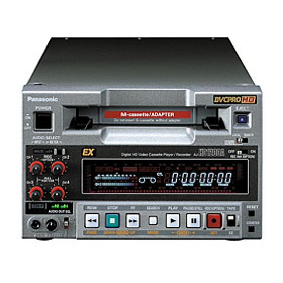
Page 7: Parts And Their Functions
Parts and their functions Front panel REC INH -30 -25 -20 -16 -12 -8 -4 0 CH 1 CH 2 POWER AUDIO SELECT INPUT METER ANALOG PULL FOR VAR 720 P 1·2 3·4 AUDIO OUT SEL AUDIO MON SELECT 1 POWER switch 2 Cassette slot Align the center of the cassette with the center of the slot and push it gently inside. - Page 8 Parts and their functions Front panel 6 REPEAT lamp This lights during repeat playback. <Note> The lamp flashes and repeat playback is not performed if the counter display mode which has been set using menu items No.161 [CTL (TC) BGN] and No.162 [END] is at variance from the counter display mode used for repeat playback.
- Page 9 Parts and their functions Front panel ? ANALOG lamp This lights when ANALOG is selected for the audio input signals as the menu item No.700 [AUDIO IN SEL] setting. When it is off, the HD SDI signal input or INT SG status is established. <Note>...
- Page 10 Parts and their functions Front panel C Analog audio signal recording level controls These are used to adjust the recording levels of the analog audio signals for CH1, CH2, CH3 and CH4 (coupled to CH5, CH6, CH7 and CH8). These are “pull for variable” controls: pull up a control to adjust it.
- Page 11 Parts and their functions Front panel M REC button No optional board installed This unit is a video cassette player so it cannot record by pressing the REC button. When the REC button is pressed, the REC INH lamp on the counter display lights for several seconds.
-
Page 12: Rear Panel
(AJ-A95). The DC power cable is packed together with the AJ-A95. 4 Fuse holder This holds the AC 250 V/2.5 A fuse (time lag type). <Note> Use the fuse specified by Panasonic. Signal Ground ––– ––– +12 V DC OUT... - Page 13 Parts and their functions Rear panel 5 VIDEO OUT (1, 2, Y/G, P /B, P By changing the menu item No.615 [V OUT SEL] setting, either analog composite video signals or HD analog component Y (or G) signals are output from the VIDEO OUT1 connector.
-
Page 14: Tapes
Mini DV, DVCAM cassettes Note that long-playing mini DV cassette tapes (80 minutes in standard mode, 120 minutes in long-playing mode) cannot be used. consumer tapes, recommends the Panasonic brand. M cassettes DVCPRO HD-LP Tapes with recording/playback (AJ-HP33EMG) DVCPRO 25/50/50P HD playback tapes... -
Page 15: Operation
Operation Turning on the unit’s power Before attempting to operate the unit, check whether the equipment has been connected properly. Ensure that the unit is placed on a flat, level surface for operation. Turn on the unit’s power. Insert a cassette tape. Insert the cassette tape at the correct position without forcing it in any way. -
Page 16: Recording
Operation Recording This function can be used only when the AJ-YA120AG (optional accessory) has been installed. Set the cassette tape’s erasure prevention tab to recording enable, and insert the tape. Press the STOP button to set the unit to the STOP mode. -
Page 17: Playback
Operation Playback Insert a cassette tape into the unit. Press the PLAY button. Normal playback now commences. To end playback, press the STOP button. The VTR is set to the stop mode. <Notes> O Check that the SERVO lamp remains lighted during recording. -
Page 18: Linear 0.3K Playback
Operation Linear 0.3k playback The unit is set to the slow still mode when the SEARCH button is pressed during still image playback (PLAY PAUSE). When the FF or REW button is now pressed, the tape is played back at the linear 0.3k speed. Pressing the PAUSE/STILL button during linear 0.3k playback will pause the tape. -
Page 19: Repeat Playback
Operation Repeat playback Setting the BEGIN and END points Set the VTR to the menu mode. (This is done by setting the LOCAL/MENU/ REMOTE switch to the MENU position). Select menu item No.161 [CTL (TC) BGN] or No.162 [END], and press the DATA+ button (PAUSE/STILL button) or DATA- button (PLAY button). -
Page 20: Time Code & User's Bit
Time code & user’s bit Time code The time code signals generated by the time code generator (time code signal generator) are recorded on the tape, and their values are read by the time code reader (time code signal reader) to indicate absolute positions on the tape in increments of hours, minutes, seconds and frames. -
Page 21: Setting The User's Bit
Time code & user’s bit Setting the user’s bit This function can be used only when the AJ-YA120AG (optional accessory) or AJ-YAD120AG (optional accessory) is installed. Set the VTR to the menu mode. (This is done by setting the LOCAL/MENU/ REMOTE switch to the MENU position). -
Page 22: Superimposed Screen Displays
Superimposed screen displays The control signal, time code, etc. are displayed on the TV monitor in the form of abbreviations when the unit’s VIDEO OUT2 connector is connected to a TV monitor. In addition, when the optional AJ-YA120AG is installed, the connector from which the superimposing is output can be changed using the menu item No.005 [SUPER] setting. - Page 23 Superimposed screen displays Operation mode What data is to be displayed can be selected using menu item No.006 [DISPLAY SEL]. TIME: Counter value T&STA: Counter value, VTR operation mode T&S&M: Counter value, VTR operation mode, tape format and error messages T&RT: Counter value, time of recording T&YMD:...
-
Page 24: Setup (Initial Settings)
Setup (initial settings) This unit’s main settings can be performed and checked using the on-screen menus which are displayed on the video monitor connected to the unit. It is also possible to perform and check the settings using the item numbers and setting numbers which are indicated on the front panel display. -
Page 25: Setting The User Defaults
Setup (initial settings) Press the MENU-UP button or MENU-DOWN button to move the cursor to the LOAD position, and press the SET button. The unit is set to the LOAD mode, and the LOAD screen appears on the video monitor. SET–UP MENU <LOAD>... -
Page 26: Loading The User Defaults
Setup (initial settings) Loading the user defaults Set the LOCAL/MENU/REMOTE switch to the MENU position. The unit is set to the menu setting mode, and the menu screen appears on the video monitor. Press the RESET button. The unit is now set to the default setting mode, and the default setting screen now appears on the video monitor. -
Page 27: Releasing The Menu Protection Mode
Setup (initial settings) Set the LOCAL/MENU/REMOTE switch to the LOCAL or REMOTE position. The unit is now set to the menu protection mode. When the LOCAL/MENU/REMOTE switch is set to the MENU position, the unit is not set to the menu setting mode, and “MENU PROTECTED”... -
Page 28: Setup Menus
Setup menus Menus which are displayed The menus displayed differ depending on the setting selected for menu item No.25 [SYSTEM FREQ] and on the optional boards (AJ-YA120AG, AJ-YAD120AG) which have been installed. Superimposed display SYS H (HD) SYS SC (SD) VO SYS H (SD) SD SYS H (SD) SCH COAR (SD) - Page 29 Setup menus Superimposed display TYPE-B NEAR TYPE-B END ID SEL STILL TIMER SRC PROTECT DRUM STDBY STOP PROTECT VITC BLANK VITC POS-1 VITC POS-2 TCG MODE RUN MODE TCG REGEN TC SOURCE BINARY GP PHASE CORR TCG CF FLAG DF MODE TC OUT REF VITC OUT HD EMBD VITC...
- Page 30 Setup menus Superimposed display AUDIO IN SEL CH1 IN LV CH2 IN LV CH3 IN LV CH4 IN LV CH1 OUT LV CH2 OUT LV CH3/L OUT LV CH4/R OUT LV REC CUE PB FADE EMBEDDED AUD DV PB ATT REC PT MUTE AUD RATE CON CUE OUT SEL...
-
Page 31: System
Setup menus SYSTEM Item Setting Superimposed Superimposed display display SYS H (HD) 0000 1100 2200 SYS SC (SD) 0000 0108 0216 VO SYS H (SD) 0000 0858 1716 SD SYS H (SD) 0000 0858 1716 SCH COAR (SD) 0000 0001 0002 0003 SCH FINE (SD) - Page 32 Setup menus SYSTEM Item Setting Superimposed Superimposed display display SYSTEM FREQ 0000 0001 0002 0003 0004 HD SYS H ADV 0000 0001 2 This appears when the AJ-YA120AG (optional accessory) has been installed. “ ” indicates the factory setting. Description of settings For selecting the system frequency 59/60 0: The 59.94 Hz or 60 Hz system frequency is selected.
-
Page 33: Basic
Setup menus BASIC Item Setting Superimposed Superimposed display display LOCAL ENA 0000 0001 0002 TAPE TIMER 0000 0001 REMAIN SEL 0000 0001 0002 0003 SUPER 0000 0001 0002 0003 0004 0005 0006 <Note> Even when OFF is selected as the menu item No.005 [SUPER] setting, the superimposing will be displayed in accordance with what is set using menu item No.006 [DISPLAY SEL] during the menu settings. - Page 34 Setup menus BASIC Item Setting Superimposed Superimposed display display DISPLAY SEL 0000 0001 0002 0003 0004 0005 0006 0007 0008 0009 CHARA H-POS 0000 0006 0037 CHARA V-POS 0000 0023 0032 CHARA TYPE 0000 0001 <Note> If the PAGE button and DATA+ button or DATA– button are pressed when menu items No.007 [CHARA H-POS] and No.008 [CHARA V-POS] are set, the superimposed information is displayed so that its setting can be checked.
- Page 35 Setup menus BASIC Item Setting Superimposed Superimposed display display SYS FORMAT 0000 0001 PB FORMAT 0000 0001 FORMAT SEL 0000 0001 0002 0003 0004 0005 0006 HD FREQUENCY 0000 0001 OUT REF 0000 0001 0002 0003 “ ” indicates the factory setting. Description of settings For setting the format in which to record or play back the signals including the HD REF signals.
- Page 36 Setup menus Formats for playback Depending on how the menu item No.020 [SYS FORMAT], No.022 [PB FORMAT] and No.023 [FORMAL SEL] settings are combined, the formats of the tapes played back by the unit differ as shown in the table below. 022.
-
Page 37: Operation
Setup menus OPERATION Item Setting Superimposed Superimposed display display SHTL MAX 0000 0001 0002 FF.REW MAX 0000 0001 0002 REF ALARM 0000 0001 EJECT EE SEL 0000 0001 0002 EE MODE SEL 0000 0001 PLAY DELAY 0000 0015 CAP LOCK 0000 0001 0002... - Page 38 Setup menus OPERATION Item Setting Superimposed Superimposed display display AUTO REW 0000 0001 FRZ MODE SEL 0000 0001 REC INH LAMP 0000 0001 EJECT SW INH 0000 0001 SP MODE INH 0000 0001 SEARCH SPEED 0000 0001 HUMID OPE 0000 0001 AUTO BACK 0000...
- Page 39 Setup menus OPERATION Item Setting Superimposed Superimposed display display CTL BGN TC BGN REPT MODE 0000 0001 0002 BATTERY SEL 0000 0001 0002 0003 0004 0005 0006 TYPE-A NEAR 0000 0044 TYPE-A END 0000 0034 TYPE-B NEAR 0000 0044 TYPE-B END 0000 0034 “...
-
Page 40: Interface
DVCPRO 1: The DVCPRO ID information is set. ORIG 2: Set this only when the unit is connected to a Panasonic controller (such as the AJ-A900, optional accessory). <Note> Select 1 (DVCPRO) or 2 (ORIG) if “23/24,” “25(HD)” or “25(SD)” is selected as the menu item No.25 [SYSTEM FREQ] setting. -
Page 41: Time Code
Setup menus TIME CODE Item Setting Superimposed Superimposed display display VITC BLANK 0000 0001 VITC POS-1 0000 0006 0010 VITC POS-2 0000 0008 0010 TCG MODE 0000 0001 0002 RUN MODE 0000 0001 TCG REGEN 0000 0001 0002 TC SOURCE 0000 0001 0002... - Page 42 Setup menus TIME CODE Item Setting Superimposed Superimposed display display BINARY GP 0000 0001 0002 0003 0004 0005 0006 0007 PHASE CORR 0000 0001 TCG CF FLAG 0000 0001 DF MODE 0000 0001 TC OUT REF 0000 0001 VITC OUT 0000 0001 HD EMBD VITC...
-
Page 43: Video
Setup menus VIDEO Item Setting Superimposed Superimposed display display VIDEO IN SEL 0000 0001 0002 VIDEO INT SG 0000 0001 0002 0003 0004 0005 SDI IN MODE 0000 0001 V-MUTE SEL 0000 0001 0002 0003 FREEZE SEL 0000 0001 V OUT SEL 0000 0001 OUT MATRIX... - Page 44 Setup menus VIDEO Item Setting Superimposed Superimposed display display U/C ENH H 0000 0001 U/C ENH V 0000 0001 1080i>HD_OUT 0000 0001 720p>HD_OUT 0000 0001 480p>HD_OUT 0000 0001 480i>HD_OUT 0000 0001 BLK CLIP 0000 0001 CC (F1) BLANK 0000 0001 CC (F2) BLANK 0000 0001...
- Page 45 Setup menus VIDEO Item Setting Superimposed Superimposed display display EDH (SD) 0000 0001 ESR MODE (SD) 0000 0001 CCR MODE (SD) 0000 0001 SDI INDEX 0 0000 0001 <Note> With SD output (SD tape playback or down-converted output) 2DW: “ ”...
-
Page 46: Audio
Setup menus AUDIO Item Setting Superimposed Superimposed display display AUDIO IN SEL 0000 0001 0002 CH1 IN LV 0000 0001 0002 0003 CH2 IN LV 0000 0001 0002 0003 CH3 IN LV 0000 0001 0002 0003 CH4 IN LV 0000 0001 0002 0003... - Page 47 Setup menus AUDIO Item Setting Superimposed Superimposed display display REC CUE 0001 0002 0003 0004 0005 0006 0007 0008 0009 0010 0011 0012 0013 PB FADE 0000 0001 0002 EMBEDDED AUD 0000 0001 DV PB ATT 0000 0001 REC PT MUTE 0000 0001 AUD RATE CON...
-
Page 48: Menu
Setup menus AUDIO Item Setting Superimposed Superimposed display display MONITOR MIX 0000 0001 H.PHONE MIX 0000 0001 AUD OUT SEL 0000 0001 0002 IN IMP SEL 0000 0001 MENU Item Setting Superimposed Superimposed display display P.ON LOAD 0000 0001 “ ”... -
Page 49: Dif
Setup menus (This menu appears only when the AJ-YAD120AG board is installed.) Item Setting Superimposed Superimposed display display DIF SPEED 0000 0001 0002 DIF IN CH 0000 0063 0064 DIF OUT CH 0000 0063 0064 DIF CONFIG 0000 0001 0255 DIF AUD OUT 0000 0001... -
Page 50: Error Messages
Error messages When something goes wrong with the unit, one of the following error messages will appear on the front panel’s counter display and on the monitor’s superimposed display. With a superimposed display, the error number will appear in the counter value display area. Error No. - Page 51 Error messages Error No. Error message and description FRONT LOAD ERROR This appears when the take-up reel turns without E – 51 engaging the tape for the prescribed period of time in the start end processing operation while the tape is loading (at the half-loading position).
-
Page 52: Condensation
23: This error message always appears in the E-E mode. In such a case, the time code of the time code generator inside the AJ-HD1200A is recorded as the time code signal. 24: This error message always appears in the E-E mode. -
Page 53: Emergency Eject
This unit comes with an auto head cleaning function which reduces the amount of dirt on the heads automatically. However, in order to improve the unit’s reliability, it is recommended that the video heads be cleaned on a daily basis. Use the cleaning fluid specified by Panasonic. Maintenance Before proceeding with maintenance, set the power switch to OFF, and be absolutely sure to hold the molded part of the power plug to disconnect it from the power outlet. -
Page 54: Specifications
Specifications [GENERAL] Power supply: AC (100-240) V, 50/60 Hz DC 12V, 6.6 A Power consumption: 69 W (main unit only) 97 W (when AJ-YA120AG, AJ-YAD120AG are installed) indicates safety information. Ambient operating temperature: 41°F to 104°F (5°C to 40°C) Ambient operating humidity: 10% to 80% (no condensation) Weight: 17.38 lb (7.9 kg) - Page 55 Specifications $ Video output adjustment ranges HD serial digital output system phase 1080i: ±0.5H (in 13.5ns increments) 59/60 Hz: ±1100 samples 50 Hz: ±1320 samples 23/24 Hz: ±1375 samples 720p: ±0.5H (in 13.5ns increments) 59/60 Hz: ±825 samples SD serial digital/composite video output system phase ±0.5H (in 37ns increments) 59 Hz: ±858 samples...
- Page 56 PANASONIC BROADCAST & TELEVISION SYSTEMS COMPANY UNIT COMPANY OF MATSUSHITA ELECTRIC CORPORATION OF AMERICA Executive Office: One Panasonic Way 4E-7, Secaucus, NJ 07094 (201) 348-7000 EASTERN ZONE: One Panasonic Way 4E-7, Secaucus, NJ 07094 (201) 348-7621 Southeast Region: 1225 Northbrook Parkway, Ste 1-160, Suwanee, GA 30024 (770) 338-6835...