Table of Contents
Advertisement
Quick Links
Advertisement
Table of Contents
Troubleshooting

Related Manuals for Panasonic DP-MB310EU


Summary of Contents for Panasonic DP-MB310EU
- Page 1 ORDER NO.KMF1309430CE Multi-Function printer KX-MB2230EU Model No. KX-MB2270EU KX-MB2515EU KX-MB2545EU KX-MB2575EU DP-MB310EU (for Europe) © Panasonic System Networks Co., Ltd. 2013 Unauthorized copying and distribution is a violation of law.
-
Page 2: Table Of Contents
KX-MB2230EU/ KX-MB2270EU/ KX-MB2515EU/ KX-MB2545EU/ KX-MB2575EU/ DP-MB310EU TABLE OF CONTENTS PAGE PAGE 1 Safety Precautions -----------------------------------------------6 6.8.3. Normal torque 1-2 phase excitation (half 1.1. For Service Technicians ----------------------------------6 step) --------------------------------------------------- 61 1.2. AC Caution---------------------------------------------------6 6.8.4. Flat torque 1-2 phase excitation (half step) 1.3. - Page 3 KX-MB2230EU/ KX-MB2270EU/ KX-MB2515EU/ KX-MB2545EU/ KX-MB2575EU/ DP-MB310EU 6.20.1. Print Process---------------------------------------- 107 12.3.3. Simple Check List --------------------------------- 184 6.20.2. Scanning (ADF) (Only for KX-MB22**)------- 108 12.3.4. Simplified Troubleshooting Guide ------------- 185 6.20.3. Scanning (ADF) (Only for KX-MB25** and 12.3.5. CALL SERVICE Troubleshooting Guide ---- 188 DP-MB***) ------------------------------------------- 109 12.3.6.
- Page 4 KX-MB2230EU/ KX-MB2270EU/ KX-MB2515EU/ KX-MB2545EU/ KX-MB2575EU/ DP-MB310EU 14.3.19. Disassemble the FB Unit (FB-Motor)--------- 298 15.6.1. NG Example----------------------------------------- 334 14.3.20. Disassemble the Operation Panel Assy ----- 299 15.7. Test Chart------------------------------------------------- 335 14.3.21. Remove the Fuser Unit (Fuser Board) ------- 299 15.7.1. ITU-T No.1 Test Chart ---------------------------- 335 14.3.22.
- Page 5 KX-MB2230EU/ KX-MB2270EU/ KX-MB2515EU/ KX-MB2545EU/ KX-MB2575EU/ DP-MB310EU 16.12.1. Operation Board ----------------------------------- 430 18.1.12. Main Chassis Section ---------------------------- 470 16.12.2. Sensor Board --------------------------------------- 431 18.1.13. LSU Section ---------------------------------------- 472 16.13. Sensor Board (DP-MB310) -------------------------- 432 18.1.14. Pick-Up Block Section --------------------------- 474 16.13.1. Operation Board ----------------------------------- 432 18.1.15.
-
Page 6: Safety Precautions
KX-MB2230EU/ KX-MB2270EU/ KX-MB2515EU/ KX-MB2545EU/ KX-MB2575EU/ DP-MB310EU 1 Safety Precautions 1. Before servicing, unplug the AC power cord to prevent an electric shock. 2. When replacing parts, use only the manufacturer's recommended components. 3. Check the condition of the power cord. Replace if wear or damage is evident. -
Page 7: Personal Safety Precautions
KX-MB2230EU/ KX-MB2270EU/ KX-MB2515EU/ KX-MB2545EU/ KX-MB2575EU/ DP-MB310EU 1.3. Personal Safety Precautions 1.3.1. Moving Sections of the Unit Be careful not to let your hair, clothes, fingers, accessories, etc., become caught in any moving sections of the unit. The moving sections of the unit are the rollers and a gear. There is a separation roller and a document feed roller which are rotated by the document feed motor. -
Page 8: Warning
KX-MB2230EU/ KX-MB2270EU/ KX-MB2515EU/ KX-MB2545EU/ KX-MB2575EU/ DP-MB310EU 2 Warning 2.1. About Lead Free Solder (PbF: Pb free) Note: In the information below, Pb, the symbol for lead in the periodic table of elements, will refer to standard solder or solder that con- tains lead. -
Page 9: Discarding Of P. C. Board
KX-MB2230EU/ KX-MB2270EU/ KX-MB2515EU/ KX-MB2545EU/ KX-MB2575EU/ DP-MB310EU 2.2. Discarding of P. C. Board When discarding P. C. Board, delete all personal information such as telephone directory and caller list or scrap P. C. Board. 2.3. Insulation Resistance Test 1. Unplug the power cord and short the two prongs of the plug with a jumper wire. -
Page 10: Note For Repairing
KX-MB2230EU/ KX-MB2270EU/ KX-MB2515EU/ KX-MB2545EU/ KX-MB2575EU/ DP-MB310EU 2.6. Note for Repairing Caution Please inform users of the danger of data being lost at the time of repair. Data will be lost in the following situations. 1. When replacing the ROM ass'y. -
Page 11: Specifications
KX-MB2230EU/ KX-MB2270EU/ KX-MB2515EU/ KX-MB2545EU/ KX-MB2575EU/ DP-MB310EU 3 Specifications Public Switched Telephone Network Applicable Lines Document Size: Scanner glass: Max. 216mm in width, Max. 297mm in length Automatic document feeder: Max. 216mm/Min. 125mm in width, Max. 600mm/Min. 105mm in length Effective Scanning Width:... - Page 12 KX-MB2230EU/ KX-MB2270EU/ KX-MB2515EU/ KX-MB2545EU/ KX-MB2575EU/ DP-MB310EU KX-MB2230/KX-MB2270 Fax Memory Capacity 3.1MB in total Approx. 80 pages of memory reception Approx. 150 pages of memory transmission KX-MB2545/KX-MB2575 7.3MB in total Approx. 350 pages of memory reception Approx. 200 pages of memory transmission DP-MB310 7.9MB in total...
- Page 13 KX-MB2230EU/ KX-MB2270EU/ KX-MB2515EU/ KX-MB2545EU/ KX-MB2575EU/ DP-MB310EU Communications protocol: TCP/IP, SMTP, POP3, SMTP AUTH, POP before SMTP Internet fax Email format: MIME Base 64 Content-type: Image/TIFF Multipart/mixed (text/plain, Image/TIFF) attachment file format Data format: RFC3949 (RFC2301), TIFF-FX minimal set Profile: TIFF-F Encoding scheme: MH/MR/MMR Maximum document size (Width ×...
-
Page 14: General/Introduction
KX-MB2230EU/ KX-MB2270EU/ KX-MB2515EU/ KX-MB2545EU/ KX-MB2575EU/ DP-MB310EU 4 General/Introduction 4.1. Accessory information Replacement accessory To ensure that the unit operates properly, we recommend the use of Panasonic toner and drum cartridges. For KX-MB2230/KX-MB2270 Accessory Model No. (Part No.) Approximate yield (pages) - Page 15 KX-MB2230EU/ KX-MB2270EU/ KX-MB2515EU/ KX-MB2545EU/ KX-MB2575EU/ DP-MB310EU...
- Page 16 KX-MB2230EU/ KX-MB2270EU/ KX-MB2515EU/ KX-MB2545EU/ KX-MB2575EU/ DP-MB310EU...
-
Page 17: General Messages
KX-MB2230EU/ KX-MB2270EU/ KX-MB2515EU/ KX-MB2545EU/ KX-MB2575EU/ DP-MB310EU 4.2.2. General messages... - Page 18 KX-MB2230EU/ KX-MB2270EU/ KX-MB2515EU/ KX-MB2545EU/ KX-MB2575EU/ DP-MB310EU...
- Page 19 KX-MB2230EU/ KX-MB2270EU/ KX-MB2515EU/ KX-MB2545EU/ KX-MB2575EU/ DP-MB310EU...
- Page 20 KX-MB2230EU/ KX-MB2270EU/ KX-MB2515EU/ KX-MB2545EU/ KX-MB2575EU/ DP-MB310EU...
- Page 21 KX-MB2230EU/ KX-MB2270EU/ KX-MB2515EU/ KX-MB2545EU/ KX-MB2575EU/ DP-MB310EU...
- Page 22 KX-MB2230EU/ KX-MB2270EU/ KX-MB2515EU/ KX-MB2545EU/ KX-MB2575EU/ DP-MB310EU...
- Page 23 KX-MB2230EU/ KX-MB2270EU/ KX-MB2515EU/ KX-MB2545EU/ KX-MB2575EU/ DP-MB310EU...
- Page 24 KX-MB2230EU/ KX-MB2270EU/ KX-MB2515EU/ KX-MB2545EU/ KX-MB2575EU/ DP-MB310EU...
- Page 25 KX-MB2230EU/ KX-MB2270EU/ KX-MB2515EU/ KX-MB2545EU/ KX-MB2575EU/ DP-MB310EU...
-
Page 26: Interface Messages
KX-MB2230EU/ KX-MB2270EU/ KX-MB2515EU/ KX-MB2545EU/ KX-MB2575EU/ DP-MB310EU 4.2.3. Interface messages... - Page 27 KX-MB2230EU/ KX-MB2270EU/ KX-MB2515EU/ KX-MB2545EU/ KX-MB2575EU/ DP-MB310EU...
-
Page 28: Features
KX-MB2230EU/ KX-MB2270EU/ KX-MB2515EU/ KX-MB2545EU/ KX-MB2575EU/ DP-MB310EU 5 Features 5.1. General Features General LCD (Liquid Crystal Display) readout Flat-Bed Multifunction Laser Fax Letter/A4/Legal, G3 compatible Automatic document feeder (50 sheets) Resolution: Standard/Fine/Super fine/Photo (64 level). STANDARD: For printed or typewritten originals with normal-sized characters. - Page 29 KX-MB2230EU/ KX-MB2270EU/ KX-MB2515EU/ KX-MB2545EU/ KX-MB2575EU/ DP-MB310EU Windows Internet Explorer 6/7/8/9 Windows Internet Explorer 10 (with compatible mode recommended) Mac OS: Safari 3/4/5/6...
-
Page 30: Technical Descriptions
KX-MB2230EU/ KX-MB2270EU/ KX-MB2515EU/ KX-MB2545EU/ KX-MB2575EU/ DP-MB310EU 6 Technical Descriptions 6.1. Connection Diagram KX -MB25**/DP -MB*** only Docu Sensor RADF KX -MB25**/DP -MB*** only KX -MB22** only Read Position Document RADF JAM SENSOR SENSOR SENSOR with back light PI60 PI59 PI62... -
Page 31: General Block Diagram
KX-MB2230EU/ KX-MB2270EU/ KX-MB2515EU/ KX-MB2545EU/ KX-MB2575EU/ DP-MB310EU 6.2. General Block Diagram MAIN Board SOC (IC300) This custom IC is used for general MFP operations. ARM9 operating at 250MHz. SDRAM Controller Controls SDRAM Memory. USB Controller with PHY ch1:USB device (Apply to USB2.0HS) - Page 32 KX-MB2230EU/ KX-MB2270EU/ KX-MB2515EU/ KX-MB2545EU/ KX-MB2575EU/ DP-MB310EU Low Voltage Power Supply Board (SMPS Board) Supplies +24V and +12V to the Main unit and controls the Heat Lamp. High Voltage Power Supply Board (HVPS Board) Supplies bias need for the printing operation: bias of the DRUM, Developing and Transcription.
- Page 33 KX-MB2230EU/ KX-MB2270EU/ KX-MB2515EU/ KX-MB2545EU/ KX-MB2575EU/ DP-MB310EU...
-
Page 34: Main Board Section
KX-MB2230EU/ KX-MB2270EU/ KX-MB2515EU/ KX-MB2545EU/ KX-MB2575EU/ DP-MB310EU 6.3. Main Board Section 6.3.1. Data Flow [Copy] 1. An analog image data is output from CIS unit to IC503. IC503 decode the analog data to digital data, and output to IC300. Scanner I/F in IC300 process image data and store it in IC400/401 through SDRAM I/F. - Page 35 KX-MB2230EU/ KX-MB2270EU/ KX-MB2515EU/ KX-MB2545EU/ KX-MB2575EU/ DP-MB310EU MB 221x, MB251x is excludes. [FAX Tx] 1. An analog image data is output from CIS unit to IC503. IC503 decode the analog data to digital data, and output to IC300. Scanner I/F in IC300 process image data and store it in IC400/401 through SDRAM I/F.
- Page 36 KX-MB2230EU/ KX-MB2270EU/ KX-MB2515EU/ KX-MB2545EU/ KX-MB2575EU/ DP-MB310EU [PC Scan] 1. An analog image data is output from CIS unit to IC503. IC503 decode the analog data to digital data, and output to IC300. Scanner I/F in IC300 process image data and store it in IC400/401 through SDRAM I/F.
-
Page 37: Scan To Usb Memory
KX-MB2230EU/ KX-MB2270EU/ KX-MB2515EU/ KX-MB2545EU/ KX-MB2575EU/ DP-MB310EU MB 22xx is excludes. [Scan to USB memory] 1. An analog image data is output from CIS unit to IC503. IC503 decode the analog data to digital data, and output to IC300. Scanner I/F in IC300 process image data and store it in IC400/401 through SDRAM I/F. - Page 38 KX-MB2230EU/ KX-MB2270EU/ KX-MB2515EU/ KX-MB2545EU/ KX-MB2575EU/ DP-MB310EU Description of Pin Distribution (IC300) SOC (System On Chip) Pin No. Pin Name Description SDCLK SDRAM Clock SDCKE SDRAM Clock Enable NSDCS SDRAM Chip Select NSDRAS SDRAM Row Address Strobe NSDCAS SDRAM Column Address Strobe...
- Page 39 KX-MB2230EU/ KX-MB2270EU/ KX-MB2515EU/ KX-MB2545EU/ KX-MB2575EU/ DP-MB310EU Pin No. Pin Name Description USBRES2 Pull down USBSEL2 USBDP3 NOT USED (KX-MB22** ONLY) USB(host) Interface (others) USBDM3 NOT USED (KX-MB22** ONLY) USB(host) Interface (others) USBVBUS3 Pull down USBRES3 Pull down USBSEL3 3.3V REF_CLK...
- Page 40 KX-MB2230EU/ KX-MB2270EU/ KX-MB2515EU/ KX-MB2545EU/ KX-MB2575EU/ DP-MB310EU Pin No. Pin Name Description PIO27 SPT Interface PIO28 SPT Interface PIO29 Operation Panel Interface PIO30 Operation Panel Interface PIO31 Operation Panel Interface PIO32 Operation Panel Interface PIO33 NOT USED (KX-MB2*1* ONLY) OUTPUT PORT (CNGMUTE)(Others)
- Page 41 KX-MB2230EU/ KX-MB2270EU/ KX-MB2515EU/ KX-MB2545EU/ KX-MB2575EU/ DP-MB310EU Pin No. Pin Name Description AFESIFCLK Scanner Interface AFESIFEN Scanner Interface AFESIFDIN Scanner Interface AFESIFDOUT Scanner Interface NOT USED NCCDON Scanner Interface LEDONR Scanner Interface LEDONG Scanner Interface LEDONB Scanner Interface AF18 ABITCLK NOT USED (KX-MB2*1* ONLY)
- Page 42 KX-MB2230EU/ KX-MB2270EU/ KX-MB2515EU/ KX-MB2545EU/ KX-MB2575EU/ DP-MB310EU Pin No. Pin Name Description TONE Analog Output (Buzzer) (KX-MB2*1* ONLY) Analog Output (Speaker) (Others) ADVREF DAVREFP DAVREFN NRST Reset NWDTRST Tri-O Watch Dog Timer Reset Signal AD16 TEST NOT USED AC15 TEST_MODE CLKSEL0...
- Page 43 KX-MB2230EU/ KX-MB2270EU/ KX-MB2515EU/ KX-MB2545EU/ KX-MB2575EU/ DP-MB310EU Pin No. Pin Name Description AD12 AD13 AD14 AD22 AD24 AE25...
-
Page 44: Rtc Backup Circuit
KX-MB2230EU/ KX-MB2270EU/ KX-MB2515EU/ KX-MB2545EU/ KX-MB2575EU/ DP-MB310EU 6.3.2. RTC Backup Circuit 1. Function This unit has a lithium battery (BAT300) which works for the Real Time Clock IC (RTC: inside IC300). The RTC continues to work, backed up by a lithium battery even when the power switch is OFF. -
Page 45: Tel Line Section ( Fax Supported Models Only )
KX-MB2230EU/ KX-MB2270EU/ KX-MB2515EU/ KX-MB2545EU/ KX-MB2575EU/ DP-MB310EU 6.3.4. TEL Line Section ( Fax supported models only ) Composed of ITS circuit and NCU circuit. 6.3.4.1. Description of Block Diagram in Analog Section Function The analog section works as an interface between the telephone line. -
Page 46: Block Diagram
KX-MB2230EU/ KX-MB2270EU/ KX-MB2515EU/ KX-MB2545EU/ KX-MB2575EU/ DP-MB310EU 6.3.4.2. Block Diagram... -
Page 47: Ncu Section ( Fax Supported Models Only )
KX-MB2230EU/ KX-MB2270EU/ KX-MB2515EU/ KX-MB2545EU/ KX-MB2575EU/ DP-MB310EU 6.4. NCU Section ( Fax supported models only ) NCU: (Network Control Unit) Requires for connecting computers to public communication networks and send a dial signal to call the other party. 6.4.1. General NCU is the with the telephone line. It is composed of an EXT. TEL. line relay (RLY100), bell detection circuit, TAM interface circuit and line amplifier. -
Page 48: Its
KX-MB2230EU/ KX-MB2270EU/ KX-MB2515EU/ KX-MB2545EU/ KX-MB2575EU/ DP-MB310EU 6.5. ITS (Integrated telephone System) and Monitor Section ( Fax supported models only ) 6.5.1. General The general ITS operation is performed by IC201 which has a handset circuit. The alarm tone, the key tone, and the beep are output from SOC (IC300). -
Page 49: Cis Control Section
KX-MB2230EU/ KX-MB2270EU/ KX-MB2515EU/ KX-MB2545EU/ KX-MB2575EU/ DP-MB310EU 6.6. CIS Control Section The scanning block of this device consists of a control circuit and a CIS (contact image sensor), and AFE (Analog Front End) include A/D Converter. When start the scanning, pin A3 of IC300 will be low level and the transistor Q518 turns on, 3.3V is supplied to the CIS. -
Page 50: Motor Drive Section
KX-MB2230EU/ KX-MB2270EU/ KX-MB2515EU/ KX-MB2545EU/ KX-MB2575EU/ DP-MB310EU 6.7. Motor Drive Section 6.7.1. Main Motor Control Circuit 1. Functions All driving forces of printer engine part are supplied by this main motor. Main motor is controlled so as to rotate at constant speed during printing and copying. - Page 51 KX-MB2230EU/ KX-MB2270EU/ KX-MB2515EU/ KX-MB2545EU/ KX-MB2575EU/ DP-MB310EU <Stop operation> In order to stop the motor rotation, following 2 signals are supplied from IC300. 1. SS signal (Output pin: Pin D24/Output Signal: "L") When this signal is inverted by transistor Q502 and becomes "H", motor recognize this signal as "stop" signal.
-
Page 52: Scanner Motor Drive Circuit
KX-MB2230EU/ KX-MB2270EU/ KX-MB2515EU/ KX-MB2545EU/ KX-MB2575EU/ DP-MB310EU 6.7.2. Scanner motor drive circuit 1. General Scanner motor drive circuit consists of "Motor driver", "Motor current control circuit", and "O.C.P (Over Current Protection) cir- cuit". Scanner motor represents FB (Flatbed) motor and ADF (Auto document Feeder) motor. - Page 53 KX-MB2230EU/ KX-MB2270EU/ KX-MB2515EU/ KX-MB2545EU/ KX-MB2575EU/ DP-MB310EU 6.7.2.1. Motor driver IC502 is the motor driver AN44071A. This motor driver can drive both FB and ADF motors with 1 chip, and can supply up to 1.7A/phase and support up to 2W1-2 phase excitation.
- Page 54 KX-MB2230EU/ KX-MB2270EU/ KX-MB2515EU/ KX-MB2545EU/ KX-MB2575EU/ DP-MB310EU This DC voltage is supplied to VREFAB and VREFCD pins of IC502. When duty of PWM pulse is high, VREFAB and VREFCD voltages are increased and when duty is low, VREFAB and VREFCD voltages are decreased.
-
Page 55: Timing Chart And Wave Form Of Motors
KX-MB2230EU/ KX-MB2270EU/ KX-MB2515EU/ KX-MB2545EU/ KX-MB2575EU/ DP-MB310EU 6.7.3. Timing Chart and Wave Form of Motors 6.7.3.1. Timing Chart of Main and FB Motor 1. 2 Phase excitaton 3. Flat Torque 1-2 Phase excitation 2. Normal Torque 1-2 Phase excitation 4. W1-2 Phase excitation 6.7.3.2. - Page 56 KX-MB2230EU/ KX-MB2270EU/ KX-MB2515EU/ KX-MB2545EU/ KX-MB2575EU/ DP-MB310EU 2. Normal Torque 1-2 Phase excitation CLKAB 5V/Div (Pin39_IC600) AOUT1 (Pin33_IC600) 10V/Div 0.5A/Div FB Motor current* *Motor current is changed according to the motor speed. Fig. 3. Flat Torque 1-2 Phase excitation CLKAB 5V/Div...
- Page 57 KX-MB2230EU/ KX-MB2270EU/ KX-MB2515EU/ KX-MB2545EU/ KX-MB2575EU/ DP-MB310EU 6.7.3.3. Timing Chart of ADF Motor 1. Normal Torque 1-2 Phase excitation 3. W1-2 Phase excitation 2. Flat Torque 1-2 Phase excitation...
- Page 58 KX-MB2230EU/ KX-MB2270EU/ KX-MB2515EU/ KX-MB2545EU/ KX-MB2575EU/ DP-MB310EU 6.7.3.4. Wave Form of ADF Motor 1. Normal Torque 1-2 Phase excitation 2. Flat Torque 1-2 Phase excitation 3. W1-2 Phase excitation...
-
Page 59: Timing Chart And Wave Form Of Scanner Motors
KX-MB2230EU/ KX-MB2270EU/ KX-MB2515EU/ KX-MB2545EU/ KX-MB2575EU/ DP-MB310EU 6.8. Timing chart and wave form of scanner motors 6.8.1. Drive mode of FB and ADF motor Correspondent table of operation... -
Page 60: Phase Excitation
KX-MB2230EU/ KX-MB2270EU/ KX-MB2515EU/ KX-MB2545EU/ KX-MB2575EU/ DP-MB310EU 6.8.2. 2 phase excitation 1. Timing chart 2. Wave form CLKCD 5V/Div (Pin46_IC502) COUT1 (Pin52_IC502) 10V/Div ADF Motor current* 0.5A/Div Fig. 2... -
Page 61: Normal Torque 1-2 Phase Excitation (Half Step)
KX-MB2230EU/ KX-MB2270EU/ KX-MB2515EU/ KX-MB2545EU/ KX-MB2575EU/ DP-MB310EU 6.8.3. Normal torque 1-2 phase excitation (half step) 1. Timing chart 2. Wave form example CLKCD 5V/Div (Pin46_IC502) COUT1 (Pin52_IC502) 10V/Div ADF Motor current* 0.5A/Div Fig. 3 *Motor current is changed according to the scan speed. -
Page 62: Flat Torque 1-2 Phase Excitation (Half Step)
KX-MB2230EU/ KX-MB2270EU/ KX-MB2515EU/ KX-MB2545EU/ KX-MB2575EU/ DP-MB310EU 6.8.4. Flat torque 1-2 phase excitation (half step) 1. Timing chart 2. Wave form example CLKCD 5V/Div (Pin46_IC502) COUT1 (Pin52_IC502) 10V/Div ADF Motor current* 0.5A/Div Fig. 4 *Motor current is changed according to the scan speed. -
Page 63: W 1-2 Phase Excitation (Quarter Step)
KX-MB2230EU/ KX-MB2270EU/ KX-MB2515EU/ KX-MB2545EU/ KX-MB2575EU/ DP-MB310EU 6.8.5. W 1-2 phase excitation (Quarter step) 1. Timing chart 2. Wave form CLKCD 5V/Div (Pin46_IC502) COUT1 (Pin52_IC502) 10V/Div ADF Motor current* 0.5A/Div Fig. 5 *Motor current is changed according to the scan speed. -
Page 64: 2W1-2 Phase Excitation
KX-MB2230EU/ KX-MB2270EU/ KX-MB2515EU/ KX-MB2545EU/ KX-MB2575EU/ DP-MB310EU 6.8.6. 2W1-2 phase excitation 1. Timing chart 2. Wave form CLKCD 5V/Div (Pin46_IC502) COUT1 (Pin52_IC502) 10V/Div ADF Motor current* 0.5A/Div Fig. 6... -
Page 65: Fan Motor Section
KX-MB2230EU/ KX-MB2270EU/ KX-MB2515EU/ KX-MB2545EU/ KX-MB2575EU/ DP-MB310EU 6.9. FAN Motor Section 6.9.1. General This unit is equipped with two FAN motors to prevent the developing devices, Low Voltage Power Supply board (SMPS Board) and other devices from overheating during printing. The FAN rotates at high speed (Approx. 3000rpm) while printing. -
Page 66: Control Table
KX-MB2230EU/ KX-MB2270EU/ KX-MB2515EU/ KX-MB2545EU/ KX-MB2575EU/ DP-MB310EU 6.9.3.2. Full Speed Mode In full speed mode, IC300_pinK25 outputs constant 3.3V. When Q606, Q607 and Q603 are turned on, Vo becomes approx 20V (approx.4V drops between R616, R617). So the voltage between R425 is determined as follows VL=Vo*R624/(R623+R624)=20*22K/(150K+22K)=2.5(V) -
Page 67: Waveform
KX-MB2230EU/ KX-MB2270EU/ KX-MB2515EU/ KX-MB2545EU/ KX-MB2575EU/ DP-MB310EU 6.9.5. Waveform (1)Full speed (H:20usec/Div) Point D(1V/Div) 0.6V Point C(2V/Div) 3.1V 3.3V Point B(2V/Div) Point A(2V/Div) 3.3V Ground level Point F(5V/Div) Point E(10V/Div) 0.6V Point D(1V/Div) Ground level Peak Level (2)Half speed (H:20usec/Div) Point D(1V/Div) 0.6V... - Page 68 KX-MB2230EU/ KX-MB2270EU/ KX-MB2515EU/ KX-MB2545EU/ KX-MB2575EU/ DP-MB310EU 6.9.6.1. FAN motor Lock detect and protection When FAN motor is locked, motor current becomes much more than normal condition. So the voltage between R616 becomes bigger than normal condition, and this causes Q606 turns on.
-
Page 69: Solenoid Driver Section
KX-MB2230EU/ KX-MB2270EU/ KX-MB2515EU/ KX-MB2545EU/ KX-MB2575EU/ DP-MB310EU 6.10. Solenoid Driver Section The solenoid drive circuit controls Registration clutch, Pick up solenoid, ADU solenoid, Switch back solenoid and MPT pick up sole- noid. When duplex scanning, this circuits controls ADF solenoid and ADF switch back solenoid. - Page 70 KX-MB2230EU/ KX-MB2270EU/ KX-MB2515EU/ KX-MB2545EU/ KX-MB2575EU/ DP-MB310EU 2. Active Logic SWITCH BACK MODE IC300_V26 Solenoid ON High level Solenoid OFF Low level MODE IC300_H23 Solenoid ON High level Solenoid OFF Low level RESIST MODE IC300_L26 Clutch ON High level Clutch OFF...
-
Page 71: Optional Lower Input Tray Motor (Opf Motor) Drive And Solenoid Drive Circuit
KX-MB2230EU/ KX-MB2270EU/ KX-MB2515EU/ KX-MB2545EU/ KX-MB2575EU/ DP-MB310EU 6.10.1. Optional Lower input Tray Motor (OPF Motor) Drive and Solenoid Drive circuit 6.10.1.1. General This MFP can add Optional Lower input Tray for improving the performance. OPF motor feed the paper in this tray to the registration roller. - Page 72 KX-MB2230EU/ KX-MB2270EU/ KX-MB2515EU/ KX-MB2545EU/ KX-MB2575EU/ DP-MB310EU After setting the above signals, clock signal is supplied from IC300_pin E26 to IC950_pin14. Whenever clock signal is supplied, current value and direction supplied to Main motor change according to the excitation type which is determined by above signal levels.
- Page 73 KX-MB2230EU/ KX-MB2270EU/ KX-MB2515EU/ KX-MB2545EU/ KX-MB2575EU/ DP-MB310EU (2) Wave form H:2msec/div Point C (5V/Div) Point D (10V/Div) Point E 2. Flat torque 1-2 phase excitation (Half speed) (1) Timing chart...
- Page 74 KX-MB2230EU/ KX-MB2270EU/ KX-MB2515EU/ KX-MB2545EU/ KX-MB2575EU/ DP-MB310EU (2) Wave form H:2msec/div Point C (5V/Div) Point D (10V/Div) Point E...
-
Page 75: Lsu (Laser Scanning Unit) Section
KX-MB2230EU/ KX-MB2270EU/ KX-MB2515EU/ KX-MB2545EU/ KX-MB2575EU/ DP-MB310EU 6.11. LSU (Laser Scanning Unit) Section LSU Layout 216 mm Print Area Laser output OPC DRUM is irradiated with a laser. The sensor outside the effective printing area detects the 1-line operation (scanning). - Page 76 KX-MB2230EU/ KX-MB2270EU/ KX-MB2515EU/ KX-MB2545EU/ KX-MB2575EU/ DP-MB310EU...
-
Page 77: Sensors And Switches Section
KX-MB2230EU/ KX-MB2270EU/ KX-MB2515EU/ KX-MB2545EU/ KX-MB2575EU/ DP-MB310EU 6.12. Sensors and Switches Section All of the sensors and switches are shown below. Sensor Name Sensor Location Reference number Message Error Pick sensor Pick up relay Board PI50 [PAPER JAMMED] Resist sensor Print sensor relay Board... -
Page 78: Pick Up Sensor
KX-MB2230EU/ KX-MB2270EU/ KX-MB2515EU/ KX-MB2545EU/ KX-MB2575EU/ DP-MB310EU 6.12.1. Pick Up Sensor This sensor detects whether a recording paper is picked up or not. When there is a recording paper at the position of the sensor, the input signal of IC300-AD23pin becomes low level. -
Page 79: Ptop Sensor (Print Timing Sensor)
KX-MB2230EU/ KX-MB2270EU/ KX-MB2515EU/ KX-MB2545EU/ KX-MB2575EU/ DP-MB310EU 6.12.3. PTOP Sensor (Print timing Sensor) This sensor detects whether a recording paper is at the printing position. When there is a recording paper at the position of the sensor, the input signal of IC300-AA25pin becomes high level. -
Page 80: Exit Sensor
KX-MB2230EU/ KX-MB2270EU/ KX-MB2515EU/ KX-MB2545EU/ KX-MB2575EU/ DP-MB310EU 6.12.5. Exit Sensor This sensor detects whether a recording paper exits or not. When there is a recording paper at the position of the sensor, the input signal of IC300-AF23pin becomes low level. When there is no recording paper at the position of the sensor, the input signal of IC300-AF23pin becomes high level. -
Page 81: Read Position Sensor
KX-MB2230EU/ KX-MB2270EU/ KX-MB2515EU/ KX-MB2545EU/ KX-MB2575EU/ DP-MB310EU 6.12.7. Read Position Sensor This sensor detects the front edge of the document. When the front edge of the document is detected, the shelter plate closes the sensor light. So the photo-transistor turns off and the input signal of IC300-AB24pin becomes high level. -
Page 82: Radf Jam Sensor (Only For Kx-Mb25** And Dp-Mb***)
KX-MB2230EU/ KX-MB2270EU/ KX-MB2515EU/ KX-MB2545EU/ KX-MB2575EU/ DP-MB310EU 6.12.8. RADF JAM Sensor (Only for KX-MB25** and DP-MB***) This sensor detects the front edge of the document. When the front edge of the document is detected, the shelter plate closes the sensor light. -
Page 83: Paper Sensor
KX-MB2230EU/ KX-MB2270EU/ KX-MB2515EU/ KX-MB2545EU/ KX-MB2575EU/ DP-MB310EU 6.12.10. Paper Sensor This sensor detects whether a recording paper is in casette or not. When there is a recording paper the input signal of IC300-AD26pin becomes high level. When there is no recording paper in casette, the input signal of IC300-AD26pin becomes low level. -
Page 84: Rear Door Sensor
KX-MB2230EU/ KX-MB2270EU/ KX-MB2515EU/ KX-MB2545EU/ KX-MB2575EU/ DP-MB310EU 6.12.12. Rear door Sensor The sensor detects whether the rear cover is open or close. When the rear cover is close, the input signal of IC300-P26pin becomes high level. When the rear cover is open, the input signal of IC300-P26pin becomes low level. -
Page 85: Interlock Switch
KX-MB2230EU/ KX-MB2270EU/ KX-MB2515EU/ KX-MB2545EU/ KX-MB2575EU/ DP-MB310EU 6.12.13. Interlock switch The switches detect whether the front cover is open or close. When the front cover is close, the both switches turn ON, and the input signal of IC300-W25pin becomes Low level. -
Page 86: Toner Sensor
KX-MB2230EU/ KX-MB2270EU/ KX-MB2515EU/ KX-MB2545EU/ KX-MB2575EU/ DP-MB310EU 6.12.14. Toner Sensor This sensor detects whether toner is present. If the time of IC300-AC25pin's Low level is under 0.45s, there is enough toner in Drum cartridge, if not, toner is near empty. Toner Sensor The rest of toner is detected by the move speed of the magnet put on the pendulum of Mixing Paddle. -
Page 87: Opc Life Sensor Circuit
KX-MB2230EU/ KX-MB2270EU/ KX-MB2515EU/ KX-MB2545EU/ KX-MB2575EU/ DP-MB310EU 6.12.15. OPC Life Sensor Circuit 1. General This circuit detects whether the OPC is brand-new or secondhand. And if Drum cartridge is detected as brand-new, after predetermined printing, Fuse, which is installed inside of the OPC is cut. -
Page 88: Toner Life Sensor Circuit
KX-MB2230EU/ KX-MB2270EU/ KX-MB2515EU/ KX-MB2545EU/ KX-MB2575EU/ DP-MB310EU 6.12.16. Toner Life Sensor Circuit 1. General This circuit detects whether the Toner is brand-new or secondhand. And if Toner is detected as brand-new, after predetermined printing, Fuse, which is installed inside of the Toner is cut. -
Page 89: Drum And Toner Detetion
KX-MB2230EU/ KX-MB2270EU/ KX-MB2515EU/ KX-MB2545EU/ KX-MB2575EU/ DP-MB310EU 6.12.17. Drum and Toner Detetion Drum Unit Detection Purpose To describe drum unit detection when the drum unit is inserted. Method By DRUM Life SW (First use sensor) and high pressure abnormal detection signal... - Page 90 KX-MB2230EU/ KX-MB2270EU/ KX-MB2515EU/ KX-MB2545EU/ KX-MB2575EU/ DP-MB310EU...
-
Page 91: Power Switch
KX-MB2230EU/ KX-MB2270EU/ KX-MB2515EU/ KX-MB2545EU/ KX-MB2575EU/ DP-MB310EU 6.12.18. Power Switch 1. Circuit diagram 2. Circuit Explanation 2-1 During the power on 2-1-1 Power switch is pushed → Q814 ON → the logic level of PWRSW port becomes high → If the switch is pushed more than 3seconds, the logic level of SHUTDWN port becomes high →... -
Page 92: Operation Board Section
KX-MB2230EU/ KX-MB2270EU/ KX-MB2515EU/ KX-MB2545EU/ KX-MB2575EU/ DP-MB310EU 6.13. Operation Board Section The unit consists of a LCD (Liquid crystal display), KEYs and LEDs (light-emitting diodes). They are controlled by the Gate Array (IC1) on Operation board and IC300 on Main board. -
Page 93: Lcd Section
KX-MB2230EU/ KX-MB2270EU/ KX-MB2515EU/ KX-MB2545EU/ KX-MB2575EU/ DP-MB310EU 6.14. LCD Section KX-MB22** The Gate Array (IC1) works only for writing the ASCII code from the data bus (D4~D7). V0 is supplied for the LCD drive. R6 and R7 are density control resistors. - Page 94 KX-MB2230EU/ KX-MB2270EU/ KX-MB2515EU/ KX-MB2545EU/ KX-MB2575EU/ DP-MB310EU KX-MB25** The font data is sent from SOC (Main board) throgh the Gate Array(IC1) by serial interface. The contrast is controled by Electronic Volume. LCD reset act at Low level.(RST) Circuit Diagram LCD UNIT...
-
Page 95: Hvps (High Voltage Power Supply) Section
KX-MB2230EU/ KX-MB2270EU/ KX-MB2515EU/ KX-MB2545EU/ KX-MB2575EU/ DP-MB310EU 6.15. HVPS (High Voltage Power Supply) Section 6.15.1. HVPS Specification Charge (CHG) Grid Developing DC Developing AC Transfer (TRA) - Transfer (TRA) + (DEV DC) (DEV AC) Output Characteristics Constant current Constant voltage Constant voltage... -
Page 96: Dev Dc Bias Unit
KX-MB2230EU/ KX-MB2270EU/ KX-MB2515EU/ KX-MB2545EU/ KX-MB2575EU/ DP-MB310EU 6.15.3. DEV DC BIAS UNIT When CHG REM is “L”, 5.425kHz PWM (Pulse Width Modulation) is input from IC300 to DEV CLK through Q504, developing voltage corresponding to the DUTY of PWM signal is output from DEV OUTPUT. Also DUTY is adjusted by the utilization of the developing unit and environmental temperature. -
Page 97: Heat Lamp Control Circuit
KX-MB2230EU/ KX-MB2270EU/ KX-MB2515EU/ KX-MB2545EU/ KX-MB2575EU/ DP-MB310EU 6.16. Heat Lamp Control Circuit The temperature of the fixing part of the Fuser Unit is converted to a Voltage by THERMISTOR and input to IC300_pinC21. The heat lamp is turned on/off by the HTRCTL signal (IC300_pinAE22) through the photo triac (PC2) and the triac (SCR21). - Page 98 KX-MB2230EU/ KX-MB2270EU/ KX-MB2515EU/ KX-MB2545EU/ KX-MB2575EU/ DP-MB310EU...
- Page 99 KX-MB2230EU/ KX-MB2270EU/ KX-MB2515EU/ KX-MB2545EU/ KX-MB2575EU/ DP-MB310EU 2. Safety Protection a. 2 thermostats are provided with the unit, and the heater circuit is shut down when their surface temperatures became over 170 °C. b. The heater control circuit of IC300 has the built-in function that the hardware turns off the heater control automatically if the software does not keep turning ON the heater every a fixed time.
- Page 100 KX-MB2230EU/ KX-MB2270EU/ KX-MB2515EU/ KX-MB2545EU/ KX-MB2575EU/ DP-MB310EU Temperature AD value HEX reading Temperature AD value HEX reading Temperature AD value HEX reading [C°] [C°] [C°] Note: The value is displayed on LCD at Test Functions (P.136) [#815].
- Page 101 KX-MB2230EU/ KX-MB2270EU/ KX-MB2515EU/ KX-MB2545EU/ KX-MB2575EU/ DP-MB310EU 4. The correspondence readings between room temperature measured bye thermistor and HEX readings You can read the AD value of room temperature in service mode. Push the keys [MENU]-[#]-[9][0][0][0]-[ ]-[8][1][5]. LCD indicates as below.
-
Page 102: Power Saving (Sleep) Function
KX-MB2230EU/ KX-MB2270EU/ KX-MB2515EU/ KX-MB2545EU/ KX-MB2575EU/ DP-MB310EU 6.17. Power Saving (Sleep) Function The system circuit and the power supply circuit have a function which reduces power consumption. It is performed at the time of not operating condition (Sleep). The content is as follows. -
Page 103: Main Board Power Supply Section
KX-MB2230EU/ KX-MB2270EU/ KX-MB2515EU/ KX-MB2545EU/ KX-MB2575EU/ DP-MB310EU 6.18. Main Board Power Supply Section 6.18.1. 3.3V and 1.2V Power Supply Descriptions 1. IC800, IC801 is Synchronous Step-Down DC/DC Converter with Auto-Skip Eco-mode to increase light load efficiency. 2. Oscillation frequency is set at approximately 700kHz (Frequency is changed at Light Load.). -
Page 104: Power Supply Descriptions
KX-MB2230EU/ KX-MB2270EU/ KX-MB2515EU/ KX-MB2545EU/ KX-MB2575EU/ DP-MB310EU 6.18.3. 24V Power Supply Descriptions 1. The switch circuit which turns off a +24V power supply at the time of Sleep mode. +24V P24VA +24VA P24VB +24VB Q807 Q813 S3.3V S3.3V Q806 Q812 6.18.4. 2.5V Power Supply Descriptions 1. -
Page 105: Main Unit Power Supply Sequence
KX-MB2230EU/ KX-MB2270EU/ KX-MB2515EU/ KX-MB2545EU/ KX-MB2575EU/ DP-MB310EU 6.18.6. Main Unit Power Supply Sequence 6.18.7. Wave Form [3.3V DCDC] Ready Mode Sleep Mode 7.5V [1.2V DCDC] Ready Mode Sleep Mode 7.5V [5V DCDC] Ready Mode Sleep Mode 7.5V... -
Page 106: Power Supply Board Section
KX-MB2230EU/ KX-MB2270EU/ KX-MB2515EU/ KX-MB2545EU/ KX-MB2575EU/ DP-MB310EU 6.19. Power Supply Board Section The power supply board circuit generates 24Vdc and 12Vdc at normal mode. It also supplies AC voltage to the halogen heat lamp in the fuser unit. The power supply board uses the switching regulator method, and it has a power save function. -
Page 107: Mechanical Operation
KX-MB2230EU/ KX-MB2270EU/ KX-MB2515EU/ KX-MB2545EU/ KX-MB2575EU/ DP-MB310EU 6.20. Mechanical Operation 6.20.1. Print Process Exit Roller Registration Roller Fuser Roller Feed Roller Transfer Roller Separation Roller Pick Up Roller ADU feed Roller This Laser Printer creates an image on paper using a technique called laser electrophotography. The printer uses the electro- graphic process known as Discharged Area Development, or “write black”. -
Page 108: Scanning (Adf) (Only For Kx-Mb22**)
KX-MB2230EU/ KX-MB2270EU/ KX-MB2515EU/ KX-MB2545EU/ KX-MB2575EU/ DP-MB310EU 6.20.2. Scanning (ADF) (Only for KX-MB22**) SEPARATION ROLLER (DOC.) PICK UP ROLLER (DOC.) SEPARATION RUBBER ROLLER DOC EJECT FEED ROLLER (DOC.) • DOCUMENT TRANSMISSION (ADF) The frictional force between SEPARATION ROLLER (DOC.)and SEPARATION RUBBER makes PICK UP ROLLER (DOC.) move downward from standby position to pick up paper. -
Page 109: Scanning (Adf) (Only For Kx-Mb25** And Dp-Mb***)
KX-MB2230EU/ KX-MB2270EU/ KX-MB2515EU/ KX-MB2545EU/ KX-MB2575EU/ DP-MB310EU 6.20.3. Scanning (ADF) (Only for KX-MB25** and DP-MB***) 6.20.3.1. General This Auto Document Feeder (ADF) can read double side documents as well as single side documents. ADF motor supplies all power to rotate the rollers. -
Page 110: Double Side Scanning
KX-MB2230EU/ KX-MB2270EU/ KX-MB2515EU/ KX-MB2545EU/ KX-MB2575EU/ DP-MB310EU 6.20.4. Double side Scanning 1. When the paper arrive at TOP sensor, ADF motor reverse to up the pick up roller. TOP SENSOR 2. When the top of documents pass the CIS, paperpass change solenoid become "ON". - Page 111 KX-MB2230EU/ KX-MB2270EU/ KX-MB2515EU/ KX-MB2545EU/ KX-MB2575EU/ DP-MB310EU 6. When the top of documents pass the CIS, paperpass change solenoid become "ON". Then document is fed to the upper paper pass. 7. When the end of document pass the switchback roller, switchback solenoid "OFF" for changing the direction of rotation.
-
Page 112: Wirelesslan Section
KX-MB2230EU/ KX-MB2270EU/ KX-MB2515EU/ KX-MB2545EU/ KX-MB2575EU/ DP-MB310EU 6.21. WirelessLAN Section ( WirelessLAN supported models only ) WirelessLAN block consists of WirelessLAN module IC (IC850) and antenna switch IC (IC851). IC300 and IC850 communicate by USB2.0. IC850 transmits and receives the signal of a 2.4GHz with an antenna 1 or antenna 2. -
Page 113: Location Of Controls And Components
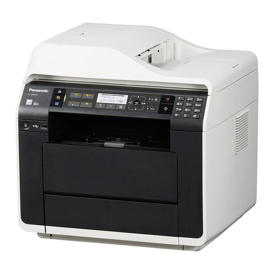
KX-MB2230EU/ KX-MB2270EU/ KX-MB2515EU/ KX-MB2545EU/ KX-MB2575EU/ DP-MB310EU 7 Location of Controls and Components 7.1. Overview 7.1.1. Front View (1) Power switch (2) USB port (KX-MB2515/KX-MB2545/KX-MB2575/DP- MB310 ONLY) (3) ADF (Automatic Document Feeder) cover (4) Output tray (5) Document entrance (6) Document guides... -
Page 114: Rear View
KX-MB2230EU/ KX-MB2270EU/ KX-MB2515EU/ KX-MB2545EU/ KX-MB2575EU/ DP-MB310EU 7.1.2. Rear View (1) LED (2) LAN interface connector •10Base-T/100Base-TX (3) Rear cover (4) Power inlet (5) Telephone line socket (KX-MB2230/KX-MB2270/KX- MB2545/KX-MB2575/DP-MB310 ONLY) (6) External telephone line socket (KX-MB2230/KX- MB2270/KX-MB2545/KX-MB2575/DP-MB310 ONLY) (7) USB interface connector... -
Page 115: Control Panel
KX-MB2230EU/ KX-MB2270EU/ KX-MB2515EU/ KX-MB2545EU/ KX-MB2575EU/ DP-MB310EU 7.2. Control Panel (1) [ (Broadcast) (14) [ ] (Copy Size) ] (Redial) (2) [ ] (Scan) ] (Pause) (3) [ ] (Quality) (15) [ ] (Zoom) ] (Quality) [R] (Recall) (4) [ ] (Page Layout) -
Page 116: Installation Instructions
KX-MB2230EU/ KX-MB2270EU/ KX-MB2515EU/ KX-MB2545EU/ KX-MB2575EU/ DP-MB310EU 8 Installation Instructions 8.1. Installation 8.1.1. Installation Space The space required to install the unit is shown below. The dimensions given are necessary for the unit to operate efficiently. Note: • Avoid excessive heat or humidity. -
Page 117: Recording Paper
KX-MB2230EU/ KX-MB2270EU/ KX-MB2515EU/ KX-MB2545EU/ KX-MB2575EU/ DP-MB310EU 8.1.2. Recording Paper Note for recording paper: • We recommend that you test paper (especially special sizes and types of paper) on the unit before purchasing large quantities. • Do not use the following types of paper:... - Page 118 KX-MB2230EU/ KX-MB2270EU/ KX-MB2515EU/ KX-MB2545EU/ KX-MB2575EU/ DP-MB310EU Adjust the back side of the recording paper guide. For A4, letter, legal, 16K, 216 × 330 mm, 216 × 340 mm size paper: Pinch the knob (1), and slide the input tray extender (2) to the appropriate position.
- Page 119 KX-MB2230EU/ KX-MB2270EU/ KX-MB2515EU/ KX-MB2545EU/ KX-MB2575EU/ DP-MB310EU • If necessary, slide the recording paper guides to adjust the width to the size of the recording paper. • Make sure that the recording paper is under the paper limit mark (1), and the paper should not be loaded over the snubbers (2).
- Page 120 KX-MB2230EU/ KX-MB2270EU/ KX-MB2515EU/ KX-MB2545EU/ KX-MB2575EU/ DP-MB310EU Caution for the Standard input tray • Do not drop the Standard input tray. • Hold the Standard input tray with both hands when removing or installing. The Standard input tray weighs approximately 3.6 kg...
- Page 121 KX-MB2230EU/ KX-MB2270EU/ KX-MB2515EU/ KX-MB2545EU/ KX-MB2575EU/ DP-MB310EU 8.1.2.2. Manual tray/Multi-purpose tray • When printing from a computer, custom size recording paper can also be used. • The unit is set for printing A4-size plain paper by default. - To use other paper sizes, change the recording paper size setting (feature #381).
- Page 122 KX-MB2230EU/ KX-MB2270EU/ KX-MB2515EU/ KX-MB2545EU/ KX-MB2575EU/ DP-MB310EU Multi-purpose tray It can hold 50 sheets at a time. Expand the multi-purpose tray. Adjust the width of the guides (1) to the size of the recording paper. Then, load the paper, print-side up (up to 50 sheets).
-
Page 123: Documents The Unit Can Send
KX-MB2230EU/ KX-MB2270EU/ KX-MB2515EU/ KX-MB2545EU/ KX-MB2575EU/ DP-MB310EU 8.1.3. Documents the Unit Can Send Note: • Confirm that there are no documents in the automatic document feeder. • Place the original onto the scanner glass gently. To avoid malfunction, do not press down too firmly. - Page 124 KX-MB2230EU/ KX-MB2270EU/ KX-MB2515EU/ KX-MB2545EU/ KX-MB2575EU/ DP-MB310EU • For A6 size documents, always insert the document in portrait direction (insert long edge into the feeder). • Adjust the width of the document guides (1) to fit the actual size of the document.
-
Page 125: Toner Cartridge And Drum Cartridge
• Do not leave the toner cartridge out of the protective bag for a long time. It will affect the printing quality. • Do not add toner to the toner cartridge. We cannot be responsible for any damage to the unit or degradation of print quality which may occur from the use of a non-Panasonic toner cartridge and drum cartridge. Note: •... - Page 126 KX-MB2230EU/ KX-MB2270EU/ KX-MB2515EU/ KX-MB2545EU/ KX-MB2575EU/ DP-MB310EU Remove the drum cartridge (1), which is pre-installed in the unit. Remove the protective sheet (1) from the drum cartridge. • Do not touch or scratch the drum surface. • “PAPER JAMMED” is displayed before the protective sheet is removed.
- Page 127 Detach the orange protective cover (1) from the toner cartridge. • Do not touch the roller. Hold the toner cartridge (1) by the centre handle, then insert firmly to lock into place. Close the front cover.
-
Page 128: Required Computer Environment
• To maintain print quality and machine life, we recommend that you clean slots and openings and the inside of the unit when replacing the toner cartridge and/or drum cartridge. Note: • To ensure that the unit operates properly, we recommend the use of Panasonic toner cartridge and drum cartridge. (Refer to Accessory information (P.14).) Waste disposal method Waste material should be disposed of under conditions which meet all national and local environmental regulations. -
Page 129: Installing Software
8.1.7. Installing software (including printer, scanner and other drivers) Panasonic Multi-Function Station software enables the unit to carry out the following functions: - Printing on plain paper, thin and thick paper, labels, envelope and Japan postcard - Displaying the preview of the print image, changing the page order, deleting pages, and changing the print layout etc. before... - Page 130 KX-MB2230EU/ KX-MB2270EU/ KX-MB2515EU/ KX-MB2545EU/ KX-MB2575EU/ DP-MB310EU Important notice When installing using a USB cable connection, a message may appear during the software installation. This is normal and the software will not cause any difficulties with your operating system. You can continue the installation with no problem. This kind of message is displayed: •...
-
Page 131: Connections
KX-MB2230EU/ KX-MB2270EU/ KX-MB2515EU/ KX-MB2545EU/ KX-MB2575EU/ DP-MB310EU 8.2. Connections Caution: • When you operate this product, the power outlet should be near the product and easily accessible. • Be sure to use the telephone line cord supplied with this unit (fax supported models only). - Page 132 KX-MB2230EU/ KX-MB2270EU/ KX-MB2515EU/ KX-MB2545EU/ KX-MB2575EU/ DP-MB310EU Note: • An earthed contact socket should be used when connecting the unit to the power outlet (for Poland only). • Do not place any objects within the following distance: - Right and left side: 10 cm - Back side: 20 cm •...
-
Page 133: Operating Instructions
KX-MB2230EU/ KX-MB2270EU/ KX-MB2515EU/ KX-MB2545EU/ KX-MB2575EU/ DP-MB310EU 9 Operating Instructions 9.1. Your Logo (Fax supported models only) You can program your logo (name, company name, etc.) so that it appears on the top of each page sent. -
Page 134: Character Entry (Fax Or Lan Supported Models Only)
KX-MB2230EU/ KX-MB2270EU/ KX-MB2515EU/ KX-MB2545EU/ KX-MB2575EU/ DP-MB310EU 9.2. Character Entry (Fax or LAN supported models only) The dial keypad is used to enter characters and numbers. - Press [ ] or [ ] to move the cursor. - Press the dial keys to enter characters and numbers. -
Page 135: To Select Characters Using [] Or []
KX-MB2230EU/ KX-MB2270EU/ KX-MB2515EU/ KX-MB2545EU/ KX-MB2575EU/ DP-MB310EU 9.2.1. To Select Characters Using [ ] or [ ]... -
Page 136: Test Mode
KX-MB2230EU/ KX-MB2270EU/ KX-MB2515EU/ KX-MB2545EU/ KX-MB2575EU/ DP-MB310EU 10 Test Mode 10.1. Test Functions The codes listed below can be used to perform simple checks of some of the unit’s functions. When complaints are received from customers, they provide an effective tool for identifying the locations and causes of malfunctions. -
Page 137: Dtmf Single Tone Transmit Selection
KX-MB2230EU/ KX-MB2270EU/ KX-MB2515EU/ KX-MB2545EU/ KX-MB2575EU/ DP-MB310EU Test Mode Type of Mode Code Function Operation after code input SENSOR CHECK Service Mode “8” “1” “5” First of all, press the copy button, and confirm the action of ON/OFF. For each sensor’s operation, refer to Sensors and Switches Section (P.77). -
Page 138: Button Code Table
KX-MB2230EU/ KX-MB2270EU/ KX-MB2515EU/ KX-MB2545EU/ KX-MB2575EU/ DP-MB310EU 10.1.2. Button Code Table (KX-MB2230/KX-MB2545 ONLY) 10.1.3. Button Code Table (KX-MB2270/KX-MB2575 ONLY) -
Page 139: Button Code Table (Kx-Mb2515 Only)
KX-MB2230EU/ KX-MB2270EU/ KX-MB2515EU/ KX-MB2545EU/ KX-MB2575EU/ DP-MB310EU 10.1.4. Button Code Table (KX-MB2515 ONLY) 10.1.5. Button Code Table (DP-MB310 ONLY) -
Page 140: Print Test Pattern
KX-MB2230EU/ KX-MB2270EU/ KX-MB2515EU/ KX-MB2545EU/ KX-MB2575EU/ DP-MB310EU 10.1.6. Print Test Pattern 1. NO.01 3. NO.03 2. NO.06 • These print test patterns are just image printing, and differ- ent from actual ones. • When it is required to judge the print quality, compare with... -
Page 141: Service Mode
KX-MB2230EU/ KX-MB2270EU/ KX-MB2515EU/ KX-MB2545EU/ KX-MB2575EU/ DP-MB310EU 11 Service Mode The programming functions are used to program the various features and functions of the machine, and to test the machine. This facilitates communication between the user and the service man while programming the unit. -
Page 142: Service Function Table
KX-MB2230EU/ KX-MB2270EU/ KX-MB2515EU/ KX-MB2545EU/ KX-MB2575EU/ DP-MB310EU 11.1.3. Service Function Table Code Function Set Value Effective Default Remarks Range Call Service Clear Memory clear Refer to Memory Clear Specification (P.145). ROM check See Test Functions (P.136). Scanner test See Test Functions (P.136). -
Page 143: Service Function Table ( Fax Supported Models Only )
KX-MB2230EU/ KX-MB2270EU/ KX-MB2515EU/ KX-MB2545EU/ KX-MB2575EU/ DP-MB310EU 11.1.4. Service Function Table ( Fax supported models only ) Code Function Set Value Effective Default Remarks Range Pause time set X 100msec 001~600 ---------- Dial speed select 1: 10pps 1, 2 ---------- 2: 20pps... - Page 144 KX-MB2230EU/ KX-MB2270EU/ KX-MB2515EU/ KX-MB2545EU/ KX-MB2575EU/ DP-MB310EU Code Function Set Value Effective Default Remarks Range Time between CED and 300bps 1: 75msec See How To Output The Journal Report (P.224) 2: 500msec and Receive Problem (P.218). 3: 1sec Overseas DIS detection select...
-
Page 145: Memory Clear Specification
KX-MB2230EU/ KX-MB2270EU/ KX-MB2515EU/ KX-MB2545EU/ KX-MB2575EU/ DP-MB310EU Code Function Set Value Effective Default Remarks Range Left margin (DUPLEX) X 0.5mm 01~11 ---------- History list See History (Example of a printed out list) (P.164). Journal 2 list See Journal 2 (P.221). Journal 3 list See Journal 3 (P.222). -
Page 146: User Mode (The List Below Is An Example Of The System Setup List The Unit Prints Out.)
KX-MB2230EU/ KX-MB2270EU/ KX-MB2515EU/ KX-MB2545EU/ KX-MB2575EU/ DP-MB310EU 11.2. User Mode (The list below is an example of the SYSTEM SETUP LIST the unit prints out.) (KX-MB2230) - Page 147 KX-MB2230EU/ KX-MB2270EU/ KX-MB2515EU/ KX-MB2545EU/ KX-MB2575EU/ DP-MB310EU...
- Page 148 KX-MB2230EU/ KX-MB2270EU/ KX-MB2515EU/ KX-MB2545EU/ KX-MB2575EU/ DP-MB310EU (KX-MB2270)
- Page 149 KX-MB2230EU/ KX-MB2270EU/ KX-MB2515EU/ KX-MB2545EU/ KX-MB2575EU/ DP-MB310EU...
- Page 150 KX-MB2230EU/ KX-MB2270EU/ KX-MB2515EU/ KX-MB2545EU/ KX-MB2575EU/ DP-MB310EU (KX-MB2515)
- Page 151 KX-MB2230EU/ KX-MB2270EU/ KX-MB2515EU/ KX-MB2545EU/ KX-MB2575EU/ DP-MB310EU...
- Page 152 KX-MB2230EU/ KX-MB2270EU/ KX-MB2515EU/ KX-MB2545EU/ KX-MB2575EU/ DP-MB310EU (KX-MB2545)
- Page 153 KX-MB2230EU/ KX-MB2270EU/ KX-MB2515EU/ KX-MB2545EU/ KX-MB2575EU/ DP-MB310EU...
- Page 154 KX-MB2230EU/ KX-MB2270EU/ KX-MB2515EU/ KX-MB2545EU/ KX-MB2575EU/ DP-MB310EU...
- Page 155 KX-MB2230EU/ KX-MB2270EU/ KX-MB2515EU/ KX-MB2545EU/ KX-MB2575EU/ DP-MB310EU (KX-MB2575)
- Page 156 KX-MB2230EU/ KX-MB2270EU/ KX-MB2515EU/ KX-MB2545EU/ KX-MB2575EU/ DP-MB310EU...
- Page 157 KX-MB2230EU/ KX-MB2270EU/ KX-MB2515EU/ KX-MB2545EU/ KX-MB2575EU/ DP-MB310EU...
- Page 158 KX-MB2230EU/ KX-MB2270EU/ KX-MB2515EU/ KX-MB2545EU/ KX-MB2575EU/ DP-MB310EU (DP-MB310EU)
- Page 159 KX-MB2230EU/ KX-MB2270EU/ KX-MB2515EU/ KX-MB2545EU/ KX-MB2575EU/ DP-MB310EU...
- Page 160 KX-MB2230EU/ KX-MB2270EU/ KX-MB2515EU/ KX-MB2545EU/ KX-MB2575EU/ DP-MB310EU Note: The above values are the default values.
-
Page 161: Service Mode Settings (Example Of A Printed Out List)
KX-MB2230EU/ KX-MB2270EU/ KX-MB2515EU/ KX-MB2545EU/ KX-MB2575EU/ DP-MB310EU 11.3. Service Mode Settings (Example of a printed out list) (KX-MB2230) (KX-MB2270) - Page 162 KX-MB2230EU/ KX-MB2270EU/ KX-MB2515EU/ KX-MB2545EU/ KX-MB2575EU/ DP-MB310EU (KX-MB2545) (KX-MB2575)
- Page 163 KX-MB2230EU/ KX-MB2270EU/ KX-MB2515EU/ KX-MB2545EU/ KX-MB2575EU/ DP-MB310EU (DP-MB310EU) Note: The above values are the default values.
-
Page 164: History (Example Of A Printed Out List)
KX-MB2230EU/ KX-MB2270EU/ KX-MB2515EU/ KX-MB2545EU/ KX-MB2575EU/ DP-MB310EU 11.4. History (Example of a printed out list) (KX-MB2230) - Page 165 KX-MB2230EU/ KX-MB2270EU/ KX-MB2515EU/ KX-MB2545EU/ KX-MB2575EU/ DP-MB310EU (KX-MB2270)
- Page 166 KX-MB2230EU/ KX-MB2270EU/ KX-MB2515EU/ KX-MB2545EU/ KX-MB2575EU/ DP-MB310EU (KX-MB2515)
- Page 167 KX-MB2230EU/ KX-MB2270EU/ KX-MB2515EU/ KX-MB2545EU/ KX-MB2575EU/ DP-MB310EU (KX-MB2545)
- Page 168 KX-MB2230EU/ KX-MB2270EU/ KX-MB2515EU/ KX-MB2545EU/ KX-MB2575EU/ DP-MB310EU (KX-MB2575)
- Page 169 KX-MB2230EU/ KX-MB2270EU/ KX-MB2515EU/ KX-MB2545EU/ KX-MB2575EU/ DP-MB310EU (DP-MB310EU) Note: *1) Factory to Now(Day) shows the actual number of days from the production to print History. This is nothing to do with how many times or how long the power is on *See the following descriptions of this report.
-
Page 170: Descriptions Of The History Report
KX-MB2230EU/ KX-MB2270EU/ KX-MB2515EU/ KX-MB2545EU/ KX-MB2575EU/ DP-MB310EU 11.4.1. Descriptions of the History Report (1) Not used (KX-MB2515 Only) Usage Time of Receive Mode (Tel Mode) (2) Not used (KX-MB2515 Only) Usage Time of Receive Mode (Fax Mode) (3) Not used (KX-MB2515 Only) -
Page 171: Troubleshooting Guide
KX-MB2230EU/ KX-MB2270EU/ KX-MB2515EU/ KX-MB2545EU/ KX-MB2575EU/ DP-MB310EU 12 Troubleshooting Guide 12.1. User Recoverable Errors If the unit detects a problem, one or more of the following messages will appear on the display. The explanations given in the [ ] are for servicemen only. - Page 172 KX-MB2230EU/ KX-MB2270EU/ KX-MB2515EU/ KX-MB2545EU/ KX-MB2575EU/ DP-MB310EU DISPLAY MESSAGE CAUSE AND REMEDY • The unit is cooling down the fuser unit. Wait for a while. • The drum cartridge is reaching the end of its life. If you don’t have a new cartridge handy you should buy one as soon as possible as your current cartridge is near the end of its useful life.
- Page 173 KX-MB2230EU/ KX-MB2270EU/ KX-MB2515EU/ KX-MB2545EU/ KX-MB2575EU/ DP-MB310EU DISPLAY MESSAGE CAUSE AND REMEDY • The other party’s fax machine is busy or has run out of recording paper. Try again. • The document is jammed. Remove the jammed document. • Attempted to send or copy a document longer than 600 mm using the automatic document feeder.
- Page 174 KX-MB2230EU/ KX-MB2270EU/ KX-MB2515EU/ KX-MB2545EU/ KX-MB2575EU/ DP-MB310EU Interface messages DISPLAY MESSAGE CAUSE AND REMEDY • IP address of the server or network configuration is incorrect. Consult your network administrator. • The server is down. Consult your network administrator. • The cable between the unit and the computer is not connected correctly.Check the connections.
-
Page 175: Remote Programming
KX-MB2230EU/ KX-MB2270EU/ KX-MB2515EU/ KX-MB2545EU/ KX-MB2575EU/ DP-MB310EU 12.2. Remote Programming If, after the call is connected, the customer describes the situation and it is determined that the problem can be corrected by making parameter changes, this function makes it possible to change parameters such as the user code and service code from another fax (using DTMF tones). -
Page 176: Entering The Remote Programming Mode And Changing Service Codes
KX-MB2230EU/ KX-MB2270EU/ KX-MB2515EU/ KX-MB2545EU/ KX-MB2575EU/ DP-MB310EU 12.2.1. Entering the Remote Programming Mode and Changing Service Codes CROSS REFERENCE: Program Mode Table (P.177) -
Page 177: Program Mode Table
KX-MB2230EU/ KX-MB2270EU/ KX-MB2515EU/ KX-MB2545EU/ KX-MB2575EU/ DP-MB310EU 12.2.2. Program Mode Table 12.2.2.1. User Function Basic features Code Function Set Value Default Remote Setting SET DATE & TIME*1 dd/mm/yy hh:mm 01/01/13 00:00 YOUR LOGO*2 --------- None YOUR FAX NUMBER*2 --------- None LANGUAGE... - Page 178 KX-MB2230EU/ KX-MB2270EU/ KX-MB2515EU/ KX-MB2545EU/ KX-MB2575EU/ DP-MB310EU Fax features (KX-MB2230/KX-MB2545/KX-MB2575/DP-MB310 ONLY) Code Function Set Value Default Remote Setting TEL/FAX DELAYED RING REMOTE TURN ON 0:OFF / 1:ON PRINT SENDING REPORT 0:OFF / 1:ON / 2:ERROR ERROR JOURNAL AUTO PRINT 0:OFF / 1:ON...
- Page 179 KX-MB2230EU/ KX-MB2270EU/ KX-MB2515EU/ KX-MB2545EU/ KX-MB2575EU/ DP-MB310EU Code Function Set Value Default Remote Setting PRINT FORMAT 1:LETTER 2:A4 3:LEGAL 4:B5(ISO) 5:B5(JIS) 6:16K 7:216x330 / 8:216x340 / 9:A6 / 10:A5 / 11:B6(ISO) / 12:B6(JIS) Note*1 IMAGE REDUCTION 0:OFF / 1:ON PCL ORIENTATION...
- Page 180 KX-MB2230EU/ KX-MB2270EU/ KX-MB2515EU/ KX-MB2545EU/ KX-MB2575EU/ DP-MB310EU Code Function Set Value Default Remote Setting WINS SERVER #1 --------- --------- WINS SERVER #2 --------- --------- ADDRESS ON WEB 0:DISABLED / 1:ENABLED ENABLED JOURNAL ON WEB 0:DISABLED / 1:ENABLED ENABLED ERASE ADDRESS YES / NO...
- Page 181 KX-MB2230EU/ KX-MB2270EU/ KX-MB2515EU/ KX-MB2545EU/ KX-MB2575EU/ DP-MB310EU 12.2.2.2. Service Function Code Function Set Value Default Remote Setting Pause time set 001~600 x 100msec Dial speed 1:10pps / 2:20pps 10pps V34 transmission start speed 0:Disable / 1:33.6 / 2:31.2 / 3:28.8 / 33,600bps 4:26.4 / 5:24.0 / 6:21.6 / 7:19.2 / 8:16.8...
- Page 182 KX-MB2230EU/ KX-MB2270EU/ KX-MB2515EU/ KX-MB2545EU/ KX-MB2575EU/ DP-MB310EU Code Function Set Value Default Remote Setting History list --------- --------- Journal 2 --------- --------- Journal 3 --------- --------- Setup list 1:Start --------- Journal list 1:Start --------- Journal 2 list 1:Start --------- Journal 3 list...
-
Page 183: Troubleshooting Details
KX-MB2230EU/ KX-MB2270EU/ KX-MB2515EU/ KX-MB2545EU/ KX-MB2575EU/ DP-MB310EU 12.3. Troubleshooting Details 12.3.1. Outline Troubleshooting is for recovering quality and reliability by determining the broken component and replacing, adjusting or cleaning it as required. First, determine the problem then decide the troubleshooting method. If you have difficulty finding the broken part, determine which board is broken. -
Page 184: Simple Check List
KX-MB2230EU/ KX-MB2270EU/ KX-MB2515EU/ KX-MB2545EU/ KX-MB2575EU/ DP-MB310EU 12.3.3. Simple Check List Note: Check according to the service code referring to Test Functions (P.136). -
Page 185: Simplified Troubleshooting Guide
KX-MB2230EU/ KX-MB2270EU/ KX-MB2515EU/ KX-MB2545EU/ KX-MB2575EU/ DP-MB310EU 12.3.4. Simplified Troubleshooting Guide 12.3.4.1. Printing Symptom Cause Countermeasure 1 Ghost Image (P.197) Failed drum cartridge Replace drum cartridge Failed transfer unit Check the transfer roller and spring Failed the high-voltage terminal Check the high-voltage terminal Failed the high voltage power supply board Go to High Voltage Section (P.251) - Page 186 KX-MB2230EU/ KX-MB2270EU/ KX-MB2515EU/ KX-MB2545EU/ KX-MB2575EU/ DP-MB310EU 12.3.4.2. Recording Paper Feed Symptom Cause Countermeasure 1 Multiple Feed (P.203) Dirty or failed the pickup roller Clean or replace the pickup roller Dirty or failed the pickup rubber Clean or replace the separation rubber...
- Page 187 KX-MB2230EU/ KX-MB2270EU/ KX-MB2515EU/ KX-MB2545EU/ KX-MB2575EU/ DP-MB310EU 12.3.4.3. Copy and FAX Symptom Cause Countermeasure 1 No Document Feed (No Failed the document sensor lever Replace the document sensor lever Document Feed, Docu- Failed the document sensor Go to Sensor Section (P.237)
-
Page 188: Call Service Troubleshooting Guide
KX-MB2230EU/ KX-MB2270EU/ KX-MB2515EU/ KX-MB2545EU/ KX-MB2575EU/ DP-MB310EU 12.3.5. CALL SERVICE Troubleshooting Guide There are 8 kinds of Call Service messages. Display message Error Point When the power is OFF, Service mode message disappears. 12.3.5.1. Call Service 1 Polygon in LSU *639 12.3.5.2. - Page 189 KX-MB2230EU/ KX-MB2270EU/ KX-MB2515EU/ KX-MB2545EU/ KX-MB2575EU/ DP-MB310EU 12.3.5.1. CALL SERVICE 1 "CALL SERVICE 1" means that the polygon motor inside the LSU does not rotate. The rotation of the polygon motor is detected by IC300-H25pin (NREADY). Note: Refer to LSU (Laser Scanning Unit) Section (P.75) for technical description.
- Page 190 KX-MB2230EU/ KX-MB2270EU/ KX-MB2515EU/ KX-MB2545EU/ KX-MB2575EU/ DP-MB310EU 12.3.5.2. CALL SERVICE 2 "CALL SERVICE 2" means that the synchronous signal out of the LSU cannot be detected. The synchronous signal out of the LSU is detected by IC 300-W26pin. (NHSYNC) Note: As for the "Pulse" waveform of the above flow chart, see the timing chart in LSU (Laser Scanning Unit) Section (P.75).
- Page 191 KX-MB2230EU/ KX-MB2270EU/ KX-MB2515EU/ KX-MB2545EU/ KX-MB2575EU/ DP-MB310EU 12.3.5.3. CALL SERVICE 3 "CALL SERVICE 3" means that the temperature of the fuser does not rise up to or exceed a constant temperature. The temperature is monitored with the thermistor inside the fuser and detected with the voltage input into IC300-C21.
- Page 192 KX-MB2230EU/ KX-MB2270EU/ KX-MB2515EU/ KX-MB2545EU/ KX-MB2575EU/ DP-MB310EU 12.3.5.4. CALL SERVICE 4 "CALL SERVICE 4" means that the FAN does not run or the running of the FAN cannot be detected normally. The running of the FAN is detected by IC300-AE23 and AB26pin. "CALL SERVICE 4" is displayed when it detects NG.
- Page 193 KX-MB2230EU/ KX-MB2270EU/ KX-MB2515EU/ KX-MB2545EU/ KX-MB2575EU/ DP-MB310EU 12.3.5.5. CALL SERVICE 5 “CALL SERVICE 5” means that Engine DC motor’s rotation detection signal (LD) does not become Low.
- Page 194 KX-MB2230EU/ KX-MB2270EU/ KX-MB2515EU/ KX-MB2545EU/ KX-MB2575EU/ DP-MB310EU 12.3.5.6. CALL SERVICE 6 “CALL SERVICE 6” indicates that abnormal charge voltage is output from the high voltage unit.
- Page 195 KX-MB2230EU/ KX-MB2270EU/ KX-MB2515EU/ KX-MB2545EU/ KX-MB2575EU/ DP-MB310EU 12.3.5.7. CALL SERVICE 17 “CALL SERVICE 17” means that the OPC First use sensor problem. Especially "CALL SERVICE 17" is appeared when the fuse which is installed in the OPC Unit PCB is not blown out within a specific time.
- Page 196 KX-MB2230EU/ KX-MB2270EU/ KX-MB2515EU/ KX-MB2545EU/ KX-MB2575EU/ DP-MB310EU 12.3.5.8. CALL SERVICE 22 “CALL SERVICE 22” means that the Toner First use sensor problem. Especially "CALL SERVICE 22" is appeared when the fuse which is installed in the Toner Unit PCB is not blown out within a specific time.
-
Page 197: Print
KX-MB2230EU/ KX-MB2270EU/ KX-MB2515EU/ KX-MB2545EU/ KX-MB2575EU/ DP-MB310EU 12.3.6. Print 12.3.6.1. Ghost Image CROSS REFERENCE: High Voltage Section (P.251) Power Supply Board Section (P.106) - Page 198 KX-MB2230EU/ KX-MB2270EU/ KX-MB2515EU/ KX-MB2545EU/ KX-MB2575EU/ DP-MB310EU 12.3.6.2. Dark or White Vertical Line Note: When wiping, reflecting mirror, use a dry and soft cloth.
- Page 199 KX-MB2230EU/ KX-MB2270EU/ KX-MB2515EU/ KX-MB2545EU/ KX-MB2575EU/ DP-MB310EU 12.3.6.3. Dark or White Horizontal Line CROSS REFERENCE: High Voltage Section (P.251)
- Page 200 KX-MB2230EU/ KX-MB2270EU/ KX-MB2515EU/ KX-MB2545EU/ KX-MB2575EU/ DP-MB310EU 12.3.6.4. Dirty or Half Darkness Background CROSS REFERENCE: High Voltage Section (P.251)
-
Page 201: Black Print
KX-MB2230EU/ KX-MB2270EU/ KX-MB2515EU/ KX-MB2545EU/ KX-MB2575EU/ DP-MB310EU 12.3.6.5. Black Print CROSS REFERENCE: High Voltage Section (P.251) LSU (Laser Scanning Unit) Section (P.75) -
Page 202: Light Print
KX-MB2230EU/ KX-MB2270EU/ KX-MB2515EU/ KX-MB2545EU/ KX-MB2575EU/ DP-MB310EU 12.3.6.6. Light Print CROSS REFERENCE: High Voltage Section (P.251) -
Page 203: Recording Paper Feed
KX-MB2230EU/ KX-MB2270EU/ KX-MB2515EU/ KX-MB2545EU/ KX-MB2575EU/ DP-MB310EU 12.3.6.7. Black or White Point 12.3.7. Recording Paper Feed 12.3.7.1. Multiple Feed... - Page 204 KX-MB2230EU/ KX-MB2270EU/ KX-MB2515EU/ KX-MB2545EU/ KX-MB2575EU/ DP-MB310EU 12.3.7.2. The Recording Paper Is Waved or Wrinkled...
- Page 205 KX-MB2230EU/ KX-MB2270EU/ KX-MB2515EU/ KX-MB2545EU/ KX-MB2575EU/ DP-MB310EU 12.3.7.3. Skew...
- Page 206 KX-MB2230EU/ KX-MB2270EU/ KX-MB2515EU/ KX-MB2545EU/ KX-MB2575EU/ DP-MB310EU 12.3.7.4. The Recording Paper Does Not Feed CROSS REFERENCE: Sensor Section (P.237) Motor Section (P.244)
- Page 207 KX-MB2230EU/ KX-MB2270EU/ KX-MB2515EU/ KX-MB2545EU/ KX-MB2575EU/ DP-MB310EU 12.3.7.5. The Recording Paper Jam...
- Page 208 KX-MB2230EU/ KX-MB2270EU/ KX-MB2515EU/ KX-MB2545EU/ KX-MB2575EU/ DP-MB310EU CROSS REFERENCE: FAN Motor Section (P.65) When the recording paper jam is occurred, the service mode *630 distinguishes the cause. 0:No Jam 1:Exit Sensor turns ON, though not under the conditions for ON. 2:Exit Sensor turns OFF, though not under the conditions for OFF.
-
Page 209: Adf (Auto Document Feed) Section
KX-MB2230EU/ KX-MB2270EU/ KX-MB2515EU/ KX-MB2545EU/ KX-MB2575EU/ DP-MB310EU 12.3.8. ADF (Auto document feed) Section 12.3.8.1. No Document Feed, Document JAM and Multiple Document Feed... - Page 210 KX-MB2230EU/ KX-MB2270EU/ KX-MB2515EU/ KX-MB2545EU/ KX-MB2575EU/ DP-MB310EU CROSS REFERENCE: Sensor Section (P.237) Motor Section (P.244)
- Page 211 KX-MB2230EU/ KX-MB2270EU/ KX-MB2515EU/ KX-MB2545EU/ KX-MB2575EU/ DP-MB310EU 12.3.8.2. Skew (ADF)
-
Page 212: Scanner Glass
KX-MB2230EU/ KX-MB2270EU/ KX-MB2515EU/ KX-MB2545EU/ KX-MB2575EU/ DP-MB310EU 12.3.8.3. Scanner Glass 12.3.8.4. The Sent FAX Data is Skewed CROSS REFERENCE: Skew (ADF) (P.211) 12.3.8.5. The Received FAX Data is Skewed CROSS REFERENCE: Skew (P.205) - Page 213 KX-MB2230EU/ KX-MB2270EU/ KX-MB2515EU/ KX-MB2545EU/ KX-MB2575EU/ DP-MB310EU 12.3.8.6. The Received or Copied Data is Expanded 12.3.8.7. Black or White Vertical Line is Copied...
- Page 214 KX-MB2230EU/ KX-MB2270EU/ KX-MB2515EU/ KX-MB2545EU/ KX-MB2575EU/ DP-MB310EU 12.3.8.8. An Abnormal Image is Copied CROSS REFERENCE: CIS Control Section (P.248)
-
Page 215: Communication Section
KX-MB2230EU/ KX-MB2270EU/ KX-MB2515EU/ KX-MB2545EU/ KX-MB2575EU/ DP-MB310EU 12.3.9. Communication Section Find the problem in the table shown below, and refer to the corresponding troubleshooting procedure in Defective Facsimile Sec- tion (P.216). Symptom Content Possible cause The paper dose not feed properly when faxing. - Page 216 KX-MB2230EU/ KX-MB2270EU/ KX-MB2515EU/ KX-MB2545EU/ KX-MB2575EU/ DP-MB310EU 12.3.9.1. Defective Facsimile Section 12.3.9.1.1. Transmit Problem CROSS REFERENCE: Operation Panel Section (P.237) Cleaning the White Plates and Glass (P.318) ADF (Auto document feed) Section (P.209)
- Page 217 KX-MB2230EU/ KX-MB2270EU/ KX-MB2515EU/ KX-MB2545EU/ KX-MB2575EU/ DP-MB310EU 12.3.9.1.2. Sometime There is a Transmit Problem Note: “596: Transmit level set” represents a service code. Refer to the Service Function Table (P.142). “717: Transmit speed select” represents a service code. Refer to the Service Function Table (P.142).
- Page 218 KX-MB2230EU/ KX-MB2270EU/ KX-MB2515EU/ KX-MB2545EU/ KX-MB2575EU/ DP-MB310EU 12.3.9.1.3. Receive Problem Confirm the following before starting troubleshooting. • Is the recording paper installed properly? Refer to the next page. Note: “596: Transmit level set” represents a service code. Refer to the Service Function Table (P.142).
- Page 219 KX-MB2230EU/ KX-MB2270EU/ KX-MB2515EU/ KX-MB2545EU/ KX-MB2575EU/ DP-MB310EU 12.3.9.1.4. The Unit Can Copy, But Cannot Transmit/Receive CROSS REFERENCE: Test Functions (P.136) Check Sheet (P.234)
-
Page 220: Special Service Journal Reports
KX-MB2230EU/ KX-MB2270EU/ KX-MB2515EU/ KX-MB2545EU/ KX-MB2575EU/ DP-MB310EU 12.3.10. Special Service Journal Reports Journal 2 and Journal 3 shown below, which are special journals giving the additional detailed information about the latest 30 com- munications, can be printed by Service Code 881 or 882. Remote printing function for the journal reports (JOURNAL, JOURNAL 2 and JOURNAL 3) is also available for service technicians. - Page 221 KX-MB2230EU/ KX-MB2270EU/ KX-MB2515EU/ KX-MB2545EU/ KX-MB2575EU/ DP-MB310EU 12.3.10.1. Journal 2 Refer to JOURNAL 2 in Printout Example (P.222). Journal 2 displays the additional detailed information about the last 35 communications. Descriptions: (1) RCV. MODE Indicates which receive mode the unit was in when the unit received a fax message.
- Page 222 KX-MB2230EU/ KX-MB2270EU/ KX-MB2515EU/ KX-MB2545EU/ KX-MB2575EU/ DP-MB310EU 12.3.10.2. Journal 3 Refer to JOURNAL 3 in Printout Example (P.222). Description (6) ENCODE Compression Code: MH/MR/MMR (7) MSLT MSLT means Minimum Scan Line Time. Used only at the factory. (8) EQM (RX) EQM means Eye Quality Monitor. Used only at the factory.
- Page 223 KX-MB2230EU/ KX-MB2270EU/ KX-MB2515EU/ KX-MB2545EU/ KX-MB2575EU/ DP-MB310EU...
- Page 224 KX-MB2230EU/ KX-MB2270EU/ KX-MB2515EU/ KX-MB2545EU/ KX-MB2575EU/ DP-MB310EU 12.3.10.4. How To Output The Journal Report 1. Press the MENU button 4 times. 2. Press “#”, then “2”. 3. Press the SET button. 4. The report prints out. CROSS REFERENCE: Features (P.28) Error code table:...
- Page 225 KX-MB2230EU/ KX-MB2270EU/ KX-MB2515EU/ KX-MB2545EU/ KX-MB2575EU/ DP-MB310EU...
- Page 226 KX-MB2230EU/ KX-MB2270EU/ KX-MB2515EU/ KX-MB2545EU/ KX-MB2575EU/ DP-MB310EU CROSS REFERENCE: Test Functions (P.136)
- Page 227 KX-MB2230EU/ KX-MB2270EU/ KX-MB2515EU/ KX-MB2545EU/ KX-MB2575EU/ DP-MB310EU CROSS REFERENCE: Test Functions (P.136)
- Page 228 KX-MB2230EU/ KX-MB2270EU/ KX-MB2515EU/ KX-MB2545EU/ KX-MB2575EU/ DP-MB310EU CROSS REFERENCE: Test Functions (P.136)
- Page 229 KX-MB2230EU/ KX-MB2270EU/ KX-MB2515EU/ KX-MB2545EU/ KX-MB2575EU/ DP-MB310EU CROSS REFERENCE: Test Functions (P.136)
- Page 230 KX-MB2230EU/ KX-MB2270EU/ KX-MB2515EU/ KX-MB2545EU/ KX-MB2575EU/ DP-MB310EU...
- Page 231 KX-MB2230EU/ KX-MB2270EU/ KX-MB2515EU/ KX-MB2545EU/ KX-MB2575EU/ DP-MB310EU...
- Page 232 KX-MB2230EU/ KX-MB2270EU/ KX-MB2515EU/ KX-MB2545EU/ KX-MB2575EU/ DP-MB310EU CROSS REFERENCE: Test Functions (P.136)
-
Page 233: Initializing Error
KX-MB2230EU/ KX-MB2270EU/ KX-MB2515EU/ KX-MB2545EU/ KX-MB2575EU/ DP-MB310EU 12.3.11. Initializing Error After the power is turned on, the SOC (IC300) initializes and checks each IC. The ROM (IC402) and SDRAM (IC400/401) are checked. If initialization fails for the ICs, the system will not boot up. -
Page 234: Analog Section (Fax Supported Models Only )
KX-MB2230EU/ KX-MB2270EU/ KX-MB2515EU/ KX-MB2545EU/ KX-MB2575EU/ DP-MB310EU 12.3.12. Analog Section (Fax supported models only ) This chapter provides the testing procedures required for the analog parts. A signal route to be tested is determined depending upon purposes. For example, the MicTX route begins at the microphone and the signal is output to the telephone line. The sig- nal mainly flowing on this route is analog. - Page 235 KX-MB2230EU/ KX-MB2270EU/ KX-MB2515EU/ KX-MB2545EU/ KX-MB2575EU/ DP-MB310EU 12.3.12.2. Detective ITS (Integrated Telephone System) Section 1. No Speakerphone Transmission / Reception Perform a signal test in the ITS or the NCU section and locate a defective point (where the signal disappears) on each route between the microphone and the telephone line (sending), or between the telephone line and the speaker (receiving).
- Page 236 KX-MB2230EU/ KX-MB2270EU/ KX-MB2515EU/ KX-MB2545EU/ KX-MB2575EU/ DP-MB310EU 4. No Tone Dialing CROSS REFERENCE: Check Sheet (P.234) 12.3.12.3. Detective TAM Interface Section 1. The FAX turns on, but does not arrive through TAM. CROSS REFERENCE: TAM Interface Circuit (P.47) 2. A FAX is received, but won't switch from TAM to FAX.
-
Page 237: Operation Panel Section
KX-MB2230EU/ KX-MB2270EU/ KX-MB2515EU/ KX-MB2545EU/ KX-MB2575EU/ DP-MB310EU 12.3.13. Operation Panel Section Refer to Test Functions (P.136). 1. No Key Operation 2. No LCD Indication CROSS REFERENCE: Test Functions (P.136) 12.3.14. Sensor Section Refer to SENSORS AND SWITCHES for the circuit description. - Page 238 KX-MB2230EU/ KX-MB2270EU/ KX-MB2515EU/ KX-MB2545EU/ KX-MB2575EU/ DP-MB310EU 2. Check the Resist sensor..“PAPER JAMMED” 3. Check the PTOP sensor ..“PAPER JAMMED” 4. Check the ADU sensor ..“PAPER JAMMED” 5. Check the Exit sensor ..“PAPER JAMMED” 6. Check the Document sensor ..“REMOVE DOCUMENT”...
- Page 239 KX-MB2230EU/ KX-MB2270EU/ KX-MB2515EU/ KX-MB2545EU/ KX-MB2575EU/ DP-MB310EU 7. Check the Read position sensor ..“REMOVE DOCUMENT” 8. Check the RADF JAM sensor ..“REMOVE DOCUMENT” 9. Check the MPT sensor ..“PAPER JAMMED” 10. Check the PAPER sensor ..“OUT OF PAPER”...
- Page 240 KX-MB2230EU/ KX-MB2270EU/ KX-MB2515EU/ KX-MB2545EU/ KX-MB2575EU/ DP-MB310EU 12. Check the Rear door sensor ..“OPEN REAR COVER” 13. Check the Interlock switch..“FRONT COVER OPEN” 14. Check the toner sensor..“TONER LOW”, “TONER EMPTY”, “CHANGE CARTRIDGE”...
- Page 241 KX-MB2230EU/ KX-MB2270EU/ KX-MB2515EU/ KX-MB2545EU/ KX-MB2575EU/ DP-MB310EU Toner Detection Flow...
- Page 242 KX-MB2230EU/ KX-MB2270EU/ KX-MB2515EU/ KX-MB2545EU/ KX-MB2575EU/ DP-MB310EU 15. Drum Life Detection Flow...
- Page 243 KX-MB2230EU/ KX-MB2270EU/ KX-MB2515EU/ KX-MB2545EU/ KX-MB2575EU/ DP-MB310EU 16. Check the document sensor 17. Check the read position sensor..“CHECK DOCUMENT”...
-
Page 244: Motor Section
KX-MB2230EU/ KX-MB2270EU/ KX-MB2515EU/ KX-MB2545EU/ KX-MB2575EU/ DP-MB310EU 12.3.15. Motor Section 12.3.15.1. Main Motor... - Page 245 KX-MB2230EU/ KX-MB2270EU/ KX-MB2515EU/ KX-MB2545EU/ KX-MB2575EU/ DP-MB310EU 12.3.15.2. FB Motor...
- Page 246 KX-MB2230EU/ KX-MB2270EU/ KX-MB2515EU/ KX-MB2545EU/ KX-MB2575EU/ DP-MB310EU 12.3.15.3. ADF MOTOR...
-
Page 247: Lsu Section
KX-MB2230EU/ KX-MB2270EU/ KX-MB2515EU/ KX-MB2545EU/ KX-MB2575EU/ DP-MB310EU 12.3.16. LSU Section CROSS REFERENCE: LSU (Laser Scanning Unit) Section (P.75) -
Page 248: Cis Control Section
KX-MB2230EU/ KX-MB2270EU/ KX-MB2515EU/ KX-MB2545EU/ KX-MB2575EU/ DP-MB310EU 12.3.17. CIS Control Section... - Page 249 KX-MB2230EU/ KX-MB2270EU/ KX-MB2515EU/ KX-MB2545EU/ KX-MB2575EU/ DP-MB310EU CROSS REFERENCE: Test Functions (P.136) Main Board Section(P.264)
-
Page 250: High Voltage Value Check Point
KX-MB2230EU/ KX-MB2270EU/ KX-MB2515EU/ KX-MB2545EU/ KX-MB2575EU/ DP-MB310EU 12.3.18. High Voltage Value Check Point Measurement Procedure 1. Turn off the power supply. 2. Remove the right cover of the main unit and then remove the protection cover of high voltage power supply. See Figure 1. -
Page 251: High Voltage Section
KX-MB2230EU/ KX-MB2270EU/ KX-MB2515EU/ KX-MB2545EU/ KX-MB2575EU/ DP-MB310EU 12.3.19. High Voltage Section 1. Main... - Page 252 KX-MB2230EU/ KX-MB2270EU/ KX-MB2515EU/ KX-MB2545EU/ KX-MB2575EU/ DP-MB310EU 2. CHG, GRID...
- Page 253 KX-MB2230EU/ KX-MB2270EU/ KX-MB2515EU/ KX-MB2545EU/ KX-MB2575EU/ DP-MB310EU 3. TRA (+)
- Page 254 KX-MB2230EU/ KX-MB2270EU/ KX-MB2515EU/ KX-MB2545EU/ KX-MB2575EU/ DP-MB310EU 3. DEV DC...
- Page 255 KX-MB2230EU/ KX-MB2270EU/ KX-MB2515EU/ KX-MB2545EU/ KX-MB2575EU/ DP-MB310EU TRA (-)
-
Page 256: Usb Section
KX-MB2230EU/ KX-MB2270EU/ KX-MB2515EU/ KX-MB2545EU/ KX-MB2575EU/ DP-MB310EU 12.3.20. USB Section Troubleshooting Connection with the PC 1. Confirmation of the PC settings... - Page 257 KX-MB2230EU/ KX-MB2270EU/ KX-MB2515EU/ KX-MB2545EU/ KX-MB2575EU/ DP-MB310EU 2. Confirmation of the main unit...
- Page 258 KX-MB2230EU/ KX-MB2270EU/ KX-MB2515EU/ KX-MB2545EU/ KX-MB2575EU/ DP-MB310EU...
- Page 259 KX-MB2230EU/ KX-MB2270EU/ KX-MB2515EU/ KX-MB2545EU/ KX-MB2575EU/ DP-MB310EU USB (Universal Serial Bus) block Description This is a USB block for data communication with PC. Two signal lines (D+/D-) are differential signals which work in reverse phase. VBUS: CN300/CN301 1pin D-: CN300/CN301 2pin...
- Page 260 KX-MB2230EU/ KX-MB2270EU/ KX-MB2515EU/ KX-MB2545EU/ KX-MB2575EU/ DP-MB310EU Waveform of normal operation...
-
Page 261: Lan Section
KX-MB2230EU/ KX-MB2270EU/ KX-MB2515EU/ KX-MB2545EU/ KX-MB2575EU/ DP-MB310EU 12.3.21. LAN Section LAN Block Diagram... - Page 262 KX-MB2230EU/ KX-MB2270EU/ KX-MB2515EU/ KX-MB2545EU/ KX-MB2575EU/ DP-MB310EU LAN Circuit signal waveform (Normal) Transmitter waveform [TD+ (CN750 pin1), TD- (CN750 pin2) differential voltage] : Differential probe is used. 1. When network equipment is not connected (LAN cable is not connected); Auto negotiation waveform 1 Auto negotiation waveform 2 (A part of the waveform1 is magnified.)
- Page 263 KX-MB2230EU/ KX-MB2270EU/ KX-MB2515EU/ KX-MB2545EU/ KX-MB2575EU/ DP-MB310EU 3. When 10Base-T-enabled device is connected. 10Base-T waveform 1 [ Link Pulse ] 10Base-T waveform 3 [ during data commnication ] about 16± 8msec 10Base-T waveform 4 [ during data commnication ] 10Base-T waveform 2 [ Link Pulse ] (A part of the waveform 3 is magnified.)
-
Page 264: Main Board Section
KX-MB2230EU/ KX-MB2270EU/ KX-MB2515EU/ KX-MB2545EU/ KX-MB2575EU/ DP-MB310EU 12.3.22. Main Board Section Main Unit Power Supply Troubleshooting Guide (1) - Page 265 KX-MB2230EU/ KX-MB2270EU/ KX-MB2515EU/ KX-MB2545EU/ KX-MB2575EU/ DP-MB310EU Main Unit Power Supply Troubleshooting Guide (2)
-
Page 266: Low Voltage Power Supply Board (Smps Board)Section
KX-MB2230EU/ KX-MB2270EU/ KX-MB2515EU/ KX-MB2545EU/ KX-MB2575EU/ DP-MB310EU 12.3.23. Low Voltage Power Supply Board (SMPS Board)Section 12.3.23.1. Key Components for Troubleshooting Check the following parts first: F1, F2, D10, C5, Q1 and IC1. This comes from our experience with experimental test. For example: power supply and lightning surge voltage test, with standing voltage test, intentional short circuit test, etc. -
Page 267: Troubleshooting Flow Chart
KX-MB2230EU/ KX-MB2270EU/ KX-MB2515EU/ KX-MB2545EU/ KX-MB2575EU/ DP-MB310EU 12.3.23.2. Troubleshooting Flow Chart... -
Page 268: Wireless Lan Section
KX-MB2230EU/ KX-MB2270EU/ KX-MB2515EU/ KX-MB2545EU/ KX-MB2575EU/ DP-MB310EU 12.3.23.3. Broken Parts Repair Details (D10) If D10 is short-circuit, F2 will melt (open). In this case, replace the parts (D10 and F2). (Q1) The worst case of Q1 is a short-circuit between the Drain and Gate because damage expands to the peripheral circuit of Q1. -
Page 269: Recording Paper Jam
KX-MB2230EU/ KX-MB2270EU/ KX-MB2515EU/ KX-MB2545EU/ KX-MB2575EU/ DP-MB310EU 12.4. Recording Paper Jam 12.4.1. When the Recording Paper has Jammed Inside of the Unit The display will show the following. Caution: • Do not pull out the jammed paper forcibly. Important: • Pull the standard input tray (1) until it clicks into place, then pull it completely out, lifting the front part of the tray. - Page 270 KX-MB2230EU/ KX-MB2270EU/ KX-MB2515EU/ KX-MB2545EU/ KX-MB2575EU/ DP-MB310EU 2. Remove the jammed paper (1). • Depending on how the paper is jammed, it may not be easy to see. Please look inside from a lower angle to find the jammed paper. 3. Close the bottom cover until it locks into place.
- Page 271 KX-MB2230EU/ KX-MB2270EU/ KX-MB2515EU/ KX-MB2545EU/ KX-MB2575EU/ DP-MB310EU 3. Remove the jammed paper (1) carefully by pulling it toward you. Note: • The area near the rear cover (3) may also get warm. • If the recording paper cannot be removed from rear side, open the top cover, and then remove the jammed paper (4).
- Page 272 KX-MB2230EU/ KX-MB2270EU/ KX-MB2515EU/ KX-MB2545EU/ KX-MB2575EU/ DP-MB310EU 4. Push up the green levers (1) to the original position. 5. Close the rear cover firmly. Case 3: When the recording paper has jammed inside the front cover: 1. Press the button (1) and open the front cover.
- Page 273 KX-MB2230EU/ KX-MB2270EU/ KX-MB2515EU/ KX-MB2545EU/ KX-MB2575EU/ DP-MB310EU 3. Remove the drum cartridge (1). 4. Remove the jammed paper. • If the bottom edge of the recording paper (1) is under the roller, push the recording paper towards the back of the machine until it...
- Page 274 KX-MB2230EU/ KX-MB2270EU/ KX-MB2515EU/ KX-MB2545EU/ KX-MB2575EU/ DP-MB310EU • If the top edge of the recording paper (2) is sticking out, pull it out by holding the front part of the jammed paper. • After the jammed paper has been removed, re-insert the toner cartridge and drum cartridge into the unit.
-
Page 275: When The Recording Paper Is Not Fed Into The Unit Properly
KX-MB2230EU/ KX-MB2270EU/ KX-MB2515EU/ KX-MB2545EU/ KX-MB2575EU/ DP-MB310EU 12.4.2. When the Recording Paper is not Fed Into the Unit Properly The display will show the following. Pull the standard input tray completely out. Re-load the recording paper. Insert the standard input tray into the unit. -
Page 276: Document Jams (Automatic Document Feeder)
KX-MB2230EU/ KX-MB2270EU/ KX-MB2515EU/ KX-MB2545EU/ KX-MB2575EU/ DP-MB310EU 12.5. Document jams (Automatic document feeder) The display will show the following. Caution: • Do not pull out the jammed document forcibly before lifting the ADF cover. Open the ADF cover (1) while holding down the document cover (2). - Page 277 KX-MB2230EU/ KX-MB2270EU/ KX-MB2515EU/ KX-MB2545EU/ KX-MB2575EU/ DP-MB310EU • If you cannot remove the jammed document (1), open the docu- ment cover, remove the document, then close the document cover. When the document has jammed near the document exit: • If you cannot remove the jammed document, open the internal...
- Page 278 KX-MB2230EU/ KX-MB2270EU/ KX-MB2515EU/ KX-MB2545EU/ KX-MB2575EU/ DP-MB310EU Close the ADF cover. • Press ] to clear the message.
-
Page 279: Service Fixture & Tools
KX-MB2230EU/ KX-MB2270EU/ KX-MB2515EU/ KX-MB2545EU/ KX-MB2575EU/ DP-MB310EU 13 Service Fixture & Tools... -
Page 280: Disassembly And Assembly Instructions
KX-MB2230EU/ KX-MB2270EU/ KX-MB2515EU/ KX-MB2545EU/ KX-MB2575EU/ DP-MB310EU 14 Disassembly and Assembly Instructions 14.1. First of All... -
Page 281: Flow Chart For Disassembly
KX-MB2230EU/ KX-MB2270EU/ KX-MB2515EU/ KX-MB2545EU/ KX-MB2575EU/ DP-MB310EU 14.2. Flow Chart for Disassembly... -
Page 282: Disassembly For Main Parts
KX-MB2230EU/ KX-MB2270EU/ KX-MB2515EU/ KX-MB2545EU/ KX-MB2575EU/ DP-MB310EU 14.3. Disassembly for Main Parts 14.3.1. Remove the Left Cover... -
Page 283: Remove The Main Board (Smps Board, Varistor Board)
KX-MB2230EU/ KX-MB2270EU/ KX-MB2515EU/ KX-MB2545EU/ KX-MB2575EU/ DP-MB310EU 14.3.2. Remove the Main Board (SMPS Board, VARISTOR Board) - Page 284 KX-MB2230EU/ KX-MB2270EU/ KX-MB2515EU/ KX-MB2545EU/ KX-MB2575EU/ DP-MB310EU...
-
Page 285: Remove The Hvps Board
KX-MB2230EU/ KX-MB2270EU/ KX-MB2515EU/ KX-MB2545EU/ KX-MB2575EU/ DP-MB310EU 14.3.3. Remove the HVPS Board 14.3.4. Remove the Interlock Switch Board... -
Page 286: Remove The Antenna(V) Board
KX-MB2230EU/ KX-MB2270EU/ KX-MB2515EU/ KX-MB2545EU/ KX-MB2575EU/ DP-MB310EU 14.3.5. Remove the Antenna(V) Board 14.3.6. Remove the Speaker... -
Page 287: Remove The Terminal Plate/Tnr Contact Board/Opc Contact Board/Print Sensor Relay Board/Toner Sensor Board
KX-MB2230EU/ KX-MB2270EU/ KX-MB2515EU/ KX-MB2545EU/ KX-MB2575EU/ DP-MB310EU 14.3.7. Remove the Terminal Plate/TNR Contact Board/OPC Contact Board/Print Sensor Relay Board/Toner Sensor Board... -
Page 288: Remove The Right Cover
KX-MB2230EU/ KX-MB2270EU/ KX-MB2515EU/ KX-MB2545EU/ KX-MB2575EU/ DP-MB310EU 14.3.8. Remove the Right Cover... -
Page 289: Remove The Drive Unit
KX-MB2230EU/ KX-MB2270EU/ KX-MB2515EU/ KX-MB2545EU/ KX-MB2575EU/ DP-MB310EU 14.3.9. Remove the Drive Unit... -
Page 290: Remove The Main Motor
KX-MB2230EU/ KX-MB2270EU/ KX-MB2515EU/ KX-MB2545EU/ KX-MB2575EU/ DP-MB310EU 14.3.10. Remove the Main Motor 14.3.11. Remove the Clutch... -
Page 291: Remove The Center Relay Board
KX-MB2230EU/ KX-MB2270EU/ KX-MB2515EU/ KX-MB2545EU/ KX-MB2575EU/ DP-MB310EU 14.3.12. Remove the Center Relay Board 14.3.13. Remove the MPT Unit (MPT Relay Board) -
Page 292: Remove The Fan
KX-MB2230EU/ KX-MB2270EU/ KX-MB2515EU/ KX-MB2545EU/ KX-MB2575EU/ DP-MB310EU 14.3.14. Remove the FAN... -
Page 293: Remove The Fb Unit
KX-MB2230EU/ KX-MB2270EU/ KX-MB2515EU/ KX-MB2545EU/ KX-MB2575EU/ DP-MB310EU 14.3.15. Remove the FB Unit... -
Page 294: Remove The Rear Door And Rear Cover
KX-MB2230EU/ KX-MB2270EU/ KX-MB2515EU/ KX-MB2545EU/ KX-MB2575EU/ DP-MB310EU 14.3.16. Remove the Rear Door and Rear Cover... -
Page 295: Remove The Adf Unit / Adf-Motor / Adf Relay Board
KX-MB2230EU/ KX-MB2270EU/ KX-MB2515EU/ KX-MB2545EU/ KX-MB2575EU/ DP-MB310EU 14.3.17. Remove the ADF Unit / ADF-Motor / ADF Relay Board... - Page 296 KX-MB2230EU/ KX-MB2270EU/ KX-MB2515EU/ KX-MB2545EU/ KX-MB2575EU/ DP-MB310EU...
-
Page 297: Docu Sensor Board / Rps Board / Radf Board
KX-MB2230EU/ KX-MB2270EU/ KX-MB2515EU/ KX-MB2545EU/ KX-MB2575EU/ DP-MB310EU 14.3.18. DOCU Sensor Board / RPS Board / RADF Board... -
Page 298: Disassemble The Fb Unit (Fb-Motor)
KX-MB2230EU/ KX-MB2270EU/ KX-MB2515EU/ KX-MB2545EU/ KX-MB2575EU/ DP-MB310EU 14.3.19. Disassemble the FB Unit (FB-Motor) -
Page 299: Disassemble The Operation Panel Assy
KX-MB2230EU/ KX-MB2270EU/ KX-MB2515EU/ KX-MB2545EU/ KX-MB2575EU/ DP-MB310EU 14.3.20. Disassemble the Operation Panel Assy 14.3.21. Remove the Fuser Unit (Fuser Board) -
Page 300: Remove The Top Cover
KX-MB2230EU/ KX-MB2270EU/ KX-MB2515EU/ KX-MB2545EU/ KX-MB2575EU/ DP-MB310EU 14.3.22. Remove the Top Cover... -
Page 301: Remove The Main Chassis
KX-MB2230EU/ KX-MB2270EU/ KX-MB2515EU/ KX-MB2545EU/ KX-MB2575EU/ DP-MB310EU 14.3.23. Remove the Main Chassis... - Page 302 KX-MB2230EU/ KX-MB2270EU/ KX-MB2515EU/ KX-MB2545EU/ KX-MB2575EU/ DP-MB310EU...
- Page 303 KX-MB2230EU/ KX-MB2270EU/ KX-MB2515EU/ KX-MB2545EU/ KX-MB2575EU/ DP-MB310EU...
- Page 304 KX-MB2230EU/ KX-MB2270EU/ KX-MB2515EU/ KX-MB2545EU/ KX-MB2575EU/ DP-MB310EU...
- Page 305 KX-MB2230EU/ KX-MB2270EU/ KX-MB2515EU/ KX-MB2545EU/ KX-MB2575EU/ DP-MB310EU...
-
Page 306: Installation Position Of The Lead
KX-MB2230EU/ KX-MB2270EU/ KX-MB2515EU/ KX-MB2545EU/ KX-MB2575EU/ DP-MB310EU 14.4. Installation Position of The Lead 14.4.1. Main Cabinet Section... -
Page 307: Wire Dressing On The Left Side Section(Main Board)(1)
KX-MB2230EU/ KX-MB2270EU/ KX-MB2515EU/ KX-MB2545EU/ KX-MB2575EU/ DP-MB310EU 14.4.2. Wire dressing on the Left Side Section(Main Board)(1) Pass the Lead through the main chassis boss. Core can not be placed on the PCB. Pass the LEAD through the main chassis boss. (4 points) *USB Connector is inserted after assemble ADF. -
Page 308: Wire Dressing On The Left Side Section(Main Board)(2)
KX-MB2230EU/ KX-MB2270EU/ KX-MB2515EU/ KX-MB2545EU/ KX-MB2575EU/ DP-MB310EU 14.4.3. Wire dressing on the Left Side Section(Main Board)(2) Detail of UNIT/ANTENNA and Antenna Board soldering Antenna(H) Board Antenna(V) Board Fix JIG Solder Wick line FG line coaxial cable * Do not be short-circuited of ... -
Page 309: Wire Dressing On The Left Side Section(Main Board) (3)
KX-MB2230EU/ KX-MB2270EU/ KX-MB2515EU/ KX-MB2545EU/ KX-MB2575EU/ DP-MB310EU 14.4.4. Wire dressing on the Left Side Section(Main Board) (3) Detail of Antenna(V,H) LEAD wire dressing UL TAPE 50 mm Details of LEARD Taping Wire dressing along the line of the STAY LSU. UL TAPE 50 mm... -
Page 310: Wire Dressing On The Left Side Section(Main Board) (4)
KX-MB2230EU/ KX-MB2270EU/ KX-MB2515EU/ KX-MB2545EU/ KX-MB2575EU/ DP-MB310EU 14.4.5. Wire dressing on the Left Side Section(Main Board) (4) Detail of LEAD of DC Motor and LEAD of Center Relay dressing Lead hooking in the main chassis like this figure. Do not block the Antenna mounting slots. -
Page 311: Wire Dressing On The Right Side Section (1)
KX-MB2230EU/ KX-MB2270EU/ KX-MB2515EU/ KX-MB2545EU/ KX-MB2575EU/ DP-MB310EU 14.4.6. Wire dressing on the Right Side Section (1) *Pass the LEAD of MPT Unit and LEAD of Clutch through the main chassis groove and boss. *Pass the LEAD of FAN through the main chassis boss. -
Page 312: Wire Dressing On The Right Side Section (2)
KX-MB2230EU/ KX-MB2270EU/ KX-MB2515EU/ KX-MB2545EU/ KX-MB2575EU/ DP-MB310EU 14.4.7. Wire dressing on the Right Side Section (2) Detail of SOLENOID LEAD wire dressing *Pass the LEAD through the main chassis boss and rib. Solenoid Connector Detail of FUSER LEAD wire dressing Pass the LEAD through the main chassis boss and rib. -
Page 313: Fb Unit (1)
KX-MB2230EU/ KX-MB2270EU/ KX-MB2515EU/ KX-MB2545EU/ KX-MB2575EU/ DP-MB310EU 14.4.8. FB Unit (1) Route the motor harness along the Do not come out the motor harness side face of motor. to the bottom face of motor. Route the motor harness between rib and wall. -
Page 314: Fb Unit (2)
KX-MB2230EU/ KX-MB2270EU/ KX-MB2515EU/ KX-MB2545EU/ KX-MB2575EU/ DP-MB310EU 14.4.9. FB Unit (2) Detail of wire dressing SCANNER UNIT Dressing LEAD wire and LEAD FG first. Dressing FFC last. Paste TOP/COVER rib. UL TAPE 40mm... -
Page 315: Fuser Lead
KX-MB2230EU/ KX-MB2270EU/ KX-MB2515EU/ KX-MB2545EU/ KX-MB2575EU/ DP-MB310EU 14.4.10. Fuser Lead Fuser Lead LEAD LAMP RELAY is stopped by LEAD BINDER from the outside of a chassis. 60 ~ 70 mm Sensor Lever <CONFIRMATION> FUSER LEAD do not interfere with sensor lever. -
Page 316: Maintenance
KX-MB2230EU/ KX-MB2270EU/ KX-MB2515EU/ KX-MB2545EU/ KX-MB2575EU/ DP-MB310EU 15 Maintenance 15.1. Maintenance Items and Component Locations 15.1.1. Outline MAINTENANCE AND REPAIRS ARE PERFORMED USING THE FOLLOWING STEPS. 1. Periodic maintenance Inspect the equipment periodically and if necessary, clean any contaminated parts. 2. Check for breakdowns Look for problems and consider how they arose. -
Page 317: Maintenance List
KX-MB2230EU/ KX-MB2270EU/ KX-MB2515EU/ KX-MB2545EU/ KX-MB2575EU/ DP-MB310EU 15.1.2.1. Maintenance List OPERATION CHECK REMARKS Document Path Remove any foreign matter such as paper. — Rollers If the roller is dirty, clean it with a damp cloth then dry thor- Refer to Maintenance Check Items/Com- oughly. -
Page 318: Maintenance
KX-MB2230EU/ KX-MB2270EU/ KX-MB2515EU/ KX-MB2545EU/ KX-MB2575EU/ DP-MB310EU 15.2. Maintenance 15.2.1. Cleaning the White Plates and Glass Clean the white plates and glass when a black line, a white line or a dirty pattern appears on: — your recording paper, — the original document, —... - Page 319 KX-MB2230EU/ KX-MB2270EU/ KX-MB2515EU/ KX-MB2545EU/ KX-MB2575EU/ DP-MB310EU Close the document cover (1).
-
Page 320: Cleaning The Document Feeder Rollers
KX-MB2230EU/ KX-MB2270EU/ KX-MB2515EU/ KX-MB2545EU/ KX-MB2575EU/ DP-MB310EU 15.2.2. Cleaning the Document Feeder Rollers Clean the rollers when documents frequently misfeed, or when a line or a dirty pattern appears on documents. Caution: • Do not use paper products, such as paper towels or tissues for cleaning. -
Page 321: Cleaning The Recording Paper Feeder Rollers Of The Multi-Purpose Tray
KX-MB2230EU/ KX-MB2270EU/ KX-MB2515EU/ KX-MB2545EU/ KX-MB2575EU/ DP-MB310EU 15.2.3. Cleaning the recording paper feeder rollers of the multi-purpose tray Clean the recording paper feeder rollers when documents fed from the multi-purpose tray frequently misfeed. Caution: • Do not use paper products, such as paper towels or tissues for cleaning. -
Page 322: Cleaning The Pickup Rollers
KX-MB2230EU/ KX-MB2270EU/ KX-MB2515EU/ KX-MB2545EU/ KX-MB2575EU/ DP-MB310EU 15.2.4. Cleaning the pickup rollers Clean the pickup rollers when documents fed from the standard input tray frequently misfeed. Caution: • Do not use paper products, such as paper towels or tissues for cleaning. -
Page 323: Cleaning The Drum Cartridge
KX-MB2230EU/ KX-MB2270EU/ KX-MB2515EU/ KX-MB2545EU/ KX-MB2575EU/ DP-MB310EU 15.2.5. Cleaning the drum cartridge Important: • If the groove of the drum cartridge is dirty, lines or dirty patterns may appear on printed sheets. Be sure to remove any toner remaining on the inside of the drum cartridge to maintain the print quality. -
Page 324: Printing Operation Principle
KX-MB2230EU/ KX-MB2270EU/ KX-MB2515EU/ KX-MB2545EU/ KX-MB2575EU/ DP-MB310EU 15.3. Printing Operation Principle 15.3.1. Process Chart and Process BIAS 15.3.2. Charging Charging is the stage that keeps the surface of the sensitive drum a fixed electric potential. The sensitive drum is the Organic Photo Conductor (OPC), which is a electric conductive cylinder whose surface is covered with the Charge Generation Transfer Layer (CGTL). -
Page 325: Exposing
KX-MB2230EU/ KX-MB2270EU/ KX-MB2515EU/ KX-MB2545EU/ KX-MB2575EU/ DP-MB310EU 15.3.3. Exposing When the drum which is charged with the fixed electric charge is irradiated by the laser beam, the plus charge and minus charge are generated at the Charge Generation Transfer Layer. Passing through the Charge Generation Transfer Layer which conducts the minus charge, the plus-charged drum's surface is neutralized to be skipped. -
Page 326: Cleaning Of Transfer Roller
KX-MB2230EU/ KX-MB2270EU/ KX-MB2515EU/ KX-MB2545EU/ KX-MB2575EU/ DP-MB310EU 15.3.5. Cleaning of Transfer Roller The toner attached to the surface of the OPC drum is transferred to the paper at the transcription stage, but a part of the toner remains. The cleaning is the stage that cleans the remain toner after the transcription stage. The remain toner on the drum and the toner which was attached to the place where the laser beam didn't scan are gathered to the developing roller to be used again. -
Page 327: Fixing
KX-MB2230EU/ KX-MB2270EU/ KX-MB2515EU/ KX-MB2545EU/ KX-MB2575EU/ DP-MB310EU 15.3.6. Fixing On the process of the transfer, the transferred toner is weakly attached on the paper. Fixing means the process to fix the toner on the paper permanently. The fixing part melts the toner at the high temperature using the halogen heater. The toner is fixed on the paper by the heat and pressure through the fixing part with the image. -
Page 328: Terminal Guide Of The Ics Transistors And Diodes
KX-MB2230EU/ KX-MB2270EU/ KX-MB2515EU/ KX-MB2545EU/ KX-MB2575EU/ DP-MB310EU 15.4. Terminal Guide of the ICs Transistors and Diodes 15.4.1. Main Board(1) -
Page 329: Main Board(2)
KX-MB2230EU/ KX-MB2270EU/ KX-MB2515EU/ KX-MB2545EU/ KX-MB2575EU/ DP-MB310EU 15.4.2. Main Board(2) 15.4.3. Operation Board 15.4.4. Print Sensor Relay Board 15.4.5. Center Relay Board 15.4.6. Varistor Board... -
Page 330: Adf Relay Board
KX-MB2230EU/ KX-MB2270EU/ KX-MB2515EU/ KX-MB2545EU/ KX-MB2575EU/ DP-MB310EU 15.4.7. ADF Relay Board 15.4.8. MPT Relay Board 15.4.9. High Voltage Power Supply Board (HVPS Board) 15.4.10. Low Voltage Power Supply Board (SMPS Board) -
Page 331: How To Replace The Flat Package Ic
KX-MB2230EU/ KX-MB2270EU/ KX-MB2515EU/ KX-MB2545EU/ KX-MB2575EU/ DP-MB310EU 15.5. How to Replace the Flat Package IC Even if you do not have the special tools (for example, a spot heater) to remove the Flat IC, with some solder (large amount), a soldering iron and a cutter knife, you can easily remove the ICs that have more than 100 pins. -
Page 332: Procedure
KX-MB2230EU/ KX-MB2270EU/ KX-MB2515EU/ KX-MB2545EU/ KX-MB2575EU/ DP-MB310EU 15.5.3. Procedure 1. Tack the flat pack IC to the PCB by temporarily soldering two diagonally opposite pins in the correct positions on the PCB. *Be certain each pin is located over the correct pad on the PCB. -
Page 333: Main Board Section
KX-MB2230EU/ KX-MB2270EU/ KX-MB2515EU/ KX-MB2545EU/ KX-MB2575EU/ DP-MB310EU 15.6. Main Board Section When the unit fails to boot up the system, take the troubleshooting procedures very carefully. It may have a serious problem. The symptom: No response when the power is turned on. (No LCD display, and keys are not accepted.) The first step is to check the power source. -
Page 334: Ng Example
KX-MB2230EU/ KX-MB2270EU/ KX-MB2515EU/ KX-MB2545EU/ KX-MB2575EU/ DP-MB310EU 15.6.1. NG Example... -
Page 335: Test Chart
KX-MB2230EU/ KX-MB2270EU/ KX-MB2515EU/ KX-MB2545EU/ KX-MB2575EU/ DP-MB310EU 15.7. Test Chart 15.7.1. ITU-T No.1 Test Chart... -
Page 336: Itu-T No.2 Test Chart
KX-MB2230EU/ KX-MB2270EU/ KX-MB2515EU/ KX-MB2545EU/ KX-MB2575EU/ DP-MB310EU 15.7.2. ITU-T No.2 Test Chart... -
Page 337: Schematic Diagram
KX-MB2230EU/ KX-MB2270EU/ KX-MB2515EU/ KX-MB2545EU/ KX-MB2575EU/ DP-MB310EU 16 Schematic Diagram 16.1. For Schematic Diagram Note: 1. DC voltage measurements are taken with an oscilloscope or a tester with a ground. 2. The schematic diagrams and circuit board may be modified at any time with the development of new technology. -
Page 338: Main Board (Kx-Mb2230)
KX-MB2230EU/ KX-MB2270EU/ KX-MB2515EU/ KX-MB2545EU/ KX-MB2575EU/ DP-MB310EU 16.2. Main Board (KX-MB2230) 16.2.1. Main Board(1) +3.3V 4:4E CCDSH 15BB221 L361 4:4E IC300 CCDCLK L360 L366 15BD102 AD19 AFESEL0 CCDSH AC19 AFESEL1 *CCDRS 6:1B L348 15BD471 AF18 ABITCLK ABITCLK *CCDCP 6:1B L349 15BD471... - Page 339 KX-MB2230EU/ KX-MB2270EU/ KX-MB2515EU/ KX-MB2545EU/ KX-MB2575EU/ DP-MB310EU 2:2A SDAT[0-15] 2:2A SADR[0-25] +1.2V +3.3V IC300 IC300 SDAT[0] SADR[0] C328 0.22u/6.3V DAT0 ADR0 VSS1 VDD12_1 SDAT[1] SADR[1] C329 0.22u/6.3V RA321 DAT1 ADR1 VSS2 VDD12_2 SDAT[2] SADR[2] DAT2 ADR2 VSS3 VDD12_3 SDAT[3] SADR[3] DAT3...
- Page 340 KX-MB2230EU/ KX-MB2270EU/ KX-MB2515EU/ KX-MB2545EU/ KX-MB2575EU/ DP-MB310EU IC300 2:1E 3:8C NSDCS1 PIO26 PIO0 SNADU 3:6E;2:4E 3:3D SPTCS PIO27 PIO1 HVERR R425 82 15BA220 L356 3:3F 3:2F VIDEOCLK PIO28 PIO2 POLCLK 4:3B 15AG102 L345 To IC chip KSTART PIO29 PIO3 UARTTX +3.3V...
- Page 341 KX-MB2230EU/ KX-MB2270EU/ KX-MB2515EU/ KX-MB2545EU/ KX-MB2575EU/ DP-MB310EU Memo...
-
Page 342: Main Board(2)
KX-MB2230EU/ KX-MB2270EU/ KX-MB2515EU/ KX-MB2545EU/ KX-MB2575EU/ DP-MB310EU 16.2.2. Main Board(2) 1:7C SDAT[0-15] 1:7C SADR[0-25] IC403 SADR[0] SADR[1] FADR[1] SADR[2] FADR[2] SADR[3] FADR[3] SDRAM TOTAL 64MB FADR[0] 1*OE +3.3V RA414 SADR[4] FADR[4] SADR[5] FADR[5] SADR[6] FADR[6] C400 C401 C402 C403 SADR[7] FADR[7] +3.3V... - Page 343 KX-MB2230EU/ KX-MB2270EU/ KX-MB2515EU/ KX-MB2545EU/ KX-MB2575EU/ DP-MB310EU 3:6E FADR[0-3] FLASH ROM 64Mbit 3:5E IC402 FDAT[0-7] FADR[0] FDAT[0] FADR[1] FDAT[1] RA421 FADR[2] FDAT[2] FADR[3] FDAT[3] FADR[4] FDAT[4] FADR[5] RA422 FDAT[5] FADR[6] FDAT[6] FADR[7] FDAT[7] FADR[8] FDAT[8] FADR[9] FDAT[9] RA423 FADR[10] FDAT[10] DQ10...
-
Page 344: Main Board(3)
KX-MB2230EU/ KX-MB2270EU/ KX-MB2515EU/ KX-MB2545EU/ KX-MB2575EU/ DP-MB310EU 16.2.3. Main Board(3) Q527 TO SMPS +3.3V R534 1:2F P12V HTRCTL CN504 2.2k R575 5C;1:2C THRMSTR0 F600 +3.3V 560k +12V TO Pick Relay +3.3V P24VA IC504 S3.3V CN511 Q500 R582 P24VB 24Va R579 R583 24Va S3.3V... - Page 345 KX-MB2230EU/ KX-MB2270EU/ KX-MB2515EU/ KX-MB2545EU/ KX-MB2575EU/ DP-MB310EU +24VB R622 R625 S3.3V R626 39(1/2W) R630 F150k R616 Q606 Q603 R627 R644 1:4D R617 FANON1 4.7k(3216) Q607 R619 IC504 +24VB R623 F150k +3.3V CN512 IC504 FANON2 R631 1:4F FANDET2 FANDET2 +3.3V CN517 FANON1...
-
Page 346: Main Board(4)
KX-MB2230EU/ KX-MB2270EU/ KX-MB2515EU/ KX-MB2545EU/ KX-MB2575EU/ DP-MB310EU 16.2.4. Main Board(4) +3.3V CN514 S3.3V +24VA +3.3V C626 TO OPE CN515 1:2E NC ( R640 OPMA OPMA 1:2D L510 15BD102 R563 1:2E NC ( R643 KSTART OPMXA/OPSEN OPMXA KSTART R559 15BD102 1:2D 1:2E... - Page 347 KX-MB2230EU/ KX-MB2270EU/ KX-MB2515EU/ KX-MB2545EU/ KX-MB2575EU/ DP-MB310EU +3.3V Q703 Q702 1:4E LEDCTL Q700 R707 1:4E SNADF R708 Q701 R711 1:4E SNADFSWBK +3.3V R712 TO ADF Block 1:4E R704 292161-9 ADFJAM 1:4E R705 5.6k CN700 1:4E R706 5.6k DOCU +24VB +24VB DOCU...
-
Page 348: Main Board(5)
KX-MB2230EU/ KX-MB2270EU/ KX-MB2515EU/ KX-MB2545EU/ KX-MB2575EU/ DP-MB310EU 16.2.5. Main Board(5) +3.3V +1.2V +2.5V(SPT) LVIN +1.2V R812 R813 +3.3V S3.3V L801 2.2u LVIN 0(1608) 0(1608) +5VD 0(1608) R800 R801 L800 4.7u Q800 +2.5VT 0(1608) IC803 R823 R839 VOUT1 100k 0(1608) VOUT2 C800... - Page 349 KX-MB2230EU/ KX-MB2270EU/ KX-MB2515EU/ KX-MB2545EU/ KX-MB2575EU/ DP-MB310EU ANT-1 C861 VCONT1 OUT1 GND1 GND10 C854 TP800 SDDATA3 INPUT SDCLK GND9 SDCMD GND8 VCONT2 OUT2 DP_W GND2 GPIO0 IC850 USB_DP GPIO1 ANT-2 USB_DM M_ANA IC851 W-LAN GND3 SDDATA2 GPIO2 DM_W C862 L850 SDDATA1...
-
Page 350: Main Board(6)
KX-MB2230EU/ KX-MB2270EU/ KX-MB2515EU/ KX-MB2545EU/ KX-MB2575EU/ DP-MB310EU 16.2.6. Main Board(6) R105 C105 1.07k(1/2W) 50V/1u 1:2B;1:2D RING 1:2B +3.3VA1 IC101 IC100 R111 1:2B;3E AFECLK DCT2 MCLK *OFHK +3.3VA1 1:2A R108 ASPCLK *FSYNC *RGDT/FSD/M1 IGND 3.65k(1/2W) 1:2A ABITCLK SCLK DCT3 56(1608) C103 L100... - Page 351 KX-MB2230EU/ KX-MB2270EU/ KX-MB2515EU/ KX-MB2545EU/ KX-MB2575EU/ DP-MB310EU RLY100 Q105 1:2F EXTRLY JS105 Q102 R119 L105 L106 R112 F100 21AJ601 12(1W) 21AJ601 F536(3216) L110 D101 C113 Q101 0.01u R114 Q104 R122 JS100 L104 L107 Q100 10(3216) 2.49k(1/2W) CN100 21AJ601 21AJ601 C112 POS100 JS103 K0.01u...
-
Page 352: Main Board (Kx-Mb2270)
KX-MB2230EU/ KX-MB2270EU/ KX-MB2515EU/ KX-MB2545EU/ KX-MB2575EU/ DP-MB310EU 16.3. Main Board (KX-MB2270) 16.3.1. Main Board(1) +3.3V 4:4E CCDSH L361 IC300 4:4E CCDCLK L360 L366 15BD102 AD19 AFESEL0 CCDSH AC19 AFESEL1 *CCDRS 6:1B L348 15BD471 AF18 ABITCLK ABITCLK *CCDCP 6:1B L349 15BD471 AE18... - Page 353 KX-MB2230EU/ KX-MB2270EU/ KX-MB2515EU/ KX-MB2545EU/ KX-MB2575EU/ DP-MB310EU 2:2A SDAT[0-15] 2:2A SADR[0-25] +1.2V +3.3V IC300 IC300 SDAT[0] SADR[0] C328 0.22u/6.3V DAT0 ADR0 VSS1 VDD12_1 SDAT[1] SADR[1] C329 0.22u/6.3V RA321 DAT1 ADR1 VSS2 VDD12_2 SDAT[2] SADR[2] DAT2 ADR2 VSS3 VDD12_3 SDAT[3] SADR[3] DAT3...
- Page 354 KX-MB2230EU/ KX-MB2270EU/ KX-MB2515EU/ KX-MB2545EU/ KX-MB2575EU/ DP-MB310EU IC300 2:1E 3:8C NSDCS1 SNADU PIO26 PIO0 3:6E;2:4E 3:3D SPTCS HVERR PIO27 PIO1 R425 82 15BA220 L356 3:3F 3:2F VIDEOCLK POLCLK PIO28 PIO2 4:3B 15AG102 L345 To IC chip KSTART UARTTX PIO29 PIO3 +3.3V...
- Page 355 KX-MB2230EU/ KX-MB2270EU/ KX-MB2515EU/ KX-MB2545EU/ KX-MB2575EU/ DP-MB310EU Memo...
-
Page 356: Main Board(2)
KX-MB2230EU/ KX-MB2270EU/ KX-MB2515EU/ KX-MB2545EU/ KX-MB2575EU/ DP-MB310EU 16.3.2. Main Board(2) 1:7C SDAT[0-15] 1:7C SADR[0-25] IC403 SADR[0] SADR[1] FADR[1] SADR[2] FADR[2] SADR[3] FADR[3] SDRAM TOTAL 64MB FADR[0] 1*OE RA414 +3.3V SADR[4] FADR[4] SADR[5] FADR[5] SADR[6] FADR[6] C400 C401 C402 C403 SADR[7] FADR[7] +3.3V... - Page 357 KX-MB2230EU/ KX-MB2270EU/ KX-MB2515EU/ KX-MB2545EU/ KX-MB2575EU/ DP-MB310EU 3:6E FADR[0-3] FLASH ROM 64Mbit IC402 3:5E FDAT[0-7] FADR[0] FDAT[0] FADR[1] FDAT[1] RA421 FADR[2] FDAT[2] FADR[3] FDAT[3] FADR[4] FDAT[4] FADR[5] FDAT[5] RA422 FADR[6] FDAT[6] FADR[7] FDAT[7] FADR[8] FDAT[8] FADR[9] FDAT[9] RA423 FADR[10] FDAT[10] DQ10...
-
Page 358: Main Board(3)
KX-MB2230EU/ KX-MB2270EU/ KX-MB2515EU/ KX-MB2545EU/ KX-MB2575EU/ DP-MB310EU 16.3.3. Main Board(3) TO SMPS Q527 +3.3V R534 P12V 1:2F HTRCTL CN504 2.2k R575 560k 5C;1:2C THRMSTR0 F600 +3.3V +12V +3.3V TO Pick Relay P24VA IC504 S3.3V Q500 R582 P24VB CN511 24Va R579 R583 24Va S3.3V... - Page 359 KX-MB2230EU/ KX-MB2270EU/ KX-MB2515EU/ KX-MB2545EU/ KX-MB2575EU/ DP-MB310EU +24VB R622 R625 Q603 S3.3V R626 39(1/2W) R630 F150k R616 Q606 R627 R644 1:4D R617 FANON1 4.7k(3216) Q607 R619 IC504 +24VB R623 F150k +3.3V CN512 IC504 FANON2 R631 1:4F FANDET2 FANDET2 +3.3V CN517 FANON1...
-
Page 360: Main Board(4)
KX-MB2230EU/ KX-MB2270EU/ KX-MB2515EU/ KX-MB2545EU/ KX-MB2575EU/ DP-MB310EU 16.3.4. Main Board(4) +3.3V CN514 S3.3V +24VA +3.3V C626 TO OPE CN515 1:2E NC ( R640 OPMA OPMA 15BD102 R563 1:2D L510 1:2E NC ( R643 KSTART OPMXA/OPSEN OPMXA KSTART 15BD102 R559 1:2D 1:2E... - Page 361 KX-MB2230EU/ KX-MB2270EU/ KX-MB2515EU/ KX-MB2545EU/ KX-MB2575EU/ DP-MB310EU +3.3V Q703 Q702 1:4E LEDCTL Q700 R707 1:4E SNADF R708 Q701 R711 1:4E SNADFSWBK +3.3V R712 TO ADF Block 1:4E R704 292161-9 ADFJAM 1:4E R705 5.6k CN700 1:4E R706 5.6k DOCU +24VB +24VB DOCU...
-
Page 362: Main Board(5)
KX-MB2230EU/ KX-MB2270EU/ KX-MB2515EU/ KX-MB2545EU/ KX-MB2575EU/ DP-MB310EU 16.3.5. Main Board(5) +3.3V +1.2V +2.5V(SPT) LVIN +1.2V R812 R813 +3.3V L801 2.2u S3.3V LVIN 0(1608) 0(1608) +5VD 0(1608) R800 R801 L800 4.7u Q800 +2.5VT 0(1608) IC803 R823 R839 VOUT1 100k 0(1608) VOUT2 C800 K1u... - Page 363 KX-MB2230EU/ KX-MB2270EU/ KX-MB2515EU/ KX-MB2545EU/ KX-MB2575EU/ DP-MB310EU ANT-1 C861 VCONT1 OUT1 GND1 GND10 J100p TP800 C854 SDDATA3 INPUT SDCLK GND9 J100p SDCMD GND8 VCONT2 OUT2 DP_W GND2 GPIO0 IC850 USB_DP GPIO1 IC851 ANT-2 USB_DM M_ANA W-LAN GND3 SDDATA2 GPIO2 DM_W C862...
-
Page 364: Main Board(6)
KX-MB2230EU/ KX-MB2270EU/ KX-MB2515EU/ KX-MB2545EU/ KX-MB2575EU/ DP-MB310EU 16.3.6. Main Board(6) R105 C105 1.07k(1/2W) 50V/1u 1:2B;1:2D RING 1:2B +3.3VA1 IC101 IC100 R111 1:2B;3E DCT2 AFECLK MCLK +3.3VA1 *OFHK 1:2A R108 IGND ASPCLK *FSYNC *RGDT/FSD/M1 3.65k(1/2W) 1:2A DCT3 ABITCLK SCLK 56(1608) C103 L100... - Page 365 KX-MB2230EU/ KX-MB2270EU/ KX-MB2515EU/ KX-MB2545EU/ KX-MB2575EU/ DP-MB310EU RLY100 Q105 1:2F EXTRLY JS105 Q102 R119 L105 L106 R112 F100 F536(3216) 21AJ601 21AJ601 12(1W) L110 D101 C113 Q101 0.01u R114 Q104 R122 JS100 L104 L107 Q100 10(3216) 2.49k(1/2W) CN100 21AJ601 21AJ601 C112 POS100 JS103 K0.01u...
-
Page 366: Main Board (Kx-Mb2515)
KX-MB2230EU/ KX-MB2270EU/ KX-MB2515EU/ KX-MB2545EU/ KX-MB2575EU/ DP-MB310EU 16.4. Main Board (KX-MB2515) 16.4.1. Main Board(1) 4:4E CCDSH 15BB221 L361 IC300 4:4E CCDCLK L360 L366 15BD102 AD19 AFESEL0 CCDSH AC19 AFESEL1 *CCDRS 6:1B L348 AF18 ABITCLK ABITCLK *CCDCP 6:1B L349 AE18 ASPCLK ASPCLK... - Page 367 KX-MB2230EU/ KX-MB2270EU/ KX-MB2515EU/ KX-MB2545EU/ KX-MB2575EU/ DP-MB310EU 2:2A SDAT[0-15] 2:2A SADR[0-25] +1.2V +3.3V IC300 IC300 SDAT[0] SADR[0] C328 0.22u/6.3V DAT0 ADR0 VSS1 VDD12_1 SDAT[1] SADR[1] C329 0.22u/6.3V RA321 DAT1 ADR1 VSS2 VDD12_2 SDAT[2] SADR[2] DAT2 ADR2 VSS3 VDD12_3 SDAT[3] SADR[3] DAT3...
- Page 368 KX-MB2230EU/ KX-MB2270EU/ KX-MB2515EU/ KX-MB2545EU/ KX-MB2575EU/ DP-MB310EU IC300 2:1E 3:8C NSDCS1 SNADU PIO26 PIO0 3:6E;2:4E 3:3D SPTCS HVERR PIO27 PIO1 15BA220 L356 R425 82 3:3F 3:2F VIDEOCLK POLCLK PIO28 PIO2 4:3B 15AG102 L345 To IC chip KSTART UARTTX PIO29 PIO3 +3.3V...
- Page 369 KX-MB2230EU/ KX-MB2270EU/ KX-MB2515EU/ KX-MB2545EU/ KX-MB2575EU/ DP-MB310EU Memo...
-
Page 370: Main Board(2)
KX-MB2230EU/ KX-MB2270EU/ KX-MB2515EU/ KX-MB2545EU/ KX-MB2575EU/ DP-MB310EU 16.4.2. Main Board(2) 1:7C SDAT[0-15] 1:7C SADR[0-25] IC403 SADR[0] SADR[1] FADR[1] SADR[2] FADR[2] SADR[3] FADR[3] SDRAM TOTAL 64MB FADR[0] 1*OE RA414 +3.3V SADR[4] FADR[4] SADR[5] FADR[5] SADR[6] FADR[6] C400 C401 C402 C403 SADR[7] FADR[7] +3.3V... - Page 371 KX-MB2230EU/ KX-MB2270EU/ KX-MB2515EU/ KX-MB2545EU/ KX-MB2575EU/ DP-MB310EU 3:6E FADR[0-3] FLASH ROM 128Mbit IC402 3:5E FDAT[0-7] FADR[0] FDAT[0] FADR[1] FDAT[1] RA421 FADR[2] FDAT[2] FADR[3] FDAT[3] FADR[4] FDAT[4] FADR[5] RA422 FDAT[5] FADR[6] FDAT[6] FADR[7] FDAT[7] FADR[8] FDAT[8] FADR[9] FDAT[9] RA423 FADR[10] FDAT[10] DQ10...
-
Page 372: Main Board(3)
KX-MB2230EU/ KX-MB2270EU/ KX-MB2515EU/ KX-MB2545EU/ KX-MB2575EU/ DP-MB310EU 16.4.3. Main Board(3) TO SMPS Q527 +3.3V R534 1:2F P12V HTRCTL CN504 2.2k 560k R575 5C;1:2C THRMSTR0 F600 +3.3V +12V +3.3V P24VA TO Pick Relay IC504 S3.3V Q500 R582 P24VB 24Va CN511 R579 R583 24Va S3.3V... - Page 373 KX-MB2230EU/ KX-MB2270EU/ KX-MB2515EU/ KX-MB2545EU/ KX-MB2575EU/ DP-MB310EU +24VB 1:2C THRMSTR1 1:4E R622 R625 CSOPEN 1:4E PAPER S3.3V R626 1:4E PICK 39(1/2W) R630 F150k R616 Q606 Q603 R627 R644 1:4D R617 FANON1 4.7k(3216) Q607 R619 IC504 +24VB R623 F150k +3.3V CN512 IC504...
-
Page 374: Main Board(4)
KX-MB2230EU/ KX-MB2270EU/ KX-MB2515EU/ KX-MB2545EU/ KX-MB2575EU/ DP-MB310EU 16.4.4. Main Board(4) +3.3V CN514 1-292161-1 S3.3V @Doub +24VA +3.3V C626 TO OPE Z0.1u(1608) CN515 1:2E R640 OPMA OPMA L510 R563 1:2D 1:2E R643 KSTART OPMXA/OPSEN OPMXA KSTART 15BD102 R559 15BD102 1:2D 1:2E R645... - Page 375 KX-MB2230EU/ KX-MB2270EU/ KX-MB2515EU/ KX-MB2545EU/ KX-MB2575EU/ DP-MB310EU +3.3V Q703 Q702 1:4E LEDCTL Q700 1:4E R707 SNADF R708 Q701 1:4E R711 SNADFSWBK +3.3V R712 TO ADF Block 1:4E R704 5.6k 1-292161-2 ADFJAM 1:4E R705 5.6k CN700 1:4E R706 5.6k DOCU +24VB +24VB...
-
Page 376: Main Board(5)
KX-MB2230EU/ KX-MB2270EU/ KX-MB2515EU/ KX-MB2545EU/ KX-MB2575EU/ DP-MB310EU 16.4.5. Main Board(5) +3.3V +1.2V +2.5V(SPT) LVIN +1.2V R812 R813 +3.3V S3.3V L801 2.2u LVIN 0(1608) 0(1608) +5VD 0(1608) R800 R801 L800 4.7u Q800 +2.5VT IC803 0(1608) R823 R839 VOUT1 100k 0(1608) VOUT2 C800... - Page 377 KX-MB2230EU/ KX-MB2270EU/ KX-MB2515EU/ KX-MB2545EU/ KX-MB2575EU/ DP-MB310EU ANT-1 C861 VCONT1 OUT1 GND1 GND10 C854 TP800 SDDATA3 INPUT SDCLK GND9 SDCMD GND8 VCONT2 OUT2 DP_W GND2 GPIO0 IC850 USB_DP GPIO1 IC851 ANT-2 USB_DM M_ANA W-LAN GND3 SDDATA2 GPIO2 DM_W C862 L850 SDDATA1...
-
Page 378: Main Board(6)
KX-MB2230EU/ KX-MB2270EU/ KX-MB2515EU/ KX-MB2545EU/ KX-MB2575EU/ DP-MB310EU 16.4.6. Main Board(6) R105 C105 1:2B;1:2D RING 1:2B +3.3VA1 IC100 IC101 R111 1:2B;3E AFECLK MCLK +3.3VA1 DCT2 *OFHK 1:2A R108 ASPCLK *FSYNC IGND *RGDT/FSD/M1 1:2A ABITCLK SCLK DCT3 C103 L100 R102 1:2A ARXD 1:2A... - Page 379 KX-MB2230EU/ KX-MB2270EU/ KX-MB2515EU/ KX-MB2545EU/ KX-MB2575EU/ DP-MB310EU RLY100 Q105 1:2F EXTRLY JS105 Q102 R119 L105 L106 R112 F100 L110 D101 C113 Q101 R114 Q104 R122 JS100 L104 L107 Q100 CN100 C112 POS100 JS103 R116 Q103 L108 JS101 L109 JS102 R120 CN101...
-
Page 380: Main Board (Kx-Mb2545)
KX-MB2230EU/ KX-MB2270EU/ KX-MB2515EU/ KX-MB2545EU/ KX-MB2575EU/ DP-MB310EU 16.5. Main Board (KX-MB2545) 16.5.1. Main Board(1) +3.3V 4:4E CCDSH 15BB221 L361 4:4E IC300 CCDCLK L360 L366 AD19 15BD102 AFESEL0 CCDSH AC19 AFESEL1 *CCDRS 6:1B L348 15BD471 AF18 ABITCLK ABITCLK *CCDCP 6:1B L349 15BD471... - Page 381 KX-MB2230EU/ KX-MB2270EU/ KX-MB2515EU/ KX-MB2545EU/ KX-MB2575EU/ DP-MB310EU 2:2A SDAT[0-15] 2:2A SADR[0-25] +1.2V +3.3V IC300 IC300 SDAT[0] SADR[0] C328 0.22u/6.3V DAT0 ADR0 VSS1 VDD12_1 SDAT[1] SADR[1] C329 0.22u/6.3V RA321 DAT1 ADR1 VSS2 VDD12_2 SDAT[2] SADR[2] DAT2 ADR2 VSS3 VDD12_3 SDAT[3] SADR[3] DAT3...
- Page 382 KX-MB2230EU/ KX-MB2270EU/ KX-MB2515EU/ KX-MB2545EU/ KX-MB2575EU/ DP-MB310EU IC300 3:8C 2:1E NSDCS1 PIO26 PIO0 SNADU 3:6E;2:4E 3:3D SPTCS PIO27 PIO1 HVERR R425 82 15BA220 3:3F L356 3:2F VIDEOCLK PIO28 PIO2 POLCLK 4:3B 15AG102 L345 To IC chip KSTART PIO29 PIO3 UARTTX +3.3V...
- Page 383 KX-MB2230EU/ KX-MB2270EU/ KX-MB2515EU/ KX-MB2545EU/ KX-MB2575EU/ DP-MB310EU Memo...
-
Page 384: Main Board(2)
KX-MB2230EU/ KX-MB2270EU/ KX-MB2515EU/ KX-MB2545EU/ KX-MB2575EU/ DP-MB310EU 16.5.2. Main Board(2) 1:7C SDAT[0-15] 1:7C SADR[0-25] IC403 SADR[0] SADR[1] FADR[1] SADR[2] FADR[2] SADR[3] FADR[3] SDRAM TOTAL 64MB FADR[0] 1*OE +3.3V RA414 SADR[4] FADR[4] SADR[5] FADR[5] SADR[6] FADR[6] C400 C401 C402 C403 SADR[7] FADR[7] +3.3V... - Page 385 KX-MB2230EU/ KX-MB2270EU/ KX-MB2515EU/ KX-MB2545EU/ KX-MB2575EU/ DP-MB310EU 3:6E FADR[0-3] FLASH ROM 128Mbit IC402 3:5E FDAT[0-7] FADR[0] FDAT[0] FADR[1] FDAT[1] RA421 FADR[2] FDAT[2] FADR[3] FDAT[3] FADR[4] FDAT[4] FADR[5] RA422 FDAT[5] FADR[6] FDAT[6] FADR[7] FDAT[7] FADR[8] FDAT[8] FADR[9] FDAT[9] RA423 FADR[10] FDAT[10] DQ10...
-
Page 386: Main Board(3)
KX-MB2230EU/ KX-MB2270EU/ KX-MB2515EU/ KX-MB2545EU/ KX-MB2575EU/ DP-MB310EU 16.5.3. Main Board(3) TO SMPS +3.3V Q527 R534 1:2F P12V HTRCTL CN504 2.2k R575 5C;1:2C THRMSTR0 F600 +3.3V 560k +12V TO Pick Relay +3.3V P24VA IC504 S3.3V CN511 Q500 R582 P24VB 24Va R579 S3.3V... - Page 387 KX-MB2230EU/ KX-MB2270EU/ KX-MB2515EU/ KX-MB2545EU/ KX-MB2575EU/ DP-MB310EU +24VB R622 R625 S3.3V R626 39(1/2W) R630 F150k R616 Q606 Q603 R627 R644 1:4D R617 FANON1 4.7k(3216) Q607 R619 10k IC504 +24VB R623 F150k +3.3V CN512 IC504 FANON2 R631 1:4F FANDET2 FANDET2 +3.3V CN517...
-
Page 388: Main Board(4)
KX-MB2230EU/ KX-MB2270EU/ KX-MB2515EU/ KX-MB2545EU/ KX-MB2575EU/ DP-MB310EU 16.5.4. Main Board(4) +3.3V CN514 1-292161-1 S3.3V +24VA +3.3V C626 TO OPE Z0.1u(1608) CN515 1:2E R640 OPMA OPMA L510 R563 1:2D 1:2E R643 KSTART OPMXA/OPSEN OPMXA KSTART 15BD102 R559 15BD102 1:2D 1:2E R645 KTXD... - Page 389 KX-MB2230EU/ KX-MB2270EU/ KX-MB2515EU/ KX-MB2545EU/ KX-MB2575EU/ DP-MB310EU +3.3V Q703 Q702 1:4E LEDCTL Q700 R707 1:4E SNADF R708 Q701 R711 1:4E SNADFSWBK +3.3V R712 TO ADF Block 1:4E R704 5.6k 1-292161-2 ADFJAM 1:4E R705 5.6k CN700 1:4E R706 5.6k DOCU +24VB +24VB...
-
Page 390: Main Board(5)
KX-MB2230EU/ KX-MB2270EU/ KX-MB2515EU/ KX-MB2545EU/ KX-MB2575EU/ DP-MB310EU 16.5.5. Main Board(5) +3.3V +1.2V +2.5V(SPT) LVIN +1.2V R812 L801 2.2u R813 +3.3V S3.3V LVIN 0(1608) 0(1608) +5VD 0(1608) R800 L800 4.7u R801 Q800 +2.5VT 0(1608) IC803 R823 R839 VOUT1 100k 0(1608) VOUT2 C800... - Page 391 KX-MB2230EU/ KX-MB2270EU/ KX-MB2515EU/ KX-MB2545EU/ KX-MB2575EU/ DP-MB310EU ANT-1 C861 VCONT1 OUT1 GND1 GND10 TP800 C854 SDDATA3 INPUT SDCLK GND9 SDCMD GND8 VCONT2 OUT2 DP_W IC850 GND2 GPIO0 USB_DP GPIO1 ANT-2 USB_DM M_ANA IC851 W-LAN GND3 SDDATA2 GPIO2 DM_W C862 SDDATA1 GPIO6...
-
Page 392: Main Board(6)
KX-MB2230EU/ KX-MB2270EU/ KX-MB2515EU/ KX-MB2545EU/ KX-MB2575EU/ DP-MB310EU 16.5.6. Main Board(6) R105 C105 1.07k(1/2W) 50V/1u 1:2B;1:2D RING 1:2B +3.3VA1 IC101 IC100 R111 1:2B;3E MCLK *OFHK +3.3VA1 DCT2 AFECLK 1:2A R108 *FSYNC *RGDT/FSD/M1 IGND ASPCLK 3.65k(1/2W) 1:2A SCLK DCT3 ABITCLK 56(1608) C103 L100... - Page 393 KX-MB2230EU/ KX-MB2270EU/ KX-MB2515EU/ KX-MB2545EU/ KX-MB2575EU/ DP-MB310EU RLY100 Q105 1:2F EXTRLY JS105 Q102 R119 L105 L106 R112 F100 F536(3216) 21AJ601 21AJ601 12(1W) L110 D101 C113 Q101 0.01u R114 Q104 R122 JS100 L104 L107 Q100 10(3216) 2.49k(1/2W) CN100 21AJ601 21AJ601 C112 POS100 JS103 K0.01u...
-
Page 394: Main Board (Kx-Mb2575)
KX-MB2230EU/ KX-MB2270EU/ KX-MB2515EU/ KX-MB2545EU/ KX-MB2575EU/ DP-MB310EU 16.6. Main Board (KX-MB2575) 16.6.1. Main Board(1) 4:4E CCDSH 15BB221 L361 IC300 4:4E CCDCLK L360 L366 15BD102 AD19 AFESEL0 CCDSH AC19 AFESEL1 *CCDRS 6:1B L348 15BD471 AF18 ABITCLK ABITCLK *CCDCP 6:1B L349 15BD471 AE18... - Page 395 KX-MB2230EU/ KX-MB2270EU/ KX-MB2515EU/ KX-MB2545EU/ KX-MB2575EU/ DP-MB310EU 2:2A SDAT[0-15] 2:2A SADR[0-25] +1.2V +3.3V IC300 IC300 SDAT[0] SADR[0] C328 0.22u/6.3V DAT0 ADR0 VSS1 VDD12_1 SDAT[1] SADR[1] C329 0.22u/6.3V RA321 DAT1 ADR1 VSS2 VDD12_2 SDAT[2] SADR[2] DAT2 ADR2 VSS3 VDD12_3 SDAT[3] SADR[3] DAT3...
- Page 396 KX-MB2230EU/ KX-MB2270EU/ KX-MB2515EU/ KX-MB2545EU/ KX-MB2575EU/ DP-MB310EU IC300 2:1E 3:8C NSDCS1 SNADU PIO26 PIO0 3:6E;2:4E 3:3D SPTCS HVERR PIO27 PIO1 15BA220 L356 R425 82 3:3F 3:2F VIDEOCLK POLCLK PIO28 PIO2 4:3B 15AG102 L345 To IC chip KSTART UARTTX PIO29 PIO3 +3.3V...
- Page 397 KX-MB2230EU/ KX-MB2270EU/ KX-MB2515EU/ KX-MB2545EU/ KX-MB2575EU/ DP-MB310EU Memo...
-
Page 398: Main Board(2)
KX-MB2230EU/ KX-MB2270EU/ KX-MB2515EU/ KX-MB2545EU/ KX-MB2575EU/ DP-MB310EU 16.6.2. Main Board(2) 1:7C SDAT[0-15] 1:7C SADR[0-25] IC403 SADR[0] SADR[1] FADR[1] SADR[2] FADR[2] SADR[3] FADR[3] SDRAM TOTAL 64MB FADR[0] 1*OE RA414 +3.3V SADR[4] FADR[4] SADR[5] FADR[5] SADR[6] FADR[6] C400 C401 C402 C403 SADR[7] FADR[7] +3.3V... - Page 399 KX-MB2230EU/ KX-MB2270EU/ KX-MB2515EU/ KX-MB2545EU/ KX-MB2575EU/ DP-MB310EU 3:6E FADR[0-3] FLASH ROM 128Mbit IC402 3:5E FDAT[0-7] FADR[0] FDAT[0] FADR[1] FDAT[1] RA421 FADR[2] FDAT[2] FADR[3] FDAT[3] FADR[4] FDAT[4] FADR[5] RA422 FDAT[5] FADR[6] FDAT[6] FADR[7] FDAT[7] FADR[8] FDAT[8] FADR[9] FDAT[9] RA423 FADR[10] FDAT[10] DQ10...
-
Page 400: Main Board(3)
KX-MB2230EU/ KX-MB2270EU/ KX-MB2515EU/ KX-MB2545EU/ KX-MB2575EU/ DP-MB310EU 16.6.3. Main Board(3) TO SMPS Q527 +3.3V R534 1:2F P12V HTRCTL CN504 2.2k 560k R575 5C;1:2C THRMSTR0 F600 +3.3V +12V +3.3V P24VA TO Pick Relay IC504 S3.3V Q500 R582 P24VB 24Va CN511 R579 R583 24Va S3.3V... - Page 401 KX-MB2230EU/ KX-MB2270EU/ KX-MB2515EU/ KX-MB2545EU/ KX-MB2575EU/ DP-MB310EU +24VB 1:2C THRMSTR1 1:4E R622 R625 CSOPEN 1:4E PAPER S3.3V R626 1:4E PICK 39(1/2W) R630 F150k R616 Q606 Q603 R627 R644 1:4D R617 FANON1 4.7k(3216) Q607 R619 IC504 +24VB R623 F150k +3.3V CN512 IC504...
-
Page 402: Main Board(4)
KX-MB2230EU/ KX-MB2270EU/ KX-MB2515EU/ KX-MB2545EU/ KX-MB2575EU/ DP-MB310EU 16.6.4. Main Board(4) +3.3V CN514 1-292161-1 S3.3V @Doub +24VA +3.3V C626 TO OPE Z0.1u(1608) CN515 1:2E R640 OPMA OPMA L510 R563 1:2D 1:2E R643 KSTART OPMXA/OPSEN OPMXA KSTART 15BD102 R559 15BD102 1:2D 1:2E R645... - Page 403 KX-MB2230EU/ KX-MB2270EU/ KX-MB2515EU/ KX-MB2545EU/ KX-MB2575EU/ DP-MB310EU +3.3V Q703 Q702 1:4E LEDCTL Q700 1:4E R707 SNADF R708 Q701 1:4E R711 SNADFSWBK +3.3V R712 TO ADF Block 1:4E R704 5.6k 1-292161-2 ADFJAM 1:4E R705 5.6k CN700 1:4E R706 5.6k DOCU +24VB +24VB...
-
Page 404: Main Board(5)
KX-MB2230EU/ KX-MB2270EU/ KX-MB2515EU/ KX-MB2545EU/ KX-MB2575EU/ DP-MB310EU 16.6.5. Main Board(5) +3.3V +1.2V +2.5V(SPT) LVIN +1.2V R812 R813 +3.3V S3.3V L801 2.2u LVIN 0(1608) 0(1608) +5VD 0(1608) R800 R801 L800 4.7u Q800 +2.5VT IC803 0(1608) R823 R839 VOUT1 100k 0(1608) VOUT2 C800... - Page 405 KX-MB2230EU/ KX-MB2270EU/ KX-MB2515EU/ KX-MB2545EU/ KX-MB2575EU/ DP-MB310EU ANT-1 C861 VCONT1 OUT1 GND1 GND10 J100p C854 TP800 SDDATA3 INPUT J100p SDCLK GND9 SDCMD GND8 VCONT2 OUT2 DP_W GND2 GPIO0 IC850 USB_DP GPIO1 IC851 ANT-2 USB_DM M_ANA W-LAN GND3 SDDATA2 GPIO2 DM_W C862...
-
Page 406: Main Board(6)
KX-MB2230EU/ KX-MB2270EU/ KX-MB2515EU/ KX-MB2545EU/ KX-MB2575EU/ DP-MB310EU 16.6.6. Main Board(6) R105 C105 1.07k(1/2W) 50V/1u 1:2B;1:2D RING 1:2B +3.3VA1 IC101 IC100 R111 1:2B;3E AFECLK MCLK +3.3VA1 DCT2 *OFHK 1:2A R108 ASPCLK *FSYNC IGND *RGDT/FSD/M1 3.65k(1/2W) 1:2A ABITCLK SCLK DCT3 56(1608) C103 L100... - Page 407 KX-MB2230EU/ KX-MB2270EU/ KX-MB2515EU/ KX-MB2545EU/ KX-MB2575EU/ DP-MB310EU RLY100 Q105 1:2F EXTRLY JS105 Q102 R119 L105 L106 R112 F100 F536(3216) 21AJ601 21AJ601 12(1W) L110 D101 C113 Q101 0.01u R114 Q104 R122 JS100 L104 L107 Q100 10(3216) 2.49k(1/2W) CN100 21AJ601 21AJ601 C112 POS100 JS103 K0.01u...
-
Page 408: Main Board (Dp-Mb310)
KX-MB2230EU/ KX-MB2270EU/ KX-MB2515EU/ KX-MB2545EU/ KX-MB2575EU/ DP-MB310EU 16.7. Main Board (DP-MB310) 16.7.1. Main Board(1) +3.3V 4:4E CCDSH 15BB221 L361 4:4E IC300 CCDCLK L360 L366 AD19 15BD102 AFESEL0 CCDSH AC19 AFESEL1 *CCDRS 6:1B L348 15BD471 AF18 ABITCLK ABITCLK *CCDCP 6:1B L349 15BD471... - Page 409 KX-MB2230EU/ KX-MB2270EU/ KX-MB2515EU/ KX-MB2545EU/ KX-MB2575EU/ DP-MB310EU 2:2A SDAT[0-15] 2:2A SADR[0-25] +1.2V +3.3V IC300 IC300 SDAT[0] SADR[0] C328 0.22u/6.3V DAT0 ADR0 VSS1 VDD12_1 SDAT[1] SADR[1] C329 0.22u/6.3V RA321 DAT1 ADR1 VSS2 VDD12_2 SDAT[2] SADR[2] DAT2 ADR2 VSS3 VDD12_3 SDAT[3] SADR[3] DAT3...
- Page 410 KX-MB2230EU/ KX-MB2270EU/ KX-MB2515EU/ KX-MB2545EU/ KX-MB2575EU/ DP-MB310EU IC300 3:8C 2:1E NSDCS1 PIO26 PIO0 SNADU 3:6E;2:4E 3:3D SPTCS PIO27 PIO1 HVERR R425 82 15BA220 3:3F L356 3:2F VIDEOCLK PIO28 PIO2 POLCLK 4:3B 15AG102 L345 To IC chip KSTART PIO29 PIO3 UARTTX +3.3V...
- Page 411 KX-MB2230EU/ KX-MB2270EU/ KX-MB2515EU/ KX-MB2545EU/ KX-MB2575EU/ DP-MB310EU Memo...
-
Page 412: Main Board(2)
KX-MB2230EU/ KX-MB2270EU/ KX-MB2515EU/ KX-MB2545EU/ KX-MB2575EU/ DP-MB310EU 16.7.2. Main Board(2) 1:7C SDAT[0-15] 1:7C SADR[0-25] IC403 SADR[0] SADR[1] FADR[1] SADR[2] FADR[2] SADR[3] FADR[3] SDRAM TOTAL 64MB FADR[0] 1*OE +3.3V RA414 SADR[4] FADR[4] SADR[5] FADR[5] SADR[6] FADR[6] C400 C401 C402 C403 SADR[7] FADR[7] +3.3V... - Page 413 KX-MB2230EU/ KX-MB2270EU/ KX-MB2515EU/ KX-MB2545EU/ KX-MB2575EU/ DP-MB310EU 3:6E FADR[0-3] FLASH ROM 128Mbit IC402 3:5E FDAT[0-7] FADR[0] FDAT[0] FADR[1] FDAT[1] RA421 FADR[2] FDAT[2] FADR[3] FDAT[3] FADR[4] FDAT[4] FADR[5] RA422 FDAT[5] FADR[6] FDAT[6] FADR[7] FDAT[7] FADR[8] FDAT[8] FADR[9] FDAT[9] RA423 FADR[10] FDAT[10] DQ10...
-
Page 414: Main Board(3)
KX-MB2230EU/ KX-MB2270EU/ KX-MB2515EU/ KX-MB2545EU/ KX-MB2575EU/ DP-MB310EU 16.7.3. Main Board(3) TO SMPS +3.3V Q527 R534 1:2F P12V HTRCTL CN504 2.2k R575 5C;1:2C THRMSTR0 F600 +3.3V 560k +12V TO Pick Relay +3.3V P24VA IC504 S3.3V CN511 Q500 R582 P24VB 24Va R579 R583 S3.3V... - Page 415 KX-MB2230EU/ KX-MB2270EU/ KX-MB2515EU/ KX-MB2545EU/ KX-MB2575EU/ DP-MB310EU +24VB R622 R625 S3.3V R626 39(1/2W) R630 F150k R616 Q606 Q603 R627 R644 1:4D R617 FANON1 4.7k(3216) Q607 R619 10k IC504 +24VB R623 F150k +3.3V CN512 IC504 FANON2 R631 1:4F FANDET2 FANDET2 +3.3V CN517...
-
Page 416: Main Board(4)
KX-MB2230EU/ KX-MB2270EU/ KX-MB2515EU/ KX-MB2545EU/ KX-MB2575EU/ DP-MB310EU 16.7.4. Main Board(4) +3.3V CN514 1-292161-1 S3.3V +24VA +3.3V C626 TO OPE Z0.1u(1608) CN515 1:2E R640 OPMA OPMA L510 R563 1:2D 1:2E R643 KSTART OPMXA/OPSEN OPMXA KSTART 15BD102 R559 15BD102 1:2D 1:2E R645 KTXD... - Page 417 KX-MB2230EU/ KX-MB2270EU/ KX-MB2515EU/ KX-MB2545EU/ KX-MB2575EU/ DP-MB310EU +3.3V Q703 Q702 1:4E LEDCTL Q700 R707 1:4E SNADF R708 Q701 R711 1:4E SNADFSWBK +3.3V R712 TO ADF Block 1:4E R704 5.6k 1-292161-2 ADFJAM 1:4E R705 5.6k CN700 1:4E R706 5.6k DOCU +24VB +24VB...
-
Page 418: Main Board(5)
KX-MB2230EU/ KX-MB2270EU/ KX-MB2515EU/ KX-MB2545EU/ KX-MB2575EU/ DP-MB310EU 16.7.5. Main Board(5) +3.3V +1.2V +2.5V(SPT) LVIN +1.2V R812 L801 2.2u R813 +3.3V S3.3V LVIN 0(1608) 0(1608) +5VD 0(1608) R800 L800 4.7u R801 Q800 +2.5VT 0(1608) IC803 R823 R839 VOUT1 100k 0(1608) VOUT2 C800... - Page 419 KX-MB2230EU/ KX-MB2270EU/ KX-MB2515EU/ KX-MB2545EU/ KX-MB2575EU/ DP-MB310EU ANT-1 C861 VCONT1 OUT1 GND1 GND10 TP800 C854 SDDATA3 INPUT SDCLK GND9 SDCMD GND8 VCONT2 OUT2 DP_W IC850 GND2 GPIO0 USB_DP GPIO1 ANT-2 USB_DM M_ANA IC851 W-LAN GND3 SDDATA2 GPIO2 DM_W C862 SDDATA1 GPIO6...
-
Page 420: Main Board(6)
KX-MB2230EU/ KX-MB2270EU/ KX-MB2515EU/ KX-MB2545EU/ KX-MB2575EU/ DP-MB310EU 16.7.6. Main Board(6) R105 C105 1.07k(1/2W) 50V/1u 1:2B;1:2D RING 1:2B +3.3VA1 IC101 IC100 R111 1:2B;3E MCLK *OFHK +3.3VA1 DCT2 AFECLK 1:2A R108 *FSYNC *RGDT/FSD/M1 IGND ASPCLK 3.65k(1/2W) 1:2A SCLK DCT3 ABITCLK 56(1608) C103 L100... - Page 421 KX-MB2230EU/ KX-MB2270EU/ KX-MB2515EU/ KX-MB2545EU/ KX-MB2575EU/ DP-MB310EU RLY100 Q105 1:2F EXTRLY JS105 Q102 R119 L105 L106 R112 F100 F536(3216) 21AJ601 21AJ601 12(1W) L110 D101 C113 Q101 0.01u R114 Q104 R122 JS100 L104 L107 Q100 10(3216) 2.49k(1/2W) CN100 21AJ601 21AJ601 C112 POS100 JS103 K0.01u...
-
Page 422: Sensor Board (Kx-Mb2230)
KX-MB2230EU/ KX-MB2270EU/ KX-MB2515EU/ KX-MB2545EU/ KX-MB2575EU/ DP-MB310EU 16.8. Sensor Board (KX-MB2230) 16.8.1. Operation Board... -
Page 423: Sensor Board
KX-MB2230EU/ KX-MB2270EU/ KX-MB2515EU/ KX-MB2545EU/ KX-MB2575EU/ DP-MB310EU 16.8.2. Sensor Board... -
Page 424: Sensor Board (Kx-Mb2270)
KX-MB2230EU/ KX-MB2270EU/ KX-MB2515EU/ KX-MB2545EU/ KX-MB2575EU/ DP-MB310EU 16.9. Sensor Board (KX-MB2270) 16.9.1. Operation Board... -
Page 425: Sensor Board
KX-MB2230EU/ KX-MB2270EU/ KX-MB2515EU/ KX-MB2545EU/ KX-MB2575EU/ DP-MB310EU 16.9.2. Sensor Board... -
Page 426: Sensor Board (Kx-Mb2515)
KX-MB2230EU/ KX-MB2270EU/ KX-MB2515EU/ KX-MB2545EU/ KX-MB2575EU/ DP-MB310EU 16.10. Sensor Board (KX-MB2515) 16.10.1. Operation Board... -
Page 427: Sensor Board
KX-MB2230EU/ KX-MB2270EU/ KX-MB2515EU/ KX-MB2545EU/ KX-MB2575EU/ DP-MB310EU 16.10.2. Sensor Board... -
Page 428: Sensor Board (Kx-Mb2545)
KX-MB2230EU/ KX-MB2270EU/ KX-MB2515EU/ KX-MB2545EU/ KX-MB2575EU/ DP-MB310EU 16.11. Sensor Board (KX-MB2545) 16.11.1. Operation Board... -
Page 429: Sensor Board
KX-MB2230EU/ KX-MB2270EU/ KX-MB2515EU/ KX-MB2545EU/ KX-MB2575EU/ DP-MB310EU 16.11.2. Sensor Board... -
Page 430: Sensor Board (Kx-Mb2575)
KX-MB2230EU/ KX-MB2270EU/ KX-MB2515EU/ KX-MB2545EU/ KX-MB2575EU/ DP-MB310EU 16.12. Sensor Board (KX-MB2575) 16.12.1. Operation Board... -
Page 431: Sensor Board
KX-MB2230EU/ KX-MB2270EU/ KX-MB2515EU/ KX-MB2545EU/ KX-MB2575EU/ DP-MB310EU 16.12.2. Sensor Board... -
Page 432: Sensor Board (Dp-Mb310)
KX-MB2230EU/ KX-MB2270EU/ KX-MB2515EU/ KX-MB2545EU/ KX-MB2575EU/ DP-MB310EU 16.13. Sensor Board (DP-MB310) 16.13.1. Operation Board... -
Page 433: Sensor Board
KX-MB2230EU/ KX-MB2270EU/ KX-MB2515EU/ KX-MB2545EU/ KX-MB2575EU/ DP-MB310EU 16.13.2. Sensor Board... -
Page 434: Back Light Board
KX-MB2230EU/ KX-MB2270EU/ KX-MB2515EU/ KX-MB2545EU/ KX-MB2575EU/ DP-MB310EU 16.14. Back Light Board LED99 CL91 CL90 KX-MB2515EU/KX-MB2545EU/KX-MB2575EU/DP-MB310EU BACK LIGHT LED BOARD... -
Page 435: High Voltage Power Supply Board (Hvps Board)
PWM Control DEV CLK Freq:5.425KHz 5.6V T61(B61) TRA+/- 60KHz JUMPER 10mm Approx.50V J107 J108 JUMPER 10mm H:OFF PWM Control TRA CLK Freq:5.425KHz 5.6V D71 D72 KX-MB2230EU / KX-MB2270EU / KX-MB2515EU / KX-MB2545EU / KX-MB2575EU / DP-MB310EU HIGH VOLTAGE POWER SUPPLY BOARD... -
Page 436: Low Voltage Power Supply Board (Smps Board)
KX-MB2230EU/ KX-MB2270EU/ KX-MB2515EU/ KX-MB2545EU/ KX-MB2575EU/ DP-MB310EU 16.16. Low Voltage Power Supply Board (SMPS Board) - Page 437 KX-MB2230EU/ KX-MB2270EU/ KX-MB2515EU/ KX-MB2545EU/ KX-MB2575EU/ DP-MB310EU Memo...
-
Page 438: Printed Circuit Board
( C E N T E R R E L AY ) ( F S R R E L AY ) ( R E A R R E L AY ) KX-MB2230EU / KX-MB2270EU / KX-MB2515EU / KX-MB2545EU / KX-MB2575EU / DP-MB310EU MAIN BOARD COMPONENT VIEW... -
Page 439: Main Board: Bottom View
KX-MB2230EU/ KX-MB2270EU/ KX-MB2515EU/ KX-MB2545EU/ KX-MB2575EU/ DP-MB310EU 17.1.2. Main Board: Bottom View KX-MB2230EU / KX-MB2270EU / KX-MB2515EU / KX-MB2545EU / KX-MB2575EU / DP-MB310EU MAIN BOARD BOTTOM VIEW... -
Page 440: Sensor Board
C 2 2 R 1 0 C 1 0 C 1 1 R 3 8 R 3 9 R 3 5 C 1 4 R 1 5 KX-MB2230EU / KX-MB2270EU / KX-MB2515EU / KX-MB2545EU / KX-MB2575EU / DP-MB310EU OPERATION PANEL BOARD... -
Page 441: Pick Up Relay Board
P i c k U p R e l a y PI51 J 5 0 PI50 CN50 KX-MB2230EU / KX-MB2270EU / KX-MB2515EU / KX-MB2545EU / KX-MB2575EU / DP-MB310EU PICK UP RELAY BOARD 17.2.3. PRINT SENSOR RELAY Board PNLB2147Z -RC CN54 S 3 . -
Page 442: Rear Sensor Board
R e a r S e n s o r R e a r S e n s o r PNLB2147Z -RC KX-MB2230EU / KX-MB2270EU / KX-MB2515EU / KX-MB2545EU / KX-MB2575EU / DP-MB310EU REAR SENSOR BOARD 17.2.8. FUSER Board F U S E R... -
Page 443: Rps Board
17.2.13. RPS Board R P S PNLB2147Z -RC PNLB2147Z -RC R P S KX-MB2230EU / KX-MB2270EU / KX-MB2515EU / KX-MB2545EU / KX-MB2575EU / DP-MB310EU RPS BOARD 17.2.14. ADF RELAY Board A D F R e l a y CN67 2 2 3 0 2 5 7 5... -
Page 444: One Touch Key Board
KX-MB2230EU/ KX-MB2270EU/ KX-MB2515EU/ KX-MB2545EU/ KX-MB2575EU/ DP-MB310EU 17.2.20. ONE TOUCH KEY Board S W 5 5 S W 5 4 O n e To u c h k e y O n e To u c h k e y S W 5 3... -
Page 445: Back Light Board
KX-MB2230EU/ KX-MB2270EU/ KX-MB2515EU/ KX-MB2545EU/ KX-MB2575EU/ DP-MB310EU 17.3. Back Light Board Back Light 17.3.1. Board PNLB1964Z -IG KX-MB2515EU / KX-MB2545EU / KX-MB2575EU / DP-MB310EU Back Light BOARD... -
Page 446: High Voltage Power Supply Board
94V-0 T1(B1) N 0 G G 4 E 0 0 0 0 0 6 KX-MB2230EU / KX-MB2270EU / KX-MB2515EU / KX-MB2545EU / KX-MB2575EU / DP-MB310EU HIGH VOLTAGE POWER SUPPLY BOARD (COMPONENT VIEW) 17.4.2. High Voltage Power Supply Board: Bottom View... -
Page 447: Low Voltage Power Supply Board
17.5. Low Voltage Power Supply Board 17.5.1. Low Voltage Power Supply Board: Component View KX-MB2230EU / KX-MB2270EU / KX-MB2515EU / KX-MB2545EU / KX-MB2575EU / DP-MB310EU LOW VOLTAGE POWER SUPPLY BOARD (COMPONENT VIEW) 17.5.2. Low Voltage Power Supply Board: Bottom View... - Page 448 KX-MB2230EU/ KX-MB2270EU/ KX-MB2515EU/ KX-MB2545EU/ KX-MB2575EU/ DP-MB310EU Memo...
-
Page 449: Exploded View And Replacement Parts List
KX-MB2230EU/ KX-MB2270EU/ KX-MB2515EU/ KX-MB2545EU/ KX-MB2575EU/ DP-MB310EU 18 Exploded View and Replacement Parts List 18.1. Cabinet, Mechanical and Electrical Parts Location 18.1.1. General Section ADF Section FB Unit FB Section Fuser Unit Section Operation Panel Assy Section Top Cover Section Rear Cover... -
Page 450: Operation Panel Section
KX-MB2230EU/ KX-MB2270EU/ KX-MB2515EU/ KX-MB2545EU/ KX-MB2575EU/ DP-MB310EU 18.1.2. Operation Panel Section PCB21 PCB2 PCB20 (MB2515/MB2545/ MB2575/MB310 only) Only DP-MB310EU... - Page 451 KX-MB2230EU/ KX-MB2270EU/ KX-MB2515EU/ KX-MB2545EU/ KX-MB2575EU/ DP-MB310EU Safety Ref. No. Part No. Part Name & Description Remarks PNBX1346Z1 PUSH BUTTON, 12 KEY (MB2230/2270/2515/2545/2575EU only) ABS-HB PNBX1346Z2 PUSH BUTTON, 12 KEY (MB310JT only) ABS-HB PNBX1347Z1 PUSH BUTTON, NAVI KEY (MB2230/2270EU only) ABS-HB...
-
Page 452: Adf Section (1)
KX-MB2230EU/ KX-MB2270EU/ KX-MB2515EU/ KX-MB2545EU/ KX-MB2575EU/ DP-MB310EU 18.1.3. ADF Section (1) Cover Top_ ADF Separator_ADF (MB2230/MB2270 only) Upper_ADF Switch Back _ADF (MB2230/MB2270 only) BASE_ADF... - Page 453 KX-MB2230EU/ KX-MB2270EU/ KX-MB2515EU/ KX-MB2545EU/ KX-MB2575EU/ DP-MB310EU Safety Ref. No. Part No. Part Name & Description Remarks PNKS1032Z1 TRAY PS-HB PNKV1211Z1 COVER PS-HB PNKS1034Z1 TRAY PS-HB PNKE1280Z1 COVER (MB2230/2270EU only) PS-HB PNKE1281Z1 COVER (MB2230/2270EU only) PS-HB PNQT2662Z LABEL, LIFT TO OPEN...
-
Page 454: Adf Section (2)
KX-MB2230EU/ KX-MB2270EU/ KX-MB2515EU/ KX-MB2545EU/ KX-MB2575EU/ DP-MB310EU 18.1.4. ADF Section (2) Cover-Top ADF... - Page 455 KX-MB2230EU/ KX-MB2270EU/ KX-MB2515EU/ KX-MB2545EU/ KX-MB2575EU/ DP-MB310EU Safety Ref. No. Part No. Part Name & Description Remarks PNDG1032Y GEAR PFDJ1044Z SPACER XUC2FJ RETAINING RING PFDE1244Z LEVER XUC3FJP RETAINING RING PNDF1034Z SHAFT PNDF1102Z SHAFT SUM23 PFDG1416Z GEAR PFDG1417Z GEAR PFDG1413Y GEAR PFDR1065Y...
-
Page 456: Adf_Separator Section
KX-MB2230EU/ KX-MB2270EU/ KX-MB2515EU/ KX-MB2545EU/ KX-MB2575EU/ DP-MB310EU 18.1.5. ADF_Separator Section 1 ADF_Separator (MB2515/MB2545/ MB2575/MB310 only) - Page 457 KX-MB2230EU/ KX-MB2270EU/ KX-MB2515EU/ KX-MB2545EU/ KX-MB2575EU/ DP-MB310EU Safety Ref. No. Part No. Part Name & Description Remarks PFKR1110Z1 GUIDE PFKR1111Z1 GUIDE PFHX1849Z PLASTIC PARTS PNHG1223Z RUBBER PARTS PFHR1478X GUIDE PNUS1230Y COIL SPRING SUS304EPB PFDR1062Z ROLLER PNYC1B2230JT ADF SEPARATION FRAME KIT PFUS1222Z...
-
Page 458: Adf_Upper Section
KX-MB2230EU/ KX-MB2270EU/ KX-MB2515EU/ KX-MB2545EU/ KX-MB2575EU/ DP-MB310EU 18.1.6. ADF_Upper Section ADF_Upper PCB12 (MB2230/MB2270 only) PCB13... - Page 459 KX-MB2230EU/ KX-MB2270EU/ KX-MB2515EU/ KX-MB2545EU/ KX-MB2575EU/ DP-MB310EU Safety Ref. No. Part No. Part Name & Description Remarks PNDE1055Z LEVER ABS-HB PNUS1228Z COIL SPRING SUS304EPB PFNPD062095 SPACER PNDG1038Z GEAR PNDE1054Z LEVER ABS-HB PNUS1261Z COIL SPRING SUS304EPB PNDG1005Y GEAR PNUE1038X KEYLOCK PS-HB PNDG1124Z...
-
Page 460: Top Cover
KX-MB2230EU/ KX-MB2270EU/ KX-MB2515EU/ KX-MB2545EU/ KX-MB2575EU/ DP-MB310EU 18.1.7. Top Cover... - Page 461 KX-MB2230EU/ KX-MB2270EU/ KX-MB2515EU/ KX-MB2545EU/ KX-MB2575EU/ DP-MB310EU Safety Ref. No. Part No. Part Name & Description Remarks PNDE1062Z LEVER ABS-HB PNDE1063Z LEVER ABS-HB PNDE1051Z LEVER POM-M90 PFUS1568Z BAR SPRING PFDR1069Z ROLLER PNUS1223Z COIL SPRING SUS304- PNUS1279Z COIL SPRING SUS304- PNKV1204Y1 COVER (MB2230/2270/2515/2545/2575EU only)
-
Page 462: Switch_Back Section
KX-MB2230EU/ KX-MB2270EU/ KX-MB2515EU/ KX-MB2545EU/ KX-MB2575EU/ DP-MB310EU 18.1.8. Switch_back Section ADF_Switch back Only MB2515EU_MB2545EU_MB2575_MB310EU PCB16... - Page 463 KX-MB2230EU/ KX-MB2270EU/ KX-MB2515EU/ KX-MB2545EU/ KX-MB2575EU/ DP-MB310EU Safety Ref. No. Part No. Part Name & Description Remarks PNUG1025Z GUIDE (MB2515/2545/2575/310EU only) PS-HB PNUS1268Z COIL SPRING (MB2515/2545/2575/310EU only) SUS304WPB PNKE1279Z1 COVER (MB2515/2545/2575/310EU only) PS-HB PNDG1038Z GEAR (MB2515/2545/2575/310EU only) PNDG1125Z GEAR (MB2515/2545/2575/310EU only)
-
Page 464: Adf_Base Section
KX-MB2230EU/ KX-MB2270EU/ KX-MB2515EU/ KX-MB2545EU/ KX-MB2575EU/ DP-MB310EU 18.1.9. ADF_BASE Section ADF_BASE PCB14... - Page 465 KX-MB2230EU/ KX-MB2270EU/ KX-MB2515EU/ KX-MB2545EU/ KX-MB2575EU/ DP-MB310EU Safety Ref. No. Part No. Part Name & Description Remarks PNHX1359Z PLASTIC PARTS PET/VTM-2 PNMH1270Z METAL PARTS SECC PNDF1066Z SHAFT PFDR1073Z ROLLER POM-HB PNUS1233Z COIL SPRING SUS304EPB PNKM1488X1 CABINET BODY PS-HB PFUS1621Z BAR SPRING...
-
Page 466: Fb Unit Section
KX-MB2230EU/ KX-MB2270EU/ KX-MB2515EU/ KX-MB2545EU/ KX-MB2575EU/ DP-MB310EU 18.1.10. FB Unit Section... - Page 467 KX-MB2230EU/ KX-MB2270EU/ KX-MB2515EU/ KX-MB2545EU/ KX-MB2575EU/ DP-MB310EU Safety Ref. No. Part No. Part Name & Description Remarks PNZXMB2230JT SCANNER GLASS ASS'Y XUC4FJP RETAINING RING PNDE1028Z LEVER POM-HB PNZF3B2230JT PULLEY SHUFT ASS'Y PNDV1005Z ANGULAR BELT PNUS1216Z COIL SPRING SUS304WPB PNJE1075Z LEAD WIRE, FFC...
-
Page 468: Rear Side And Fuser Unit Section
KX-MB2230EU/ KX-MB2270EU/ KX-MB2515EU/ KX-MB2545EU/ KX-MB2575EU/ DP-MB310EU 18.1.11. Rear side and Fuser Unit Section PCB8... - Page 469 KX-MB2230EU/ KX-MB2270EU/ KX-MB2515EU/ KX-MB2545EU/ KX-MB2575EU/ DP-MB310EU Safety Ref. No. Part No. Part Name & Description Remarks PNHR1785Z GUIDE PBTRG301A PNDJ1021Z SPACER PNDS1038Z ROLLER PNQT2645Z INDICATION PLATE-LABEL PNHR1786Z GUIDE PBTRG301A PNHR1373Z PLASTIC PARTS PNUS1271Z TORSION SPRING PNDE1050Y LEVER PNUS1270Z COIL SPRING...
-
Page 470: Main Chassis Section
KX-MB2230EU/ KX-MB2270EU/ KX-MB2515EU/ KX-MB2545EU/ KX-MB2575EU/ DP-MB310EU 18.1.12. Main Chassis Section Rear_Side LSU_Unit Only DP-MB310EU To Rear_Side Only DP-MB310EU Toner-Cartridge (MB2230/MB2270/MB2515/ MB2545/MB2575 only) Paper-Feed Unit PCB7 Only KX-MB2230EU_MB2270EU (MB2515/MB2545/ MB2575/MB310 only) Pick-Up Block Only KX-MB2515EU_MB2545EU _MB2575EU_DP-MB310EU (MB2515/MB2545/ ADU-UNIT MB2575/MB310 only) - Page 471 KX-MB2230EU/ KX-MB2270EU/ KX-MB2515EU/ KX-MB2545EU/ KX-MB2575EU/ DP-MB310EU Safety Ref. No. Part No. Part Name & Description Remarks PNHR1818Z GUIDE (MB310EU only) POM-M90 PNJS111083Z CONNECTOR (MB2515/2545/2575/310EU only) K1JF11D00002 CONNECTOR (MB2515/2545/2575/310EU only) PNUS1275Y TORSION SPRING (MB2515/2545/2575/310EU only) SUS304WPB PNJV1014Z BRUSH PNUG1023Z GUIDE PNUG1022Z...
-
Page 472: Lsu Section
KX-MB2230EU/ KX-MB2270EU/ KX-MB2515EU/ KX-MB2545EU/ KX-MB2575EU/ DP-MB310EU 18.1.13. LSU Section LSU_Unit PCB19 (MB2270/MB2575 only) - Page 473 KX-MB2230EU/ KX-MB2270EU/ KX-MB2515EU/ KX-MB2545EU/ KX-MB2575EU/ DP-MB310EU Safety Ref. No. Part No. Part Name & Description Remarks PNJS051027Z CONNECTOR PNJS091022Z CONNECTOR PNUE1042Y KEYLOCK ABS+GF10 PNHE1011Z SPACER PNUE1027Z PLASTIC PARTS PNHX1665Z PLASTIC PARTS PFUS1028Z LEAF SPRING PN0M1003Z MIRROR LPA1608K LASER (LASER SCANNING UNIT)
-
Page 474: Pick-Up Block Section
KX-MB2230EU/ KX-MB2270EU/ KX-MB2515EU/ KX-MB2545EU/ KX-MB2575EU/ DP-MB310EU 18.1.14. Pick-Up Block Section Only KX-MB2515EU_MB2545EU _MB2575EU_DP-MB310EU Only KX-MB2230EU_MB2270EU... - Page 475 KX-MB2230EU/ KX-MB2270EU/ KX-MB2515EU/ KX-MB2545EU/ KX-MB2575EU/ DP-MB310EU Safety Ref. No. Part No. Part Name & Description Remarks PNQT1111Z INDICATION PLATE-LABEL (MB2515/2545/2575/310EU only) PNUG1026Y GUIDE (MB2515/2545/2575/310EU only) PS-HB XUC2FJ RETAINING RING (MB2515/2545/2575/310EU only) PNDG1132Z GEAR (MB2515/2545/2575/310EU only) POM-M90 PNNPD041080C WASHER (MB2515/2545/2575/310EU only)
-
Page 476: Paper Feed Section
KX-MB2230EU/ KX-MB2270EU/ KX-MB2515EU/ KX-MB2545EU/ KX-MB2575EU/ DP-MB310EU 18.1.15. Paper Feed Section PCB3... - Page 477 KX-MB2230EU/ KX-MB2270EU/ KX-MB2515EU/ KX-MB2545EU/ KX-MB2575EU/ DP-MB310EU Safety Ref. No. Part No. Part Name & Description Remarks PNHX1639Z PLASTIC PARTS PNHX1638Z PLASTIC PARTS PNUV1058Y CASE/COVER PS-HB PNDG1142Z GEAR POM-M90 PNDG1146Y GEAR POM-M90 PNDG1120Z GEAR POM-M90 PFDG1576Z GEAR PNDG1121Z GEAR POM-M90 PNDE1061Y...
-
Page 478: Left Side Cabinet Section
KX-MB2230EU/ KX-MB2270EU/ KX-MB2515EU/ KX-MB2545EU/ KX-MB2575EU/ DP-MB310EU 18.1.16. Left Side Cabinet Section (MB2515/MB2545/ (MB2230/MB2270/ MB2575/MB310 only) MB2545/MB2575/ MB310 only) PCB9 (MB2270/ MB2575 only) PCB22 PCB18 PCB1 PCB11 PCB4 PCB5 (MB2230/ MB2270 only) PCB10 PCB15 PCB15 PCB23 (MB2515/MB2545/ MB2575/MB310 only) Left Side Spring... - Page 479 KX-MB2230EU/ KX-MB2270EU/ KX-MB2515EU/ KX-MB2545EU/ KX-MB2575EU/ DP-MB310EU Safety Ref. No. Part No. Part Name & Description Remarks PNMD1095Z FRAME SECC PFUS1502Z TORSION SPRING (MB2230/2270/2545/2575/310EU only) PNUS1252Z BAR SPRING SUS304WPB PNUS1262Z BAR SPRING SUS304WPB PNUS1251Z BAR SPRING SUS304WPB PNHR1810Z GUIDE PS-V0 PNMC1093Y...
-
Page 480: Right Side Cabinet Section (1)
KX-MB2230EU/ KX-MB2270EU/ KX-MB2515EU/ KX-MB2545EU/ KX-MB2575EU/ DP-MB310EU 18.1.17. Right Side Cabinet Section (1) PCB6 MPT_Unit (MB2515/MB2545/ Main_Motor MB2575/MB310 only) - Page 481 KX-MB2230EU/ KX-MB2270EU/ KX-MB2515EU/ KX-MB2545EU/ KX-MB2575EU/ DP-MB310EU Safety Ref. No. Part No. Part Name & Description Remarks PNDG1027Z GEAR PFDG1605Z GEAR PJDGB0168Z GEAR PJDGB0167Z GEAR PFNPD052080 SPACER PNUS1227Z COIL SPRING SUS304WPB PNDE1053Z LEVER POM-M90 PNHX1641Z PLASTIC PARTS PFDG1622Z GEAR PJDGB0166Z GEAR...
-
Page 482: Right Side Cabinet Section (2)
KX-MB2230EU/ KX-MB2270EU/ KX-MB2515EU/ KX-MB2545EU/ KX-MB2575EU/ DP-MB310EU 18.1.18. Right Side Cabinet Section (2) Main_Motor MPT-Unit PCB17 Only MB2515EU_MB2545EU_MB2575EU_MB310EU... - Page 483 KX-MB2230EU/ KX-MB2270EU/ KX-MB2515EU/ KX-MB2545EU/ KX-MB2575EU/ DP-MB310EU Safety Ref. No. Part No. Part Name & Description Remarks PNDG1112Z GEAR POM-M90 PNZF2B2230JT MAIN DRIVE SHUFT ASS'Y PNDG1114Z GEAR POM-M90 PNDG1115Z GEAR Polyamide PFNPD052080 SPACER PNDG1113Z GEAR POM-M90 PNZF1B2230JT MAIN MOTOR SHUFT ASS'Y...
-
Page 484: Standard Input Tray Section
KX-MB2230EU/ KX-MB2270EU/ KX-MB2515EU/ KX-MB2545EU/ KX-MB2575EU/ DP-MB310EU 18.1.19. Standard Input Tray Section... - Page 485 KX-MB2230EU/ KX-MB2270EU/ KX-MB2515EU/ KX-MB2545EU/ KX-MB2575EU/ DP-MB310EU Safety Ref. No. Part No. Part Name & Description Remarks PFHG1245Z RUBBER PARTS PNMD1093X FRAME SECC PNQT2647Z INDICATION PLATE-LABEL PNKR1031Z GUIDE ABS-HB PNKR1032Z GUIDE ABS-HB PNUS1241Z COIL SPRING SUS304WPB PNHR1368Z PLASTIC PARTS PFDG1569Z GEAR...
-
Page 486: Front Cover Section
KX-MB2230EU/ KX-MB2270EU/ KX-MB2515EU/ KX-MB2545EU/ KX-MB2575EU/ DP-MB310EU 18.1.20. Front Cover Section... - Page 487 KX-MB2230EU/ KX-MB2270EU/ KX-MB2515EU/ KX-MB2545EU/ KX-MB2575EU/ DP-MB310EU Safety Ref. No. Part No. Part Name & Description Remarks PNKS1039Z1 TRAY (MB2230/2270/2515/2545/2575EU only) PS-HI-HB PNKS1039Z2 TRAY (MB310EU only) PS-HI-HB PNKS1038Y1 TRAY (MB2230/2270/2515/2545/2575EU only) PS-HI-HB PNKS1038Y2 TRAY (MB310EU only) PS-HI-HB PNKK1080Z1 DOOR-LID (MB2230/2270/2515/2545/2575EU only)
-
Page 488: Manual Tray Section
KX-MB2230EU/ KX-MB2270EU/ KX-MB2515EU/ KX-MB2545EU/ KX-MB2575EU/ DP-MB310EU 18.1.21. Manual Tray Section Only MB2230EU_MB2270EU Manual Tray(Single) Section Only MB2515EU_MB2545EU_MB2575EU_MB310EU Manual Tray(Multi) Section... - Page 489 KX-MB2230EU/ KX-MB2270EU/ KX-MB2515EU/ KX-MB2545EU/ KX-MB2575EU/ DP-MB310EU Safety Ref. No. Part No. Part Name & Description Remarks PNKS1037Z TRAY (MB2230/2270EU only) PS-HB PNKE1283Z1 COVER (MB2230/2270/2515/2545/2575EU only) PS-HB PNKE1283Z2 COVER (MB310EU only) PS-HB PFKR1080Z2 GUIDE (MB2515/2545/2575EU only) PFKR1080Z3 GUIDE (MB310EU only) PFKR1079Z2...
-
Page 490: Actual Size Of Screws And Washer
KX-MB2230EU/ KX-MB2270EU/ KX-MB2515EU/ KX-MB2545EU/ KX-MB2575EU/ DP-MB310EU 18.1.22. Actual Size of Screws and Washer... - Page 491 KX-MB2230EU/ KX-MB2270EU/ KX-MB2515EU/ KX-MB2545EU/ KX-MB2575EU/ DP-MB310EU Safety Ref. No. Part No. Part Name & Description Remarks XTW3+10PFJ7 TAPPING SCREW, STEEL XTW3+6LFJ7 TAPPING SCREW, STEEL XTW3+12PFJ7 TAPPING SCREW, STEEL XTW3+W10PFJ TAPPING SCREW, STEEL XSB4+6FJ SMALL SCREW, STEEL XYN3+F8FJ SCREW WITH WASHER, STEEL...
-
Page 492: Accessories And Packing Materials
KX-MB2230EU/ KX-MB2270EU/ KX-MB2515EU/ KX-MB2545EU/ KX-MB2575EU/ DP-MB310EU 18.1.23. Accessories and Packing Materials TONER (MB2515/MB2545/MB2575/MB310 only) CARTRIDGE... - Page 493 KX-MB2230EU/ KX-MB2270EU/ KX-MB2515EU/ KX-MB2545EU/ KX-MB2575EU/ DP-MB310EU Safety Ref. No. Part No. Part Name & Description Remarks PNJKMB2230Z MEMORY PARTS (for KX-MB2230/KX-MB2270) PNJKMB2575Z MEMORY PARTS (for KX-MB2515/KX-MB2545/KX-MB2575/DP-MB310) PNQW3207Z LEAFLET,Lot4 PNQW3647Z LEAFLET,IIG(English for EU) PNQW3722Z LEAFLET,Operation panel guide PNJA1094Z POWER CORD PNQW3830Z...
-
Page 494: Electrical Parts List
KX-MB2230EU/ KX-MB2270EU/ KX-MB2515EU/ KX-MB2545EU/ KX-MB2575EU/ DP-MB310EU 18.2. Electrical Parts List Safety Ref. Part No. Part Name & Description Remarks Q611 B1GBCFGN0005 TRANSISTOR(SI) 18.2.1. Main Board (For KX-MB2230EU) Q612 B1GBCFGN0005 TRANSISTOR(SI) Q613 B1ADCF000020 TRANSISTOR(SI) Q614 DRA9143Z0L TRANSISTOR(SI) Safety Ref. Part No. - Page 495 KX-MB2230EU/ KX-MB2270EU/ KX-MB2515EU/ KX-MB2545EU/ KX-MB2575EU/ DP-MB310EU Safety Ref. Part No. Part Name & Description Remarks Safety Ref. Part No. Part Name & Description Remarks C300 ECUE1A104KBQ 0.1 C454 ECUE1A104KBQ 0.1 C301 ECUE1C103KBQ 0.01 C455 ECUE1A104KBQ 0.1 C302 ECUE1A104KBQ 0.1 C456 ECUE1A104KBQ 0.1 C303 ECUE1A104KBQ 0.1...
- Page 496 KX-MB2230EU/ KX-MB2270EU/ KX-MB2515EU/ KX-MB2545EU/ KX-MB2575EU/ DP-MB310EU Safety Ref. Part No. Part Name & Description Remarks Safety Ref. Part No. Part Name & Description Remarks C534 ECUE1A104KBQ 0.1 C804 F1G0J105A007 10 C535 ECUE1H102KBQ 0.001 C805 F1G1E472A086 0.0047 C536 ECUE1A104KBQ 0.1 C806 F1G1H100A565 1p C537 ECUE1A104KBQ 0.1...
- Page 497 KX-MB2230EU/ KX-MB2270EU/ KX-MB2515EU/ KX-MB2545EU/ KX-MB2575EU/ DP-MB310EU Safety Ref. Part No. Part Name & Description Remarks Safety Ref. Part No. Part Name & Description Remarks L101 J0JCC0000002 CERAMIC FILTER R302 D0GA103JA021 10k L102 J0JBC0000040 IC FILTER R303 D0GA103JA021 10k L103 J0JBC0000040 IC FILTER...
- Page 498 KX-MB2230EU/ KX-MB2270EU/ KX-MB2515EU/ KX-MB2545EU/ KX-MB2575EU/ DP-MB310EU Safety Ref. Part No. Part Name & Description Remarks Safety Ref. Part No. Part Name & Description Remarks R413 D0GA470JA021 47 R558 D0GA102JA021 1k R414 D0GA470JA021 47 R560 D0GA181JA021 180 R415 D0GA470JA021 47 R561 D0GA102JA021 1k...
- Page 499 KX-MB2230EU/ KX-MB2270EU/ KX-MB2515EU/ KX-MB2545EU/ KX-MB2575EU/ DP-MB310EU Safety Ref. Part No. Part Name & Description Remarks Safety Ref. Part No. Part Name & Description Remarks R662 D0GA183JA015 18k R835 D0GA103JA021 10k R663 D0GA472JA021 4.7k R836 D0GA392JA015 3.9k R664 D0GA103JA021 10k R837 D0GA472JA021 4.7k...
-
Page 500: Main Board (For Kx-Mb2270Eu)
KX-MB2230EU/ KX-MB2270EU/ KX-MB2515EU/ KX-MB2545EU/ KX-MB2575EU/ DP-MB310EU 18.2.2. Main Board (For KX-MB2270EU) Safety Ref. Part No. Part Name & Description Remarks Q611 B1GBCFGN0005 TRANSISTOR(SI) Q612 B1GBCFGN0005 TRANSISTOR(SI) Safety Ref. Part No. Part Name & Description Remarks Q613 B1ADCF000020 TRANSISTOR(SI) Q614 DRA9143Z0L... - Page 501 KX-MB2230EU/ KX-MB2270EU/ KX-MB2515EU/ KX-MB2545EU/ KX-MB2575EU/ DP-MB310EU Safety Ref. Part No. Part Name & Description Remarks Safety Ref. Part No. Part Name & Description Remarks C232 F1J0J2260004 220 C453 ECUE1A104KBQ 0.1 C300 ECUE1A104KBQ 0.1 C454 ECUE1A104KBQ 0.1 C301 ECUE1C103KBQ 0.01 C455 ECUE1A104KBQ 0.1 C302 ECUE1A104KBQ 0.1...
- Page 502 KX-MB2230EU/ KX-MB2270EU/ KX-MB2515EU/ KX-MB2545EU/ KX-MB2575EU/ DP-MB310EU Safety Ref. Part No. Part Name & Description Remarks Safety Ref. Part No. Part Name & Description Remarks C533 ECUE1A104KBQ 0.1 C803 ECUE1A104KBQ 0.1 C534 ECUE1A104KBQ 0.1 C804 ECJ0EB0J105K 1 C535 ECUE1H102KBQ 0.001 C805 F1G1E472A086 0.0047 C536 ECUE1A104KBQ 0.1...
- Page 503 KX-MB2230EU/ KX-MB2270EU/ KX-MB2515EU/ KX-MB2545EU/ KX-MB2575EU/ DP-MB310EU Safety Ref. Part No. Part Name & Description Remarks Safety Ref. Part No. Part Name & Description Remarks L300 G1BYYYC00026 COIL R204 D0YBR0000020 0 L301 G1BYYYC00026 COIL R205 D0YBR0000020 0 L372 J0JCC0000278 COIL R206 D0GA473JA021 47k...
- Page 504 KX-MB2230EU/ KX-MB2270EU/ KX-MB2515EU/ KX-MB2545EU/ KX-MB2575EU/ DP-MB310EU Safety Ref. Part No. Part Name & Description Remarks Safety Ref. Part No. Part Name & Description Remarks R400 D0GA470JA021 47 R545 D0GA330JA015 33 R401 D0GA680JA015 68 R546 D0GA681JA021 680 R402 D0GA470JA021 47 R547 D0GA330JA015 33...
- Page 505 KX-MB2230EU/ KX-MB2270EU/ KX-MB2515EU/ KX-MB2545EU/ KX-MB2575EU/ DP-MB310EU Safety Ref. Part No. Part Name & Description Remarks Safety Ref. Part No. Part Name & Description Remarks R644 D0GA102JA021 1k R821 D0GA273JA015 27k R646 ERJ2GEJ563 R822 D0GA473JA021 47k R647 D0GA562JA021 5.6k R823 D0YBR0000020 0 R649 D0GA472JA021 4.7k...
-
Page 506: Main Board (For Kx-Mb2515Eu)
KX-MB2230EU/ KX-MB2270EU/ KX-MB2515EU/ KX-MB2545EU/ KX-MB2575EU/ DP-MB310EU Safety Ref. Part No. Part Name & Description Remarks Safety Ref. Part No. Part Name & Description Remarks (VARISTORS) Q604 B1ADCF000020 TRANSISTOR(SI) SA100 PFRZRA102P6T VARISTOR(SURGE ABSORBER) S Q605 DRA9143Z0L TRANSISTOR(SI) Q607 DSC9001R0L TRANSISTOR(SI) SA101 PFRZRA102P6T VARISTOR(SURGE ABSORBER) S... - Page 507 KX-MB2230EU/ KX-MB2270EU/ KX-MB2515EU/ KX-MB2545EU/ KX-MB2575EU/ DP-MB310EU Safety Ref. Part No. Part Name & Description Remarks Safety Ref. Part No. Part Name & Description Remarks C341 ECUE1A104KBQ 0.1 C477 ECUE1A104KBQ 0.1 C342 ECUE1A104KBQ 0.1 C478 ECUE1A104KBQ 0.1 C343 ECUE1A104KBQ 0.1 C479 ECUE1A104KBQ 0.1 C344 ECUE1C103KBQ 0.01...
- Page 508 KX-MB2230EU/ KX-MB2270EU/ KX-MB2515EU/ KX-MB2545EU/ KX-MB2575EU/ DP-MB310EU Safety Ref. Part No. Part Name & Description Remarks Safety Ref. Part No. Part Name & Description Remarks C559 ECUE1H102KBQ 0.001 C817 F1H1C105A118 1 C561 ECUE1H102KBQ 0.001 C818 F1H1C105A118 1 C562 ECUE1H102KBQ 0.001 C819 F1K1E1060004 10 C563 ECUE1H102KBQ 0.001...
- Page 509 KX-MB2230EU/ KX-MB2270EU/ KX-MB2515EU/ KX-MB2545EU/ KX-MB2575EU/ DP-MB310EU Safety Ref. Part No. Part Name & Description Remarks Safety Ref. Part No. Part Name & Description Remarks L510 J0JCC0000276 IC FILTER R398 ERJ2GE0R00 L750 J0JCC0000276 IC FILTER R399 D0GA103JA021 10k L751 J0JCC0000251 IC FILTER...
- Page 510 KX-MB2230EU/ KX-MB2270EU/ KX-MB2515EU/ KX-MB2545EU/ KX-MB2575EU/ DP-MB310EU Safety Ref. Part No. Part Name & Description Remarks Safety Ref. Part No. Part Name & Description Remarks R543 ERJ3GEYJ390 R629 D0GA102JA021 1k R544 ERJ2GEYJ331 R630 ERJ2RKF1503 150k R545 D0GA330JA015 33 R632 D0GA562JA021 5.6k...
-
Page 511: Main Board (For Kx-Mb2545Eu)
KX-MB2230EU/ KX-MB2270EU/ KX-MB2515EU/ KX-MB2545EU/ KX-MB2575EU/ DP-MB310EU Safety Ref. Part No. Part Name & Description Remarks Safety Ref. Part No. Part Name & Description Remarks R800 D0YBR0000020 0 RA414 EXB28V330 RESISTOR ARRAY R801 D0YBR0000020 0 RA415 EXB28V330 RESISTOR ARRAY R802 D0YBR0000020 0... - Page 512 KX-MB2230EU/ KX-MB2270EU/ KX-MB2515EU/ KX-MB2545EU/ KX-MB2575EU/ DP-MB310EU Safety Ref. Part No. Part Name & Description Remarks Safety Ref. Part No. Part Name & Description Remarks Q506 B1GBCFGN0005 TRANSISTOR(SI) (BATTERY) Q507 B1ABGE000014 TRANSISTOR(SI) BAT300 BR2032/1HF1 BATTERY Q508 B1ADKE000002 TRANSISTOR(SI) (CAPACITORS) Q509 B1ADKE000002 TRANSISTOR(SI) C100 ECUE1C103KBQ 0.01...
- Page 513 KX-MB2230EU/ KX-MB2270EU/ KX-MB2515EU/ KX-MB2545EU/ KX-MB2575EU/ DP-MB310EU Safety Ref. Part No. Part Name & Description Remarks Safety Ref. Part No. Part Name & Description Remarks C366 ECUE1A104KBQ 0.1 C497 F1H1H104A220 0.1 C367 F1G0J105A007 10 C498 F1H1H104A220 0.1 C368 F1G0J105A007 10 C499 F1H1H104A220 0.1...
- Page 514 KX-MB2230EU/ KX-MB2270EU/ KX-MB2515EU/ KX-MB2545EU/ KX-MB2575EU/ DP-MB310EU Safety Ref. Part No. Part Name & Description Remarks Safety Ref. Part No. Part Name & Description Remarks C619 ECUE1H102KBQ 0.001 C836 F1J1A106A024 10 C620 ECUE1H102KBQ 0.001 C837 F1H1H104A748 0.1 C621 ECUE1H102KBQ 0.001 C863 ECUE1H471KBQ 470p C622 ECUE1H102KBQ 0.001...
- Page 515 KX-MB2230EU/ KX-MB2270EU/ KX-MB2515EU/ KX-MB2545EU/ KX-MB2575EU/ DP-MB310EU Safety Ref. Part No. Part Name & Description Remarks Safety Ref. Part No. Part Name & Description Remarks L356 J0JCC0000413 IC FILTER R323 D0GA103JA021 10k L357 J0MAB0000144 IC FILTER R324 ERJ2RKF1212 12.1k L358 J0JCC0000277 IC FILTER...
- Page 516 KX-MB2230EU/ KX-MB2270EU/ KX-MB2515EU/ KX-MB2545EU/ KX-MB2575EU/ DP-MB310EU Safety Ref. Part No. Part Name & Description Remarks Safety Ref. Part No. Part Name & Description Remarks R496 D0YBR0000020 0 R578 D0GA473JA021 47k R497 D0YBR0000020 0 R579 ERJ2GEJ471 R498 D0YBR0000020 0 R580 D0GA102JA021 1k...
- Page 517 KX-MB2230EU/ KX-MB2270EU/ KX-MB2515EU/ KX-MB2545EU/ KX-MB2575EU/ DP-MB310EU Safety Ref. Part No. Part Name & Description Remarks Safety Ref. Part No. Part Name & Description Remarks R665 D0GA473JA021 47k R833 D0GA104JA021 100k R666 ERJ8RQFR56V 0.56 R834 D0GA104JA021 100k R667 ERJ8RQFR22 0.22 R835 D0GA103JA021 10k R669 ERJ8RQFR22 0.22...
-
Page 518: Main Board (For Kx-Mb2575Eu)
KX-MB2230EU/ KX-MB2270EU/ KX-MB2515EU/ KX-MB2545EU/ KX-MB2575EU/ DP-MB310EU Safety Ref. Part No. Part Name & Description Remarks Safety Ref. Part No. Part Name & Description Remarks X500 H0J300500039 CRYSTAL OSCILLATOR Q603 B1ADGE000012 TRANSISTOR(SI) X750 H0J250500097 CRYSTAL OSCILLATOR Q604 B1ADCF000020 TRANSISTOR(SI) Q605 DRA9143Z0L TRANSISTOR(SI) 18.2.5. - Page 519 KX-MB2230EU/ KX-MB2270EU/ KX-MB2515EU/ KX-MB2545EU/ KX-MB2575EU/ DP-MB310EU Safety Ref. Part No. Part Name & Description Remarks Safety Ref. Part No. Part Name & Description Remarks C119 F1BAF330A048 33p C440 ECUE1A104KBQ 0.1 C441 ECUE1A104KBQ 0.1 C203 ECUE1C103KBQ 0.01 C442 ECUE1A104KBQ 0.1 C204 ECUE1A104KBQ 0.1 C443 ECUE1A104KBQ 0.1...
- Page 520 KX-MB2230EU/ KX-MB2270EU/ KX-MB2515EU/ KX-MB2545EU/ KX-MB2575EU/ DP-MB310EU Safety Ref. Part No. Part Name & Description Remarks Safety Ref. Part No. Part Name & Description Remarks C519 ECUE1A104KBQ 0.1 C710 ECUE1H222KBQ 0.0022 C520 ECUE1H181JCQ 180p C711 ECUE1H222KBQ 0.0022 C522 ECUE1A104KBQ 0.1 C712 ECUE1H222KBQ 0.0022 C523 ECUE1H181JCQ 180p C751 ECUE1A104KBQ 0.1...
- Page 521 KX-MB2230EU/ KX-MB2270EU/ KX-MB2515EU/ KX-MB2545EU/ KX-MB2575EU/ DP-MB310EU Safety Ref. Part No. Part Name & Description Remarks Safety Ref. Part No. Part Name & Description Remarks CN503 K1KA04A00527 CONNECTOR,4PIN L506 J0JCC0000276 IC FILTER CN504 K1KA10A00412 CONNECTOR,10PIN L507 J0JCC0000276 IC FILTER CN505 K1KA07A00257 CONNECTOR,7PIN...
- Page 522 KX-MB2230EU/ KX-MB2270EU/ KX-MB2515EU/ KX-MB2545EU/ KX-MB2575EU/ DP-MB310EU Safety Ref. Part No. Part Name & Description Remarks Safety Ref. Part No. Part Name & Description Remarks R345 D0GA103JA021 10k R507 D0GA221JA021 220 R346 D0GA152JA021 1.5k R508 D0GA330JA015 33 R347 D0YBR0000020 0 R509 D0GA102JA021 1k R348 D0YBR0000020 0 R510 D0GA562JA021 5.6k...
- Page 523 KX-MB2230EU/ KX-MB2270EU/ KX-MB2515EU/ KX-MB2545EU/ KX-MB2575EU/ DP-MB310EU Safety Ref. Part No. Part Name & Description Remarks Safety Ref. Part No. Part Name & Description Remarks R588 D0GA223JA015 22k R687 ERJ12YJ680 R589 PQ4R10XJ332 3.3k R688 ERJ12YJ680 R590 ERJ2GEJ563 R689 D0GA473JA021 47k R591 D0GA473JA021 47k...
-
Page 524: Main Board (For Dp-Mb310Eu)
KX-MB2230EU/ KX-MB2270EU/ KX-MB2515EU/ KX-MB2545EU/ KX-MB2575EU/ DP-MB310EU 18.2.6. Main Board (For DP-MB310EU) Safety Ref. Part No. Part Name & Description Remarks R844 ERJ2RKF2200 R845 ERJ3GEYJ510 Safety Ref. Part No. Part Name & Description Remarks R846 ERJ2GEJ471 R847 ERJ2GEJ471 PCB1 PNWP1MB310EU MAIN BOARD ASS'Y (RTL) - Page 525 KX-MB2230EU/ KX-MB2270EU/ KX-MB2515EU/ KX-MB2545EU/ KX-MB2575EU/ DP-MB310EU Safety Ref. Part No. Part Name & Description Remarks Safety Ref. Part No. Part Name & Description Remarks Q610 B1GBCFGN0005 TRANSISTOR(SI) C212 ECUE1C223KBQ 0.022 Q611 B1GBCFGN0005 TRANSISTOR(SI) C226 F1G0J105A007 10 Q612 B1GBCFGN0005 TRANSISTOR(SI) C227 F1G0J105A007 10 Q613 B1ADCF000020 TRANSISTOR(SI) C229 ECJ0EB1H392K 0.0039...
- Page 526 KX-MB2230EU/ KX-MB2270EU/ KX-MB2515EU/ KX-MB2545EU/ KX-MB2575EU/ DP-MB310EU Safety Ref. Part No. Part Name & Description Remarks Safety Ref. Part No. Part Name & Description Remarks C447 ECUE1A104KBQ 0.1 C527 ECUE1H102KBQ 0.001 C448 ECUE1A104KBQ 0.1 C528 ECUE1H102KBQ 0.001 C449 ECUE1A104KBQ 0.1 C529 ECUE1H102KBQ 0.001 C450 ECUE1A104KBQ 0.1...
- Page 527 KX-MB2230EU/ KX-MB2270EU/ KX-MB2515EU/ KX-MB2545EU/ KX-MB2575EU/ DP-MB310EU Safety Ref. Part No. Part Name & Description Remarks Safety Ref. Part No. Part Name & Description Remarks C755 ECUE1C103KBQ 0.01 CN750 K2LC108B0112 JACK/SOCKET C756 ECUE1H070DCQ 7p CN800 K1KA03A00495 CONNECTOR,3PIN C757 ECJ0EC1H120J 12p (COILS) C758 ECUE1A104KBQ 0.1...
- Page 528 KX-MB2230EU/ KX-MB2270EU/ KX-MB2515EU/ KX-MB2545EU/ KX-MB2575EU/ DP-MB310EU Safety Ref. Part No. Part Name & Description Remarks Safety Ref. Part No. Part Name & Description Remarks R109 D0GF156JA051 15m R370 D0GA104JA021 100k R110 D0GF156JA051 15m R371 D0GA103JA021 10k R111 D0GA151JA021 150 R372 D0GA103JA021 10k...
- Page 529 KX-MB2230EU/ KX-MB2270EU/ KX-MB2515EU/ KX-MB2545EU/ KX-MB2575EU/ DP-MB310EU Safety Ref. Part No. Part Name & Description Remarks Safety Ref. Part No. Part Name & Description Remarks R526 D0GA330JA015 33 R606 D0GA562JA021 5.6k R527 D0GA562JA021 5.6k R607 D0GB222JA057 2.2k R528 D0GA330JA015 33 R608 D0GA473JA021 47k...
-
Page 530: Sensor Board
KX-MB2230EU/ KX-MB2270EU/ KX-MB2515EU/ KX-MB2545EU/ KX-MB2575EU/ DP-MB310EU Safety Ref. Part No. Part Name & Description Remarks Safety Ref. Part No. Part Name & Description Remarks R707 D0GA102JA021 1k RA324 EXB28V220JX RESISTOR ARRAY R708 D0GA473JA021 47k RA400 EXB28V220JX RESISTOR ARRAY R711 D0GA102JA021 1k... - Page 531 KX-MB2230EU/ KX-MB2270EU/ KX-MB2515EU/ KX-MB2545EU/ KX-MB2575EU/ DP-MB310EU Safety Ref. Part No. Part Name & Description Remarks Safety Ref. Part No. Part Name & Description Remarks ECUV1H102KBV 100p SW26 K0H1BA000259 SPECIAL SWITCH F1H1C104A107 0.1 SW27 K0H1BA000259 SPECIAL SWITCH F1H1C104A107 0.1 SW28 K0H1BA000259 SPECIAL SWITCH...
- Page 532 KX-MB2230EU/ KX-MB2270EU/ KX-MB2515EU/ KX-MB2545EU/ KX-MB2575EU/ DP-MB310EU Safety Ref. Part No. Part Name & Description Remarks Safety Ref. Part No. Part Name & Description Remarks ERJ3GSYJ181 (CONNECTORS) ERJ3GSYJ181 K1KA08B00243 CONNECTOR,8PIN D0GB102JA057 1k K1MY12BA0516 CONNECTOR,12PIN ERJ3GSYJ101 (RESISTORS) ERJ3GSYJ101 D0YBR0000020 0 D0YBR0000020 0...
- Page 533 KX-MB2230EU/ KX-MB2270EU/ KX-MB2515EU/ KX-MB2545EU/ KX-MB2575EU/ DP-MB310EU Safety Ref. Part No. Part Name & Description Remarks Safety Ref. Part No. Part Name & Description Remarks (TRANSISTORS) SW15 K0H1BA000259 SPECIAL SWITCH DRA5143E0L TRANSISTOR(SI) SW16 K0H1BA000259 SPECIAL SWITCH DRC5123J0L TRANSISTOR(SI) SW17 K0H1BA000259 SPECIAL SWITCH...
- Page 534 KX-MB2230EU/ KX-MB2270EU/ KX-MB2515EU/ KX-MB2545EU/ KX-MB2575EU/ DP-MB310EU Safety Ref. Part No. Part Name & Description Remarks Safety Ref. Part No. Part Name & Description Remarks ERJ3GSYJ123 F1H1H151A004 150p D0GB472JA057 4.7k ECUV1H102KBV 0.001 ERJ3GSYJ181 ECJ1VB1H391K 390p ERJ3GSYJ181 ECUV1H101JCV 100p ERJ3GSYJ181 ECUV1H101JCV 100p ERJ3GSYJ181 F1H1A225A025 2.2...
- Page 535 KX-MB2230EU/ KX-MB2270EU/ KX-MB2515EU/ KX-MB2545EU/ KX-MB2575EU/ DP-MB310EU 18.2.7.10. Center Relay Board Safety Ref. Part No. Part Name & Description Remarks SW31 K0H1BA000259 SPECIAL SWITCH SW32 K0H1BA000259 SPECIAL SWITCH Safety Ref. Part No. Part Name & Description Remarks 18.2.7.7. Pick Up Relay Board...
- Page 536 KX-MB2230EU/ KX-MB2270EU/ KX-MB2515EU/ KX-MB2545EU/ KX-MB2575EU/ DP-MB310EU 18.2.7.15. Toner Contact Board 18.2.7.19. Power Switch Board Safety Ref. Part No. Part Name & Description Remarks Safety Ref. Part No. Part Name & Description Remarks PCB11 PNLPB223JT-L TONER CONTACT BOARD PCB15 PNLPB223JT-Q POWER...
-
Page 537: High Voltage Power Supply Board
KX-MB2230EU/ KX-MB2270EU/ KX-MB2515EU/ KX-MB2545EU/ KX-MB2575EU/ DP-MB310EU 18.2.7.23. Antenna(H) Board(For MB2270/ Safety Ref. Part No. Part Name & Description Remarks 2575EU) SCR21 PD5112AL002 THYRISTOR Safety Ref. Part No. Part Name & Description Remarks PCB19 PNLPB257JT-W HORIZONTAL ANTENNA BOARD ASS'Y (RTL) 18.2.7.24. Back Light Board(For MB2515/... - Page 538 KX-MB2230EU/ KX-MB2270EU/ KX-MB2515EU/ KX-MB2545EU/ KX-MB2575EU/ DP-MB310EU KXMB2230EU KXMB2270EU KXMB2515EU KXMB2545EU KXMB2575EU DPMB310EU...