
Related Manuals for JUKI MF-7800D Series


Summary of Contents for JUKI MF-7800D Series
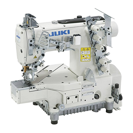
- Page 1 ® Semi-dry head, Cylinder-bed Top and Bottom Coverstitch Machine MF-7800D Series ENGINEER’S MANUAL 40084355 No.E387-00...
- Page 2 PREFACE This Engineer’s Manual is written for the technical personnel who are responsible for the service and maintenance of the machine. The Instruction Manual for these machines intended for the maintenance personnel and operators at an apparel factory contains operating instructions in detail. And this manual describes "Standard Adjustment", "Adjustment Procedures", "Results of Improper Adjustment", and other important information which are not covered by the Instruction Manual.
-
Page 3: Table Of Contents
1. SPECIFICATIONS....................1 2. CONFIGURATION OF THE MACHINE COMPONENTS ........2 3. MODEL NUMBERING SYSTEM ................3 (1) MF-7800D Series ........................3 (2) MF-7800D Series Thread trimmer..................4 4. MOTOR PULLEY AND BELT ................. 5 5. STANDARD ADJUSTMENT ................... 6 (1) Threading the machine head . - Page 4 8. DRAWING OF TABLE..................157 (1) Top mount type ........................157 (2) Half-sunk table ........................158 (3) Table for H21 ........................159 (4) Table for 7800D-E10 ......................160...
-
Page 5: Specifications
Looper mechanism Spherical rod drive method Lubricating system Forced lubrication method by gear pump Lubricating oil JUKI MACHINE OIL 18 (Equivalent to ISO VG18) Oil reservoir capacity Oil gauge lower line : 600 cm to upper line : 900 cm Installation... -
Page 6: Configuration Of The Machine Components
2. CONFIGURATION OF THE MACHINE COMPONENTS Presser spring regulator Oil gauge Rocking thread take-up Needle bar thread take-up cover Feed regulating knob Front cover Oil circulation identification window Eye guard cover Slide cover Oil hole cap Throat plate Needle bar thread take-up thread Micro-lifter Needle tip silicon oil lubricating unit receiver... -
Page 7: Model Numbering System
3. MODEL NUMBERING SYSTEM (1) MF-7800D Series Semi-dry head, cylinder-bed top and bottom coverstitch machine Applicable model : MF-7800D Series 10 11 12 13 14 15 16 17 18 19 20 21 M F 7 8 – 3 to 6... -
Page 8: Mf-7800D Series Thread Trimmer
(2) MF-7800D Series Thread trimmer Semi-dry head, cylinder-bed top and bottom coverstitch machine Applicable model : MF-7800D Series Thread trimmer 10 11 12 13 14 15 16 17 18 19 20 21 22 23 24 25 26 27 28 29 30 M F 7 8 –... -
Page 9: Motor Pulley And Belt
4. MOTOR PULLEY AND BELT MF-7800D Series Sewing speed of the 50Hz 60Hz machine (sti/min) Pulley size (mm) Belt size (inch) Pulley size (mm) Belt size (inch) 3,500 ø80 M-38 ø65 M-37 4,000 ø90 M-38 ø75 M-37 1 . The table shows the numbers when a 3-phase 2-pole 400 W clutch motor (1/2 HP) is used. -
Page 10: Standard Adjustment
5. STANDARD ADJUSTMENT (1) Threading the machine head Standard Adjustment 1. Threading for standard seam Broken lines when stretcher thread is used When covering thread is When using more When using less When covering thread is excessively loosened = stretchable thread stretchable thread excessively tense = When covering thread is... - Page 11 Adjustment Procedure Results of Improper Adjustment 1. When motion of thread is very rough, and stable seams can not be o When threading is not properly obtained, there are cases where the condition can be improved by performed, not only sewing trouble occurs, but also needle the following threading.
-
Page 12: Adjusting The Rocking Thread Take-Up
(2) Adjusting the rocking thread take-up Standard Adjustment 1. Length of the rocking thread take-up (1) Dimension A from the center of the shaft to the thread hole face of rocking thread take-up is the standard length of rocking thread take-up Unit : mm Dimension A Standard seams... - Page 13 Adjustment Procedure Results of Improper Adjustment 1. Length of the rocking thread take-up o When length of rocking thread (1) Loosen screws and move rocking thread take-up to the right take-up is lengthened, needle or left to adjust the length. thread is tightened.
-
Page 14: Adjusting The Position Of The Needle Thread Guide Rod
(3) Adjusting the position of the needle thread guide rod Standard Adjustment 1. Position of the needle thread guide rod (1) Dimensions of left needle A, middle needle B and right needle C from the top surface of needle thread guide base to the bottom ends of holes are the standard height of needle thread guide rods Unit : mm... - Page 15 Adjustment Procedure Results of Improper Adjustment o When needle thread guide rod 1. Loosen setscrews , adjust the height of respective needle thread is raised, needle thread is guide rods , and fix the rods with setscrews loosened. (Caution) 1. Move the lateral position of needle thread guide base o When needle thread guide rod fully to the right of slot.
-
Page 16: Adjusting The Position Of The Thread Receiver
(4) Adjusting the position of the thread receiver Standard Adjustment 1. Position of the needle bar thread take-up thread receiver (in case of standard seams) (1) It is the standard that the height of needle bar thread take-up thread receiver is in the position where the bottom end of thread hole to the center of needle bar thread take-up aligns with the top surface of needle... - Page 17 Adjustment Procedure Results of Improper Adjustment 1. Loosen setscrew and move needle bar thread take-up thread o When the needle bar thread receiver up or down to adjust the height. take-up thread receiver 2. When desired to make needle bar thread take-up thread receiver raised, loop becomes large.
-
Page 18: Adjusting The Position Of The Spreader Thread Guide And Spreader Thread Take-Up
(5) Adjusting the position of the spreader thread guide and spreader thread take-up Standard Adjustment 1. Relation of the position between spreader thread take-up and spreader thread guide is the standard when the top end of thread hole of spreader thread guide aligns with the bottom end of slot spreader thread take-up when spreader thread take-up... - Page 19 Adjustment Procedure Results of Improper Adjustment o When the relation of position 1. Loosen setscrews in spreader thread guide and adjust the between spreader thread take- position of spreader thread guide . (Spreader thread take-up and the spreader thread is fixed to rocking thread take-up and can not be adjusted in the guide is not proper, sewing height direction.)
-
Page 20: Adjusting The Spreader
(6) Adjusting the spreader Standard Adjustment 1. Height of the spreader It is the standard that the height from the top surface of throat plate to the bottom surface of spreader is 7.8 to 8.2 mm. 7.8 to 8.2mm 2. Longitudinal position of the spreader It is the standard that when spreader returns from the extreme left position to the right and top end thread hooking section reaches to the front of left needle, the clearance between the spreader and the left... - Page 21 Adjustment Procedure Results of Improper Adjustment 1. Adjusting the height of the spreader o Height of the spreader is improper, stitch skipping of spreader occurs. 2. Adjusting the longitudinal position of the spreader o Adjust the height in accordance Loosen setscrew and adjust the height and longitudinal position with the needle gauge.
- Page 22 (6) Adjusting the spreader Standard Adjustment 6. Adjustment figures of the spreader thread guide (1) It is the standard that the clearance provided between spreader and spreader thread guide is 0.4 to 1.0 mm. (2) It is the standard that the clearance provided between spreader thread guide and needle clamp thread guide is 0.8 to 1.2 mm.
- Page 23 Adjustment Procedure Results of Improper Adjustment 6. Spreader thread guide o When height or position of the (1) Adjust the height of spreader to 7.8 to 8.2 mm. Loosen setscrews spreader thread guide is im- in the spreader thread guide and adjust the clearance provided p r o p e r, s t i t c h s k i p p i n g o f between the top surface of spreader and spreader thread guide...
-
Page 24: Adjusting The Timing Relation Between The Looper And Needle Bar
(7) Adjusting the timing relation between the looper and needle bar Standard Adjustment 1. Timing relation between the looper and the needle bar (synchronization) It is the standard that dimension is the same as dimension when the needle bar goes up from the lower dead point, the blade point of looper passes the rear of needle, and the left end of right needle aligns with the blade point of looper, and when the needle bar comes down from the upper dead point, the blade point of looper passes the front of needle, and the right end of right needle aligns with the blade point of... - Page 25 Adjustment Procedure Results of Improper Adjustment o When the difference in timing 1. To adjust the timing relation between the needle and the looper, (going and returning) of looper is remove the top cover, loosen four setscrews in the sprocket and excessively large, stitch skipping turn upper pulley in the state that the sprocket is held.
-
Page 26: Returning Amount Of The Looper
(8) Returning amount of the looper Standard Adjustment 1. It is the standard that returning amount of looper from top end of looper to the center of needle bar is 5.9 mm regardless of the needle gauge when looper is in the extreme right position. 5.9mm 2. - Page 27 Adjustment Procedure Results of Improper Adjustment 1. Loosen setscrew in the looper holder and move looper holder o When the returning amount is to the right and left to adjust. large, loop of needle thread be- 2. After the adjustment, tighten setscrew in the looper holder.
-
Page 28: Height Of The Needle
(9) Height of the needle Standard Adjustment 1. It is the standard that the top end of needle eyelet of left needle aligns with the bottom end of looper when the top end of looper passes the rear of the needle from the extreme right position and protrudes from the left end of left needle by approximately 1 mm (Calculated value : 1.1 mm), dimension B. - Page 29 Adjustment Procedure Results of Improper Adjustment 1. Remove rubber cap in the face plate, loosen setscrew in the o When the height of the needle needle bar bracket and adjust the height of the needle bar. is excessively different, stitch 2.
-
Page 30: Locus And Longitudinal Motion Of The Looper
(10) Locus and longitudinal motion of the looper Standard Adjustment 1. It is the standard that the top end of left needle touches the position of 1/4 to 1/3 from the bottom face of the back of the looper when the looper returns from the extreme left position in the standard looper motion locus. - Page 31 Adjustment Procedure Results of Improper Adjustment o When the longitudinal motion of 1. Changing the longitudinal motion of the looper the looper is small, the rate that (1) Remove 10 setscrews in cover and remove cover needle touches the back of the The position where engraved marker line on looper driving arm looper is increased and blunt...
-
Page 32: Adjusting The Needle Guard
(11) Adjusting the needle guard Standard Adjustment 1. Standard position of the rear needle guard (1) Height of the rear needle guard It is the standard that the clearance provided between crest line A of rear needle guard the top end of right needle is 1.5 mm to 2 mm when top end of the looper comes from the extreme right position to the center of right needle. - Page 33 Adjustment Procedure Results of Improper Adjustment 1. Remove setscrews and remove needle cooler unit and cam cover 2. Adjust the height of rear needle guard with setscrew o When the clearance provided be- adjust the longitudinal position with setscrew tween rear needle guard the needle is large, stitch skip- ping, blunt blade point of the looper, or needle breakage will be...
- Page 34 (11) Adjusting the needle guard Standard Adjustment 2. Standard position of the front needle guard (1) Height of the front needle guard It is the standard position that the height of front needle guard is positioned higher by 3.3 ± 0.5 mm than rear needle guard (2) Clearance provided between the needle and the front needle guard It is the standard that the clearance provided between the needle and front needle guard...
- Page 35 Adjustment Procedure Results of Improper Adjustment 1. Height of the front needle guard o When the clearance provided between front needle guard (1) Adjust the height of front needle guard to the position where it is and the needle is larger, loop be- higher by 3.3 ±...
-
Page 36: Adjusting The Feed Dog
(12) Adjusting the feed dog Standard Adjustment 1. Height of the feed dog It is the standard that the height of feed dogs (main feed dog and differential feed dog ) is 1 ± 0.1 mm from the top surface of the throat plate when feed dogs are in the highest position. - Page 37 Adjustment Procedure Results of Improper Adjustment o When the position of the feed dog 1. Adjusting the height of the feed dog is high, stitch skipping, defective (1) Loosen setscrew in the differential feed dog and setscrew chain off, return of feed, etc. will the main feed dog, and adjust the height.
- Page 38 (12) Adjusting the feed dog Standard Adjustment 3. Lateral position of the feed dog It is the standard of the lateral position of the feed dog that the left and right clearances A of the feed dog in terms of the slots of the throat plate are parallel and equal. –...
- Page 39 Adjustment Procedure Results of Improper Adjustment o When the lateral position of the 3. Adjusting the lateral position of the feed dog rocking bars is incorrect, worn- (1) Loosen setscrew in rocking bar presser, right , and loosen out of throat plate and feed dog setscrews in rocking bar presser, left will be caused.
- Page 40 (12) Adjusting the feed dog Standard Adjustment 4. Longitudinal position of the feed dog (1) Position of the main feed dog : it is the standard that the position where the clearance from the edge of the slot of the throat plate to the front face of the main feed dog is 0.6 ± 0.2 mm at the position where the main feed dog travels to the extreme front position (operator’s side) when feed momentum is set to 3.6 mm (maximum).
- Page 41 Adjustment Procedure Results of Improper Adjustment o When the fixing position of the 4. Longitudinal position of the feed dog (condition : feed momentum main feed lever slips greatly out 3.6 mm (maximum)) of position, abnormal noise or (1) Remove the bed top cover. abrasion will be caused.
-
Page 42: Adjusting The Feed Relation
(13) Adjusting the feed relation Standard Adjustment 1. Changing the stitch length It is possible for the standard stitch length to adjust up to 0.9 to 3.6 mm. Turning feed adjust knob clockwise increases the stitch length and turning it counterclockwise decreases the stitch length. - Page 43 Adjustment Procedure Results of Improper Adjustment o When the stitch length is set to 1. When making the stitch length more than 3.6 mm, loosen setscrew more than 3.6 mm, the contact of the feed adjustment stopper pin, turn feed adjust knob of main feed dog, differential feed clockwise, and adjust the stitch length.
-
Page 44: Adjusting The Presser Foot
(14) Adjusting the presser foot Standard Adjustment 1. Height of the presser foot Height of the presser foot has to be the position the presser foot does not come in contact with other components at the position where lifter lever is lowered and comes in contact with height adjustment screw Dimension A... - Page 45 Adjustment Procedure Results of Improper Adjustment o When the position of the presser 1. Adjusting the height of the presser foot foot is too high, it comes in con- Loosen adjustment nut . Lower lifter lever , adjust height tact with the spreader, and break- adjustment screw , and fix nut at the position where the presser...
-
Page 46: Adjusting The Micro-Lifter
(15) Adjusting the micro-lifter Standard Adjustment 1. Micro-lifter Adjust the micro-lifter in accordance with sewing conditions for use. Major applicable process 1. When twist occurs in the hemming bottom process. 2. When tape is twisted in collecting. Down – 42 –... - Page 47 Adjustment Procedure Results of Improper Adjustment 1. Adjusting the micro-lifter (1) When micro-lifter knob is turned counterclockwise, micro-lifter stopper lower and comes in contact with presser lifting lever Then the presser foot goes up. Adjust the height accordance with the sewing conditions. (2) When micro-lifter knob is turned clockwise, micro-lifter stopper is raised and comes in contact with presser lifting lever...
-
Page 48: Adjusting The Looper Thread Cam
(16) Adjusting the looper thread cam Standard Adjustment 1. Adjust so that thread comes off from the highest place of looper thread cam when needles come down and the top end of left needle aligns with the bottom surface of looper . - Page 49 Adjustment Procedure Results of Improper Adjustment o When the position of looper 1. Loosen setscrews in the looper thread cam and adjust while thread cam slips greatly out checking that looper thread comes off from the periphery of the looper thread cam.
-
Page 50: With Regard To Lubrication
Lubricating oil has been taken out at the time of delivery. Be sure to supply lubricating oil before using the sewing machine for the first time. Oil used : JUKI MACHINE OIL 18 (Caution) Do not use oil addition agent since deterioration of lubricating oil or machine trouble will be caused. - Page 51 Adjustment Procedure Results of Improper Adjustment 1. Inspection and replacement o In case oil cannot be observed Loosen setscrews in the oil filter cap and remove oil filter cap from oil circulation identification Draw out oil filter to inspect it. When it is clogged with dust, replace window even when the sew- it with a new one.
- Page 52 (17) With regard to lubrication Standard Adjustment 3. Oiling No oiling 4. Replacing the lubricating oil – 48 –...
- Page 53 4. Replacing the lubricating oil In case of the new sewing machine, replace the lubricating oil (JUKI MACHINE OIL 18) with new one after using it for approximately one month. Then replace the lubricating oil every six months.
-
Page 54: Adjusting And Setting Sc-510
(18) Adjusting and setting SC-510 1. When SC-510 is used, install the motor referring to the Instruction Manual for SC-510. 2. Installation of the synchronizer 1) Synchronizer can be installed by the method be- low. 2) Using two setscrews , mount synchronizer fixing plate on the sewing machine. - Page 55 3. Synchronizer adjustments The synchronizer can be adjusted in the procedures specified below. WARNING : To protect against possible injury to hands or fingers due to abrupt start of the machine during performing adjustment, perform the adjustment of the stop position under the function setting mode. Loosen screw and remove cover Turn disk...
- Page 56 4. Setting procedure of the machine head Refer to “3-3 Setting for functions of SC-510” in the INSTRUCTION MANUAL for SC-510, and call the function setting No. 95. The type of machine head can be selected by press- ing switch (switch After determining the type of machine head, by pressing switch...
- Page 57 5. Machine head list Machine head Type Contents Sewing speed set at Max. sewing of display the time of delivery speed (sti/min) from factory (sti/min) — MF Semi-dry (MF-7700D/7800D) MF.d 4000 4000 MF (4 needles) MF.S3 3200 4200 MF Roller MF.S1 4000 5000...
-
Page 59: Mf-7800D-H21
(20) MF-7800D-H21 Hemming type (with left hand fabric trimmer) 1) Specifications Model MF-7800D-H21 Class name Covering stitch machine with left hand fabric trimmer Application Hemming of knit and jersey products Max. sewing speed 4,000 sti/min (At the time of intermittent operation 3-needle 5.6 mm, 6.4 mm Needle gauge... - Page 60 2) Adjustment Standard Adjustment 1. Adjusting the upper knife pressure 2. Adjusting the lateral position of the lower knife – 56 –...
- Page 61 Adjustment Procedure Results of Improper Adjustment 1. Adjusting the upper knife pressure (1) Loosen setscrews in thrust collar , fix section A, and move thrust collar to right and left to adjust the knife pressure. It is standard adjustment that the clearance between thrust collar and metal is 10 mm.
- Page 62 Standard Adjustment 3. Adjustment procedure of engagement amount of knives 0.5mm 4. Replacement procedure of upper knife and lower knife – 58 –...
- Page 63 Adjustment Procedure Results of Improper Adjustment 3. Adjustment procedure of engagement amount of knives (1) Loosen setscrew in the upper knife holder and adjust so that the engagement amount of the top end of the upper knife and lower knife is approximately 0.5 mm when upper knife is in its lowest position.
- Page 64 Standard Adjustment 5. Adjusting the upper knife stroke – 60 –...
- Page 65 Adjustment Procedure Results of Improper Adjustment (1) Loosen setscrews in the waste cloth pipe and remove waste cloth pipe (2) Remove setscrews in the installing base cover, and remove installing base cover (3) Loosen lock nut of the adjustment pin and move adjustment pin up or down to adjust the stroke of the upper knife.
- Page 66 MEMO – 62 –...
-
Page 67: Mf-7800D-E10
(21) MF-7800D-E10 For Elastic band attaching (with right hand fabric trimmer) 1) Specifications Model MF-7800D-E10 Class name Right-hand fabric trimmer for pre-closed elastic attaching with tension roller Application Pre-closed waist elastic attaching of men’s brief, trunks, etc. (Waist elastic width up to 40 mm) Max. - Page 68 2) Adjustment of knife and presser Standard Adjustment 1. Adjustment procedure of engagement amount of knives 0.5mm 2. Adjustment procedure of the knife pressure 3. Adjustment procedure of knife cutting position – 64 –...
- Page 69 Adjustment Procedure Results of Improper Adjustment 1. Adjustment procedure of engagement amount of knives (1) When adjusting the engagement, perform the work after confirming regarding the height of fixed knife that the upper surface of the fixed knife is flush with the upper surface of the throat plate or the former is installed slightly lower than the latter.
- Page 70 Standard Adjustment 4. Replacement procedure of fabric trimmer and fixed knife 5. Adjustment procedure of cloth guide – 66 –...
- Page 71 Adjustment Procedure Results of Improper Adjustment 4. Replacement procedure of fabric trimmer and fixed knife (1) Remove setscrew and remove the old fabric trimmer (2) Press arrow mark plane of new fabric trimmer to the machined plane of knife holder , and tighten it with setscrew (3) When replacing fixed knife , loosen setscrew...
- Page 72 Standard Adjustment 6. Adjustment procedure of front-up amount of the presser foot 7. Adjustment procedure of the position of the tape guide – 68 –...
- Page 73 Adjustment Procedure Results of Improper Adjustment 6. Adjustment procedure of front-up amount of the presser foot (1) When sewing a thick rubber sheet or the like together, fabric can be smoothly fed by raising the front of presser foot (2) Loosen nut , turn setscrew to the right (clockwise), and raise the front presser foot...
- Page 74 3) Adjusting procedure of the position of the tension roller Standard Adjustment 1. Adjusting the lateral position Elastic band A : Contact 2. Adjusting the vertical position – 70 –...
- Page 75 Adjustment Procedure Results of Improper Adjustment 1. Adjusting the lateral position Adjust so that the right-hand end of the elastic band meets the left- hand side of collar of the front roller and collar of the intermediate roller when putting straight the elastic band on the front roller.
- Page 76 Standard Adjustment 3. Adjusting the longitudinal position 4. Adjusting the position of the bottom roller 5. Adjusting the position of the rear roller – 72 –...
- Page 77 Adjustment Procedure Results of Improper Adjustment 3. Adjusting the longitudinal position (1) Loosen knobs of slide shaft , and adjust the longitudinal position. (2) After adjusting the position, tighten knobs 4. Adjusting the position of the bottom roller (1) Adjusting the lateral position Loosen three screws , adjust the bottom roller so that the elastic band is put straight, and tighten three screws...
- Page 78 4) Adjusting procedure of the position of the tape guide base Standard Adjustment 1. Adjusting the position of the guide roller Elastic band C : Approx. 30 mm 2. Adjusting the elastic guide D : Approx. 41 mm ° E : Approx. 60 –...
- Page 79 Adjustment Procedure Results of Improper Adjustment 1. Adjusting the position of the guide roller (1) Adjusting the vertical position Loosen screw , and adjust so that the top surface of support bracket is lower by 0.5 mm that the top surface of bracket Then tighten screw (2) Adjusting the longitudinal position Loosen lever...
- Page 80 Standard Adjustment 3. Adjusting the elastic band presser plate 0.5mm A : Approx. 7.5 mm – 76 –...
- Page 81 Adjustment Procedure Results of Improper Adjustment (1) Adjusting the lateral position Loosen screw and screw , and adjust presser shaft so that the clearance between presser and knife is 0.5 mm. Then, tighten screw and screw (2) Adjusting the vertical position Loosen screw , and adjust bracket so that Size A from the top...
- Page 82 Standard Adjustment 4. Adjusting the position of lever 5. Adjusting the position of stopper 6. Adjusting the presser plate pressure – 78 –...
- Page 83 Adjustment Procedure Results of Improper Adjustment 4. Adjusting the position of lever Loosen screw , and adjust so that the clearance between lever and the top surface of presser is 3 mm. Then tighten screw 5. Adjusting the position of stopper Loosen screw , and adjust stopper to the position before it...
- Page 84 MEMO – 80 –...
-
Page 85: Mf-7800D-Ut25/Ut24
(22) MF-7800D-UT25/UT24 Pneumatic thread trimming device Compressed air/Air consumption UT25 Compressed air Air consumption Top and bottom thread Air-blow type wiper MC35 /min (ANR) trimmer/Auto-lifter MC36 Compressed air/Air consumption UT24 Air consumption Compressed air Bottom thread Air-blow type wiper MC35 /min (ANR) trimmer/Auto-lifter MC36... - Page 86 Installation and setting SC-500 UT25 Standard Adjustment 1. Installing procedure of the synchronizer 2. Installing procedure of the resistor pack (asm.) 3. Installing procedure of the exclusive cord for MF SC-500 – 82 –...
- Page 87 UT25 Adjustment Procedure Results of Improper Adjustment Connect M50 motor and SC-500 control box, referring to “II. SET-UP” of the Instruction Manual for SC-500. 1. Installing procedure of the synchronizer (1) Using two setscrews , mount synchronizer fixing plate on the sewing machine.
- Page 88 2) Change of the setting UT25 Standard Adjustment Setting of SC-500 FL ON : Auto-lifter device becomes effective. FL OFF : Auto-lifter function does not work. (Standard at the time of delivery) (Similarly, the presser foot is not automatically lifted when programmed stitching is completed.) (Caution) 1.
- Page 89 UT25 Adjustment Procedure Results of Improper Adjustment In order to utilize the setting of SC-500 for MF-7800D, the operations below are necessary. (1) Selection of the auto-lifter function When the auto-lifter device is attached, this function makes the function of auto-lifter work. 1) Turn ON the power switch while pressing switch inside the control box.
- Page 90 3) Adjusting the synchronizer (Adjusting procedure of both SC-500 and SC-510 is common.) UT25 Standard Adjustment 1. Adjusting DOWN position – 86 –...
- Page 91 UT25 Adjustment Procedure Results of Improper Adjustment (1) Loosen screw and remove cover (2) Turn disk on this side by hand, and adjust the adjusting mark “B” of disk in the rear to edge of disk (3) Temporarily tighten the synchronizer to the lower main shaft handwheel with screw (4) When the power is turned ON, the sewing machine turns approximately by one half and stops.
- Page 92 4) Installation and setting SC-510 UT25 Standard Adjustment 1. Installing procedure For the details of installation of SC-510, refer to the Instruction Manual for SC-510. SC-510 – 88 –...
- Page 93 UT25 Adjustment Procedure Results of Improper Adjustment (1) Connect M51 motor and SC-510 control box, referring to “II. SET- UP” of the Instruction Manual for SC-510. (2) Installing procedure of the synchronizer Using two setscrews , mount synchronizer fixing plate on the sewing machine.
- Page 94 UT25 Standard Adjustment 2. Change of the setting Type A Type B 3. Setting of SC-510 – 90 –...
- Page 95 UT25 Adjustment Procedure Results of Improper Adjustment 2. Change of the setting As so the control box of SC-510, there are two types. Type A is displayed in one of them, and type B is displayed in the other when the power is turned ON.
- Page 96 UT25 Standard Adjustment 4. Confirmation of the automatic presser lifting function 5. Selecting procedure of the automatic presser lifting function 6. Method of auto-lifter device selection Solenoid drive display (+33V) Air drive display (+24V) – 92 –...
- Page 97 UT25 Adjustment Procedure Results of Improper Adjustment (4) After selecting MF of the type of machine head, press ( ) switch and ( ) switch . Then the step advances to 96 or 93, and the setting is automatically changed over to the setting adaptable to the type of machine head.
- Page 98 5) Piping of the thread trimmer device UT25 Standard Adjustment 1. Piping drawing with the needle thread trimmer. 2. Piping drawing for air blow. – 94 –...
- Page 99 UT25 Adjustment Procedure Results of Improper Adjustment Adjusting the air regulator Air hose (1) Insert the air hose to air regulator (2) Use the air pressure at 0.4 to 0.5 MPa (4 to 5 kgf/cm (3) Draw up regulator knob and turn regulator knob until the air pressure pointer attains 0.4 to 0.5 MPa.
- Page 100 6) Adjusting the looper thread trimmer mechanism UT25 Standard Adjustment 1. Adjusting the thread trimmer air cylinder 18mm 2. Adjusting the Lower knife To align 197mm – 96 –...
- Page 101 UT25 Adjustment Procedure Results of Improper Adjustment 1. Adjusting the thread trimmer air cylinder (1) Stroke of air cylinder is 18 mm. (2) When adjusting the stroke, loosen setscrew of collar and move collar to the right or left to adjust. 2.
- Page 102 UT25 Standard Adjustment 3. Engaging the knives and adjusting the clamp spring 3.2mm 0.5mm 4. Adjusting the position of clamp pressure adjusting spring Section A 0.5 to 1mm 5. Adjusting the pressure of clamp spring – 98 –...
- Page 103 UT25 Adjustment Procedure Results of Improper Adjustment 3. Engaging the knives and adjusting the clamp spring (1) Loosen screws , and adjust the position of upper knife so that the engagement of the upper knife with the lower knife is 0.5 mm when lower knife moves to the extreme right.
- Page 104 UT25 Standard Adjustment 6. Initial position of the lower thread trimmer mechanism To align 7. Adjusting the stopper 6 to 7mm 8. Adjusting the height of the lower knife 0 to 0.1mm – 100 –...
- Page 105 UT25 Adjustment Procedure Results of Improper Adjustment 6. Initial position of the lower thread trimmer mechanism Adjust so that the right-hand edge of lower knife holder aligns with the right-hand edge of thread trimmer installing base when air cylinder moves to the extreme left position. (1) Remove pin screw (2) When turning the screw section of adjustment link clockwise,...
- Page 106 UT25 Standard Adjustment 9. Adjusting the longitudinal position of the blade point of lower knife Blade point of lower knife is in the center of thickness of looper 12mm 10. Adjusting the lower knife holder guide To lightly come in contact with each other 11.Adjusting the thread trimmer sensor –...
- Page 107 UT25 Adjustment Procedure Results of Improper Adjustment 9. Adjusting the longitudinal position of the blade point of lower knife (1) Bring the needle bar to its highest position. (2) Adjust so that the blade point of lower knife is in the center of the thickness of looper when the clearance between the right-hand edge of looper...
- Page 108 UT25 Standard Adjustment 12.Adjusting the speed of lower thread trimmer Clearance between click section and thread tension disk : 0 to -0.5mm (5 positions) 33 to 36mm 0 to –0.5mm (Click section enters thread tension disk – 104 –...
- Page 109 UT25 Adjustment Procedure Results of Improper Adjustment Speed of the lower thread trimmer device can be changed with speed o When the protruding speed of controllers of air cylinder lower knife is slow, thread trim- (1) When you desire to change the protruding speed of lower knife, ming failure will be caused.
- Page 110 7) Adjusting the top covering thread trimmer mechanism UT25 Standard Adjustment 1. Adjustment of needle thread trimmer 0.5mm Top covering thread 2. Adjusting the speed of moving knife – 106 –...
- Page 111 UT25 Adjustment Procedure Results of Improper Adjustment 1. Adjustment of needle thread trimmer (1) Adjusting the engagement of knives 1) Adjust so that the engagement of fixed knife with moving knife is 0.5 mm. 2) When adjusting the engagement, loosen setscrews and move knife holder up or down to adjust.
- Page 112 1) Adjusting the air-blow wiper UT24 Standard Adjustment 1. Installing the air-blow wiper 2. Adjusting the air-blow wiper : To solenoid valve : To air blow – 108 –...
- Page 113 UT24 Adjustment Procedure Results of Improper Adjustment 1. Installing the air-blow wiper (1) When using air-blow wiper , remove the top covering thread trimmer device. (2) Tighten air-blow wiper with setscrews Perform piping referring to “Air piping drawing”. 2. Adjusting the air-blow wiper Adjust the air-blow position of air-blow wiper (1) Adjust so that the air outlet of air-blow wiper is positioned in the...
- Page 114 MEMO – 110 –...
-
Page 115: Mf-7800D-Ut22
(23) MF-7800D-UT22 Electromagnetic type thread trimming device UT22 (Electromagnetic type top and bottom thread trimming device) – 111 –... - Page 116 1) Installing SC-500 UT22 Standard Adjustment 1. Installing procedure of the synchronizer 2. Installing procedure of the resistor pack (asm.) 3. Installing procedure of the exclusive cord for MF SC-500 – 112 –...
- Page 117 UT22 Adjustment Procedure Results of Improper Adjustment 1. Installing procedure of the synchronizer (1) Using two setscrews , mount synchronizer fixing plate on the sewing machine. Then, install synchronizer on it. (2) Fix a cord of synchronizer to synchronizer fixing plate means of cable clip band .
- Page 118 2) Installing SC-510 UT22 Standard Adjustment 1. Wiring SC-510 – 114 –...
- Page 119 UT22 Adjustment Procedure Results of Improper Adjustment Installing procedure of the exclusive cord for MF Connect the exclusive cords for MF to the respective designated con- nectors as follows. • Synchronizer cord → CN33 • Thread trimmer sensor cord → CN42 •...
- Page 120 3) Adjusting the looper thread trimmer mechanism UT22 Standard Adjustment 1. Adjusting the looper thread trimmer solenoid 18mm 18mm – 116 –...
- Page 121 UT22 Adjustment Procedure Results of Improper Adjustment (1) Stroke of looper thread trimmer solenoid is 18 mm. (2) When adjusting the stroke, loosen setscrew of collar and move collar to the right or left to adjust. (3) After adjusting the stroke, loosen screw from the lower side, and move collar to the left and right to adjust so that the stroke...
- Page 122 4) Adjusting the top covering thread trimmer mechanism UT22 Standard Adjustment 、 0.5mm 18mm Top covering thread – 118 –...
- Page 123 UT22 Adjustment Procedure Results of Improper Adjustment 1. Adjusting the engagement of knife (1) Adjust so that the engagement of fixed knife with moving knife is 0.5 mm. (2) When adjusting the engagement, loosen setscrew and adjust lever 2. Adjusting the moving knife stroke (1) Adjust so that the stroke of moving knife is 18 mm.
- Page 124 MEMO – 120 –...
-
Page 125: Mc-35/Mc-36
(24) MC-35/MC-36 Pneumatic cloth chip suction device MC-35 MC-36 Model MC-35 MC-36 Name Pneumatic cloth chip suction device with a solenoid Pneumatic cloth chip suction device with a pedal valve air switch connecting rod air switch Applicable MF-7800D-H21 and MF-7800D-E10 provided with the MF-7800D-H21 and MF-7800D-E10 machines control box (SC-510) Major... - Page 126 1) Installation and adjustment of MC-35/MC-36 MC-36 Standard Adjustment 1. Installing the connecting rod MC-36 2. Adjusting the connecting rod air valve MC-36 Light contact – 122 –...
- Page 127 MC-36 Adjustment Procedure Results of Improper Adjustment 1. Installing the connecting rod MC-36 (1) Taking care of the vertical direction of the connecting rod, fix the top end of the rod on motor lever using the screw of ball joint , and fix the bottom end of the rod on pedal lever using the screw of...
- Page 128 MC-36 Standard Adjustment 3. Assembling the cloth chip and chain-off thread suction device Rear of the frame 550mm Rear of the frame 4. Connecting the flexible hose – 124 –...
- Page 129 MC-36 Adjustment Procedure Results of Improper Adjustment 3. Assembling the cloth chip and chain-off thread suction device (1) Fix two tube clips to mounting plate with screws and fitting lock nuts (2) Fix mounting plate with (tube clip) installing wood screws that tube clips face the operator’s side at the bottom face of the table while satisfying the dimensions of the table shown in the figure.
- Page 130 MC-36 Standard Adjustment 5. Adjusting the suction force 6. Installing the waste bag 30 mm Stand Stand Drawing of the table (rear) Front of the frame Switch Drawer – 126 –...
- Page 131 MC-36 Adjustment Procedure Results of Improper Adjustment 5. Adjusting the suction force (1) When A is turned clockwise, the suction force is decreased. (2) For the mechanical valve of MC-36, the suction force can be adjusted by turning B with a screwdriver or the like. 6.
- Page 132 MC-35 Standard Adjustment 7. Piping the air components Piping diagram for the MC-35 Piping diagram for the MC-36 Air-regulator 8. Cabling for MC-35/SC-510 SC-510 – 128 –...
- Page 133 MC-35 Adjustment Procedure Results of Improper Adjustment 7. Piping the air components Refer to the piping diagram shown for piping the air components. (Caution) The air tube is slightly too long. Cut it to an appropriate length before connecting it. 8.
- Page 134 MEMO – 130 –...
-
Page 135: Pl11
(25) PL11 Cloth puller PL11 Specifications Model PL11 (Flat roller) Class name Cloth puller device Max. sewing speed 4,000 sti/min Manual lever PL11 : 10.3 mm When lift of presser foot is 4 mm PL11 : 8.0 mm Lift roller Presser lifter When lift of presser foot is 5 mm PL11 : 8.7 mm... - Page 136 PL11 Standard Adjustment Adjusting the roller presser pressure Adjusting the feed amount of the roller – 132 –...
- Page 137 PL11 Adjustment Procedure Results of Improper Adjustment 1. Adjusting the roller presser pressure (1) Loosen nut and turn presser spring regulator to the right (clockwise) when increasing the presser pressure. (2) Turn presser spring regulator to the left (counterclockwise) when decreasing the presser pressure.
- Page 138 PL11 Standard Adjustment 3. Adjusting the roller presser lifter 0.5mm 4. Assembling the rear roller asm. – 134 –...
- Page 139 PL11 Adjustment Procedure Results of Improper Adjustment 3. Adjusting the roller presser lifter (1) Adjust with two screws so that the clearance between presser lifter lever link, short and hinge screw is 0.5 mm when performing the presser lifting in the state that the top roller is lowered. 4.
- Page 140 PL11 Standard Adjustment 5. Adjusting the clutch tension spring 6. Grease lubrication system – 136 –...
- Page 141 PL11 Adjustment Procedure Results of Improper Adjustment 5. Adjusting the clutch tension spring (1) Adjustment is performed with clutch tension spring so that the top roller does not overrun at high-speed rotation. (2) When performing the adjustment, loosen can nut , and turn nut to the right (clockwise) to increase the spring pressure.
- Page 142 PL11 Standard Adjustment 7. Feed timing of the roller – 138 –...
- Page 143 PL11 Adjustment Procedure Results of Improper Adjustment 7. Feed timing of the roller (1) The standard position of the roller is the position when notch A of joint aligns with notch B of the puller eccentric cam . When changing the feed timing, loosen two setscrews in puller eccentric to adjust.
-
Page 144: Other Cautions
Wet section in the forced lubrication chamber (2) Application of appropriate grease 1. Where lubrication is needed in any parts other than the lubricating sections, the appropriate grease (Juki Grease A; 23640204, Juki Grease B; 40013640) is already applied. Never use any other type of grease. - Page 145 2. There is a grease groove inside the metal of needle bar crank rod Asm. (No. 2). When the needle bar connection (No. 4) is pulled out, fill this groove section with Juki Grease B. 3. There is a lead groove inside the presser lifting shaft Asm. (No. 46). When the presser lifting shaft Asm.
-
Page 146: Adhesives Application Spots
2 Parts related to spreader (Caution) There is a grease groove inside the spreader longitudinal metal (No. 28). When the spreader longitudinal shaft is pulled out, fill this groove section with Juki Grease B. (3) Adhesives application spots • Needle clamp After degreasing the threaded part of the needle clamp, apply “Lock Tight 242”... - Page 156 One chain stitch by right needle One chain stitch by middle needle One chain stitch by left needle Right needle thread miss Middle needle thread miss – 152 –...
-
Page 161: Drawing Of Table
Installing position of stopper for drawed (On the reverse side) 2 x ø3.4, on the bottom surface, depth 10 (Drill a hole at the time of set-up) JUKI logotype Measure detailed drawing (2:1) Type: Helvetics Reg. Condensed Condensed: Voided letters Y-Y (3-places) Thickness: 1.5... -
Page 162: Half-Sunk Table
(On the reverse side) 4-10.5 hole, depth 26, spot facing depth 3.5 2 x ø3.4, on the bottom surface, depth 10 (Drill a hole at the time of set-up) JUKI logotype Measure detailed drawing (2:1) Type: Helvetics Reg. Condensed Condensed: Voided letters Thickness: 1.5... -
Page 163: Table For H21
Installing position of stopper for drawed (On the reverse side) 2 x ø3.4, on the bottom surface, depth 10 (Drill a hole at the time of set-up) JUKI logotype Measure detailed drawing (2:1) Type: Helvetics Reg. Condensed Condensed: Voided letters Y-Y (3-places) Thickness: 1.5... -
Page 164: Table For 7800D-E10
(Bracket mounting holes) 2 x ø3.8 on the (bottom) surface, depth 10 (Drill a hole at the time of set-up). (Push button switch mounting position) JUKI logotype Front Y-Y (3-places) Part No. : 40024948 – 160 –... - Page 165 ISO14001 : 2004 REG.NO.JSAE389 CM001 Juki Corporation operates an environmental management system to promote and conduct the following as the company engages in the research, development, design, sales, distribution,and maintenance of industrial sewing machines, household sewing machines, industrial robots, etc., and in the provision of sales and maintenance services...