
Related Manuals for Ricoh Aficio SP 100SF


Summary of Contents for Ricoh Aficio SP 100SF
- Page 1 Model ME-P1/MF1_ww Machine Code: M101/M102/M103 Field Service Manual 26 December, 2011...
-
Page 3: Safety, Symbols, Trademarks
Safety, Symbols, Trademarks Conventions Commonly Used Icons for Replacements and Adjustments Symbol What it means Binding screw (shoulder hexagonal head) Binding screw (round flathead) Black screw (heavy, fusing unit, TCRU) Bushing C-ring Connector E-ring FFC (Flat Film Connector) FFC (Flat Film Connector) Gear Harness clamp Harness clamp (metal: fusing unit) -
Page 4: Paper Feed: Sef/Lef
Symbol What it means Standoff Stud screw Tapping screw (wide threads for plastic) Timing belt Paper Feed: SEF/LEF The notations "SEF" and "LEF" describe the direction of paper feed. The arrows indicate the direction of paper feed. In this manual "Main Scan" means "Horizontal" and "Sub Scan" means "Vertical", both relative to the direction of paper feed. -
Page 5: Machine Names
ME-P1 M101 Aficio SP 100SU ME-MF1a M102 Aficio SP 100SF ME-MF1b M103 The abbreviated notations in the second column above (not used in these service manuals) are used in the operating instructions to distinguish the machine models: • P: Printer only •... -
Page 6: Key Presses
Key Presses Symbol What It Means The names of machine operation panel keys and PC keyboard keys are enclosed in [Key] square brackets. This means to press one of the arrow keys to move the menu selector up/down ( ) or Select left/right ( ) to the menu selection you want and then press [OK] on the machine... -
Page 7: General Safety Instructions
General Safety Instructions For your safety, please read this manual carefully before you use this product. Keep this manual handy for future reference. Safety Information Always obey the following safety precautions when using this product. Safety During Operation In this manual, the following important symbols and notations are used. Switches and Symbols Where symbols are used on or near switches on machines for Europe and other areas, the meaning of each symbol conforms with IEC60417. -
Page 8: Before Installation, Maintenance
Before Installation, Maintenance Shipping and Moving the Machine • Work carefully when lifting or moving the machine. If the machine is heavy, two or more customer engineers may be required to prevent injuries (muscle strains, spinal injuries, etc.) or damage to the machine if it is dropped or tipped over. -
Page 9: Special Tools
Special Tools • Use only standard tools approved for machine maintenance. • For special adjustments, use only the special tools and lubricants described in the service manual. Using tools incorrectly, or using tools that could damage parts, could damage the machine or cause injuries. -
Page 10: Power Plug And Power Cord
• Switch the machine off, unplug it, and allow it to cool before doing preventive maintenance. To avoid fire or explosion, never use an organic cleaner near any part that generates heat. • Wash your hands thoroughly after cleaning parts with an organic cleaner to prevent contamination of food, drinks, etc. -
Page 11: Points To Confirm With Operators
• Toner thrown into a fire can ignite or explode and cause serious injury. At the work site always carefully wrap used toner and toner cartridges with plastic bags to avoid spillage before disposal or removal. • Always dispose of used items (developer, toner, toner cartridges, OPC drums, AIO units, etc.) in accordance with the local laws and regulations regarding the disposal of such items. -
Page 12: Handling And Storing Toner
• If toner is inhaled, immediately gargle with large amounts of cold water and move to a well ventilated location. If there are signs of irritation or other problems, seek medical attention. • If toner gets on the skin, wash immediately with soap and cold running water. •... -
Page 13: Safety Instructions For The Machine
Safety Instructions for the Machine Prevention of Physical Injury 1. Before disassembling or assembling parts of the machine and peripherals, make sure that the machine and peripheral power cords are unplugged. 2. The plug should be near the machine and easily accessible. 3. -
Page 14: Safety And Ecological Notes For Disposal
Safety and Ecological Notes for Disposal 1. Never incinerate toner bottles or used toner. Toner dust may ignite suddenly when exposed to an open flame. 2. Dispose of used toner, developer, and organic photoconductors in accordance with local regulations. (These are non-toxic supplies.) 3. -
Page 15: Trademarks
Trademarks ® ® • Microsoft , and Windows are registered trademarks of Microsoft Corporation in the United States and /or other countries. ® • PostScript is a registered trademark of Adobe Systems, Incorporated. ® • PCL is a registered trademark of Hewlett-Packard Company. ®... -
Page 16: Table Of Contents
TABLE OF CONTENTS Safety, Symbols, Trademarks..........................1 Conventions..............................1 Commonly Used Icons for Replacements and Adjustments...............1 Paper Feed: SEF/LEF..........................2 Smart Organizing Monitor........................2 Machine Names............................3 AIO (All In One) Cartridge........................3 Key Presses.............................4 RoHS Compliance..........................4 Warnings, Cautions, Notes...........................4 General Safety Instructions..........................5 Responsibilities of the Customer Engineer....................5 Customer Engineer..........................5 Reference Material for Maintenance....................5 Before Installation, Maintenance........................6... - Page 17 Health Safety Conditions........................11 Observance of Electrical Safety Standards..................11 Safety and Ecological Notes for Disposal..................12 Laser Safety..............................12 Trademarks..............................13 1. Product Information Specifications..............................21 New Product Information..........................22 Series Machines Compared........................22 General Differences..........................22 Common AIO............................23 Feature Summary............................23 General Features..........................23 Duplex Printing............................24 Important Points to Remember......................24 General Configuration..........................25 M101 Configuration..........................25 M102 Configuration..........................26...
- Page 18 Machine Level..............................36 Space Requirements............................36 Moving the Machine...........................37 Smart Organizing Monitor..........................37 Important Features............................38 3. Preventive Maintenance Cleaning the Machine.............................39 Before Cleaning............................39 Routine Cleaning............................39 4. Replacement and Adjustments Before You Begin.............................41 Precautions..............................41 Special Tools..............................41 Printing the Test Page and Reports......................41 Basic Procedures..............................43 Before You Begin............................43 M101 Covers..............................43 M101 AIO............................43...
- Page 19 Platen Cover, Flatbed Scanner Unit....................55 M103 Covers, Flatbed Unit, ADF......................60 Original Feed Tray..........................60 AIO...............................60 Output Tray............................61 Front Cover............................62 Right Cover............................62 Left Cover.............................64 Left Hinge.............................66 Rear Cover............................66 ADF/Flatbed Unit..........................66 Removing the Fusing Unit..........................71 Utilities and Maintenance...........................75 Operation Panels.............................77 M101 Operation Panel..........................77 M102 Operation Panel..........................78 M103 Operation Panel..........................79 Laser Unit................................81...
- Page 20 Pickup Roller Solenoid..........................104 Switches................................106 Safety Switch.............................106 Output Tray Switch............................108 Fusing Unit..............................111 Separating Fusing Unit..........................111 Exit Roller..............................113 Pressure Roller............................114 Hot Roller, Fusing Lamp..........................116 Thermostat..............................118 Thermistor..............................119 Ground Plate..............................120 Boards................................121 M101 Main Board...........................121 M102 Main Board...........................123 M103 Main Board...........................127 After Replacing the Main Board......................130 M103 Fax Board............................132 M103 Fax Speaker..........................132 PSU................................134...
- Page 21 6. Troubleshooting Utilities................................159 Overview of Utilities..........................159 Smart Organizing Monitor........................159 Initial Screen............................160 Status Tab Change Button........................161 Job Log Tab............................162 User Tool Tab ...........................164 Printer Configuration Screen ......................164 System Tab ............................165 Printer Tab ............................167 Copy Tab (M102/M103 Only) ....................168 Fax Tab (M103 Only) ........................169 Smart Organizing Monitor Service Mode....................170 What Is Service Mode? ........................170 Service Mode Screen........................170...
- Page 22 Image Problems.............................211 Overview..............................211 Printing the Test Page..........................212 Dark Lines in Halftone Areas........................213 Common Problems............................215 All Models..............................215 M101, M102............................216 M103.................................216 7. Energy Saving Energy Save..............................219 Energy Save Modes..........................219 Energy Save Operation........................219 Timer Settings and Return to Standby Mode .................220 Recommendations..........................220 Paper Save..............................221 Effectiveness of Duplex/Combine Functions...................221 1.
-
Page 23: Product Information
1. Product Information Specifications See "Appendices" for the following information: • Before You Read These Specifications • General Specifications • Printer Specifications (M101, M102, M103) • Copier Specifications (M102, M103) • Scanner Specifications (M102, M103) • Fax Specifications (M103 Only) •... -
Page 24: New Product Information
Model No. Aficio SP 100 M101 Aficio SP 100SU M102 Aficio SP 100SF M103 The abbreviated notations in the second column above are used in the operating instructions to distinguish the machine models: • P: Printer only • TiO: Three-in-1 (printer, copier, scanner) •... -
Page 25: Common Aio
New Product Information Common AIO The AIO (All In One) cartridge (or print cartridge) in the center of the machine is permanently sealed around the main elements of the printing mechanisms: (1) drum charge unit, (2) drum, (3) development unit, (4) tone supply unit, (5) cleaning blade, and (6) waste toner collection tank. •... -
Page 26: Duplex Printing
1. Product Information Standard Features M101 M102 M103 Output Tray (10 sheets) Paper Tray (50 sheets) Platen (book mode scanning) The following features are not supported by these machines: • Bulk paper feed unit (only one small tray is available) •... -
Page 27: General Configuration
New Product Information • User Tool. Only the M103 has a [User Tool] button which opens the User Tool menu settings used to configure the machine. The Service Mode of the Smart Organizing Monitor is used to configure all three machines. (The User Tool menus on the M103 are duplicated in the Service Mode, so either feature can be used to configure the M103.) •... -
Page 28: M102 Configuration
1. Product Information M102 Configuration 1 Operation Panel Holds the keys and 2-digit display for printer operation. 2 Platen Covers the exposure glass. 3 Paper Tray Holds 50 sheets of paper for continuous feed. 4 Exposure Glass Place sheets here, one by one for copying. 5 Paper Tray Cover Raise to extend the paper tray, and lower after pushing the paper tray down into the machine. -
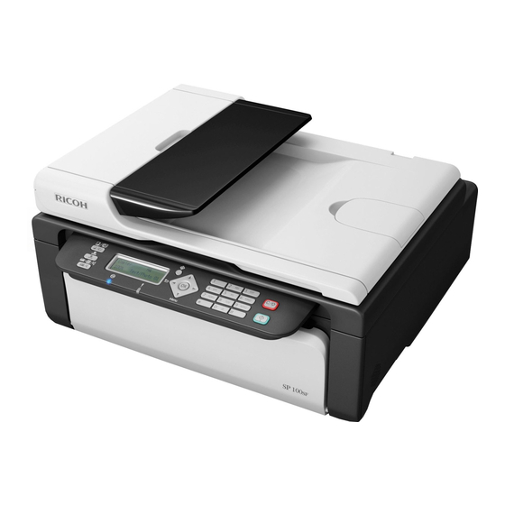
Page 29: M103 Configuration
New Product Information M103 Configuration 1 Operation Panel Holds the keys and 2-digit display for printer operation. 2 ADF Cover Opens for removal of originals that jam during scanning. 3 Original Tray Holds originals for scanning. 4 Original Tray Extension Extends for scanning long originals. -
Page 30: Operation Panels
1. Product Information Holds up to 15 originals for continuous scanning. Raises and lowers with the flatbed scanner below for installation of the AIO, removing paper jams, and placing an original on the exposure glass for book- mode scanning. 12 Original Output Tray Holds up to 15 originals after they have been scanned. -
Page 31: M102 Operation Panel
New Product Information Name Reset Key Force Feed Key Power Indicator Alert Indicator M102 Operation Panel [A]: CHN, [B]: NA, [C]: EU Name Name Display (LCD) Cancel/Stop Key Copy Number Key Start Key Density Indicator Power Indicator Density Key Alert Indicator... -
Page 32: M103 Operation Panel
1. Product Information Name Name ID Copy Key M103 Operation Panel [A]: CHN, [B]: NA, [C]: EU Name Key Name Copy/Fax Key ID Copy/On Hook Key Speed Dial Key Power Indicator User Tools Key Display Screen (LCD) OK key Alert Indicator Cancel/Stop Key Scroll Keys Start Key... -
Page 33: Alert Leds
New Product Information Alert LEDs Power LED The Power LED remains OFF while the machine is turned off. The Power LED lights and remains ON: • After the machine is turned on and enters the Ready mode • While the machine is in energy save mode The Power LED FLASHES at 1 sec. -
Page 34: Overview
1. Product Information Overview Paper Path Paper Tray Hot Roller Pickup Roller Pressure Roller Feed Rollers Exit Sensor Registration Sensor Exit Rollers Drum Output Tray Transfer Roller When paper passes through the machine: • Paper (up to 50 sheets) is loaded in the paper tray (1). The pickup roller (2), driven by the main motor and engaged by the bypass solenoid, starts to rotate while a cam on the feed roller (3) (also driven by the main motor) raises the bottom plate of the tray against the pickup roller above. -
Page 35: Drive Layout
New Product Information • The exit sensor (9) detects the leading edge and trailing edge of the paper. The sensor will trigger a jam alert if the leading and trailing edge do not pass within the time prescribed for the length of the paper (determined by the selected paper size). -
Page 36: Image Writing
1. Product Information Image Writing Registration Sensor Polygon Mirror Lenses, Mirrors Drum Transfer Roller The registration sensor (1) detects the leading edge of the paper fed from the feed rollers and triggers the laser unit to fire the laser. The polygon mirror (2) shoots the laser through lenses and mirrors (3) and onto the surface of the drum (4). -
Page 37: Installation
2. Installation Installation Requirements Installation Procedure For instructions on unpacking the machine, installing the print cartridge, connection and software installation, please refer to the operating instructions Quick Installation Guide. Environment Temperature 15°C to 25°C (59°F to 77°F) Humidity 30% to 70% rH 1. -
Page 38: Power Requirement
2. Installation 4. Do not put the machine in areas with sudden temperature changes. This includes: • Areas directly exposed to cool air from air conditioning • Areas directly exposed to heat from a heating system. 5. Do not put the machine in areas exposed to corrosive gas. 6. -
Page 39: Moving The Machine
Installation Requirements There should be enough space at the front so the output tray can be opened and closed. Moving the Machine The machine is light, but be careful when you move it: • Always lift the printer by the inset handles on the left and right sides. •... -
Page 40: Important Features
2. Installation • Printing reports and test pages The Smart Organizing Monitor is provided with the machine on a CD-ROM and must be installed together with the printer driver. Important Features Here are some important features you should remember: • The AIO units for these machines have no ID chips attached to the AIO units. •... -
Page 41: Preventive Maintenance
3. Preventive Maintenance Cleaning the Machine There are no PM parts for this machine. This section describes how the machine should be cleaned. Before Cleaning • Always switch the machine off and unplug it before cleaning. • At least once a year, disconnect the power cable and clean the plug. Accumulated dust causes a fire hazard. - Page 42 3. Preventive Maintenance 2. Clean the exposure glass and white plate above the exposure glass of the M102/M103 with a soft damp cloth, and then wipe it with a dry cloth. 3. Clean the scanning glass of the M103 with a soft damp cloth, and then wipe it with a dry cloth. •...
-
Page 43: Replacement And Adjustments
4. Replacement and Adjustments Before You Begin Precautions • To prevent electrical shock, always switch the machine off and unplug it from its power source. • Allow the machine to cool for at least 10 minutes. This allows the fusing unit to cool and also allows time for the polygon mirror inside the laser unit to stop rotating. - Page 44 4. Replacement and Adjustments Report Procedure [Stop/Reset] > [1] [0] [7] > [Start] > "Fax Maintenance" > Error Log History List "Report" > "Error Log History List" [User Tools] > "Fax Features" > "Report Print Set" > "Fax Fax Journal Journal"...
-
Page 45: Basic Procedures
Basic Procedures Basic Procedures Before You Begin This section describes the procedures that the service technician should know before servicing the machine. Most of the parts of the machines in this series are identical and interchangeable. However, please note that the main boards of these machines are not the same. •... -
Page 46: Output Tray
4. Replacement and Adjustments 3. Place the AIO on a flat clean surface as shown above so the drum is not exposed to light. Output Tray 1. Lower the output tray. 2. Press in on both ends to release the pegs on the left and right from their holes and remove the tray. •... -
Page 47: Front Cover
Basic Procedures Front Cover 1. Lower the output tray and remove the front cover ( x2). Top Cover Preparation • Remove front cover (See above) 1. Open the paper tray cover. 2. Release the rear tabs [A] on the left and right. 3. -
Page 48: Maintenance Cover
4. Replacement and Adjustments 4. Use the tip of a small screw driver to release the tabs at [A], [B], [C] ( 5. Open the top cover [A] to the right. 6. Disconnect the operation panel [B] , and then remove the cover ( x1). -
Page 49: Right Cover
Basic Procedures • The top cover can be removed easily with the maintenance cover attached. • Do not remove the maintenance cover unless it needs to be replaced. Repeatedly removing and attaching the maintenance cover can weaken or break the fragile tabs. 1. -
Page 50: Left Cover
4. Replacement and Adjustments • There are three tabs on the bottom. • There is one tab on the back. 2. Lift the machine slightly. 3. Release the tab on the back ( x1). 4. Release the tabs on the bottom ( x3). -
Page 51: Rear Cover
Basic Procedures 2. Locate the triangle marks that show you where the tab releases are located on the bottom. 3. Release the tabs on the bottom ( x3). 4. Separate the cover from the left side of the machine. Rear Cover The rear cover does not require removal unless the PSU requires replacement ( p.134 "PSU") -
Page 52: M102 Covers, Platen Cover, Flatbed Unit
4. Replacement and Adjustments M102 Covers, Platen Cover, Flatbed Unit Platen 1. Raise the platen and then lift it straight up to remove it. 1. Raise the flatbed unit [A]. 2. Grip the AIO [B] by its handle and pull it out of the machine. -
Page 53: Output Tray
Basic Procedures 3. Place the AIO on a flat clean surface as shown above so the drum is not exposed to light. Output Tray • You do not need to remove the output tray in order to remove the front cover. •... -
Page 54: Front Cover
4. Replacement and Adjustments Front Cover 1. Raise the flatbed unit [A]. 2. Lower the output tray [B]. 3. Disconnect the front cover [C]( x2). 4. Remove the front cover. Right Cover... - Page 55 Basic Procedures 1. Remove the screw on top of the right cover ( x1). 2. Locate the triangle marks that show you where the tab releases are located on the bottom. 3. Release the tabs on the top [A] and rear [B] ( x3).
-
Page 56: Left Cover
4. Replacement and Adjustments Left Cover Preparation • Raise the flatbed unit • Remove the AIO • Remove the front cover 1. Remove the screw on top of the left cover ( x1). 2. At the top of the hinge, look at the head of the cotter pin [A]. The flat side of the head shows you where the two split ends of the pin are located. -
Page 57: Rear Cover
Basic Procedures • The pin is split into four sections but only two sides protrude to lock and release the pin. 4. At the triangle markers, release the tabs: [A] Front ( [B] Rear ( [C] Bottom ( Rear Cover The rear cover does not require removal unless the PSU requires replacement ( p.134 "PSU") Platen Cover, Flatbed Scanner Unit... - Page 58 4. Replacement and Adjustments • AIO • Front Cover • Right Cover • Left Cover 1. Disconnect the flat cables ( 2. Disconnect harness [A] ( x1). 3. Pull the harness out of harness guide [B].
- Page 59 Basic Procedures 4. Pull the flat cable out of the ferrite plate [A], and then remove the harness guide. 5. Remove the right hinge pin ( x1). 6. Remove the left hinge pin ( x1).
- Page 60 4. Replacement and Adjustments 7. The hinge pins are identical. Either pin can be re-installed on either side. 8. Lift the flatbed unit off the top of the machine.
- Page 61 Basic Procedures 9. Use the tip of a small screwdriver to disconnect the platen cover tabs and then remove the cover. Re-installation 1. Before you re-install the flatbed unit on top of the machine, insert the wide flat cable through the ferrite plate.
-
Page 62: M103 Covers, Flatbed Unit, Adf
4. Replacement and Adjustments M103 Covers, Flatbed Unit, ADF Original Feed Tray 1. Press in and release the pegs on each end of the tray. 2. Remove the tray. 1. Raise the top of the machine [A] (the ADF and flatbed unit together). 2. -
Page 63: Output Tray
Basic Procedures 3. Place the AIO on a flat clean surface as shown above so the drum is not exposed to light. Output Tray • You do not need to remove the output tray in order to remove the front cover. •... -
Page 64: Front Cover
4. Replacement and Adjustments Front Cover 1. Raise the ADF and flatbed unit [A] together. 2. Lower the output tray [B]. 3. Disconnect the front cover [C]( x2). 4. Remove the front cover. Right Cover Preparation • Raise the flatbed unit and ADF together •... - Page 65 Basic Procedures 1. Remove the screw on top of the right cover ( x1). 2. Locate the triangle marks that show you where the tab releases are located on the bottom. 3. Release the tabs at the back [A] and front [B] ( x2).
-
Page 66: Left Cover
4. Replacement and Adjustments Left Cover Preparation • Raise the flatbed unit and ADF together • Remove the AIO • Remove the front cover 1. Remove the screw on top of the left cover ( x1). - Page 67 Basic Procedures 2. At the top of the hinge, look at the head of the cotter pin [A]. The flat side of the head shows you where the two split ends of the pin are located. 3. With your fingers or the tips of a pair of radio pliers compress the split ends [B] of the pin, push it to the left, and then remove it.
-
Page 68: Left Hinge
4. Replacement and Adjustments Left Hinge The right hinge does not require removal unless it must be replaced. Preparation • Remove the right cover 1. Use a pair of radio pliers to remove the spring [A] ( x1). 2. Use the tip of a small screwdriver to release the guides [B] ( x2). - Page 69 Basic Procedures 1. Disconnect the bottom connectors on the right ( x3). 2. Disconnect the ground wire ( x1). 3. Disconnect the FFC's [A] ( x3). 4. Disconnect the harness from the harness guide [B].
- Page 70 4. Replacement and Adjustments 5. Disconnect the harness guide [A] ( x1). 6. Pull the flat cable out of the ferrite plate [B], and then remove the harness guide. 7. Remove the right hinge pin ( x1). 8. Remove the left hinge pin ( x1).
- Page 71 Basic Procedures 9. The hinge pins are identical. Either pin can be re-installed on either side. 10. Left the flatbed unit and ADF off the top of the machine together. 11. Lay flatbed unit and ADF on a flat surface.
- Page 72 4. Replacement and Adjustments 12. Use the tip of a small screw driver to release the hinges ( x2). 13. Pull the harnesses through the rear right corner of the flatbed unit.
-
Page 73: Removing The Fusing Unit
Basic Procedures Re-installation 1. Before you re-install the flatbed unit on top of the machine, insert the wide flat cable through the ferrite plate. • It is very difficult to thread this flat cable through the plate after setting the flatbed unit and ADF on top of the machine. - Page 74 4. Replacement and Adjustments • Left cover M102 p.50 "M102 Covers, Platen Cover, Flatbed Unit") • AIO • Front cover • Left cover M103 p.60 "M103 Covers, Flatbed Unit, ADF") • AIO • Front cover • Left cover 1. Release the power cord. 2.
- Page 75 Basic Procedures 5. Free the harness ( x1). 6. At the front, disconnect the fusing unit ( x4).
- Page 76 4. Replacement and Adjustments 7. Disconnect the thermistor harness ( x1). 8. Disconnect the exit sensor ( x1). 9. Separate the exit sensor harness from the fusing unit across the front [A] and up the right side [B].
-
Page 77: Utilities And Maintenance
Basic Procedures 10. Pull the fusing unit [A] partially out of the front of the machine. 11. Pull the fusing unit harness through the hole [B]. 12. Pull the fusing unit out of the machine and lay it on a flat surface. Utilities and Maintenance This is a quick summary of the utilities that are available for machine servicing. - Page 78 4. Replacement and Adjustments 1. To start Fax Maintenance (M103 Only) 1. Make sure the machine is in the Ready mode. 2. Press [Stop/Reset] and then press [1] > [0] > [7]. 3. Press and hold down [Start[. 2. To start Fax Test (M103 Only) 1.
-
Page 79: Operation Panels
Operation Panels Operation Panels M101 Operation Panel Preparation • Remove top cover ( p.43 "M101 Covers") 1. Lay the top cover on a flat surface. 2. Remove the operation panel PCB ( x1). -
Page 80: M102 Operation Panel
4. Replacement and Adjustments M102 Operation Panel 1. Raise the platen and then lift it straight up to remove it. 2. Press firmly on the top edge of the operation panel and push toward the front of the machine until you hear it click and release. -
Page 81: M103 Operation Panel
Operation Panels 3. Lift the operation panel straight up to disconnect the hooks at three points. 4. Turn the operation panel over, and then disconnect the flat cable ( x1). M103 Operation Panel... - Page 82 4. Replacement and Adjustments 1. Raise the ADF and flatbed unit. 2. Remove left screw [A] and right screw [B] ( x2). 3. While supporting the operation panel with one hand, remove the center screw ( x1). 4. Lower the operation panel slightly and disconnect it ( x1).
-
Page 83: Laser Unit
Laser Unit Laser Unit Removing the Laser Unit • There are no serviceable parts inside the laser unit. Never attempt to disassemble the laser unit and then reinstall it in the machine. Preparation M101 p.43 "M101 Covers") • AIO • Front, top cover •... - Page 84 4. Replacement and Adjustments 1. If you are servicing the M102 or M103, you must release the tab on the right [A] and remove the laser unit cover ( x1). • The M101 does not have this white cover. • The procedure below from Step 2 applies to all three machines. 2.
-
Page 85: After Replacing The Laser Unit
Laser Unit 3. Pull the ground wire and connectors [A] through the frame. 4. Disconnect the laser unit assembly ( x4). 5. Remove the laser unit and lay it on a flat surface. After Replacing the Laser Unit After replacing the laser unit, print the Test Page and check the position of the image area on the page. 1. - Page 86 4. Replacement and Adjustments 2. Click the User Tool tab (1), open the List/Test pull-down list (2), and then click [Print]. The Test Page prints. 3. Check the margins of the image area to see the width of the margins are satisfactory. Margin Width (mm) Left...
- Page 87 Laser Unit 5. Adjust the Factory Registration settings to adjust the margins. • Horizontal. Shifts the image left or right to adjust the left/margins. • Vertical. Shifts the image up or down to adjust the top/bottom margins.
-
Page 88: Paper Feed And Exit
4. Replacement and Adjustments Paper Feed and Exit This section describes how to remove these items: • Pickup Roller • Friction Pad • Paper Feed Roller • Image Transfer Roller • Exit Roller Preparation These items must be removed before doing any procedure in this section. Do this now before going to any other part of this section. -
Page 89: Pickup Roller
Paper Feed and Exit p.60 "M103 Covers, Flatbed Unit, ADF") Front cover Top cover Right cover Left cover Flatbed unit, ADF Laser unit p.81 "Removing the Laser Unit") Pickup Roller 1. Set the machine so you an see the bottom plate. 2. - Page 90 4. Replacement and Adjustments 4. Disconnect the feed guide: [A] At the top ( [B] On the bottom of the machine ( 5. At the top, disconnect the arm pegs on the left [A] and on the right [B]. 6. Lift the feed guide out of the machine.
- Page 91 Paper Feed and Exit 7. Release the arm pegs on the left and right, and then remove the paper tray. 8. The pickup roller [A] in the center of the paper path is permanently attached to its shaft. 9. On the right, disconnect the gear train [B] ( x3).
- Page 92 4. Replacement and Adjustments 11. Remove the pickup solenoid and plate ( 12. Pinch the hook lock/release on one-way clutch and pull the clutch off the shaft ( x1).
- Page 93 Paper Feed and Exit • The one-way clutch comes off as one piece. • The hook lock/release locks the one-way clutch in place when it is re-installed. 13. Inside the machine on the left, grip the end of the pickup roller [A]. 14.
-
Page 94: Friction Pad
4. Replacement and Adjustments 17. The pickup roller and shaft are replaced as one unit (the roller is permanently attached to the shaft). Friction Pad 1. Press the pinch releases on each side ( x2). 2. Rotate and raise the pad. 3. -
Page 95: Paper Feed Roller
Paper Feed and Exit Paper Feed Roller Preparation • Remove the pickup roller ( p.87 "Pickup Roller") 1. On the right end of the roller [A] lift the end of the shaft out of its groove. 2. Lift the roller out of the bracket at [B]. 3. - Page 96 4. Replacement and Adjustments 1. Before you remove the transfer roller: • The collar on the left end of the roller [A] is black. • The collar on the right end of the roller [B] is white. • The transfer roller must be installed the same way, with the black collar on the left and white collar on the right.
- Page 97 Paper Feed and Exit 4. Remove the spring from the left end [A] and right end [B] to prevent the springs from getting lost. • If you are replacing the transfer roller, save these springs. New springs may not be provided with the new transfer roller.
-
Page 98: Exit Roller
4. Replacement and Adjustments 2. After re-installing the transfer roller, press and release the transfer roller several times to confirm that the roller bounces up and down evenly. • If the center or either end of the roller does not bounce up and down freely, this means that one or both springs at the ends of the roller are not installed correctly. -
Page 99: Sensors
Sensors Sensors Registration Sensor Preparation • Remove the AIO. 1. Raise the machine so you can see the bottom. 2. Disconnect the bottom plate and remove it ( x1). 3. Locate the registration sensor on the bottom of the machine. -
Page 100: Exit Sensor
4. Replacement and Adjustments 4. Disconnect the sensor and remove it ( x3). Exit Sensor Preparation • Remove the front cover ( x2). 1. On the front of the fusing unit [A], disconnect the exit sensor [B] ( x1). 2. Remover the sensor ( x3). -
Page 101: Main Motor
Main Motor Main Motor Removing the Main Motor Preparation M101 • AIO p.43 "M101 Covers") • Front cover • Right cover M102 • AIO p.50 "M102 Covers, Platen Cover, Flatbed Unit") • Front cover • Right cover M103 • AIO p.60 "M103 Covers, Flatbed Unit, ADF") •... - Page 102 4. Replacement and Adjustments 3. Remove the gear train and lay it on a flat surface as shown above to prevent the gears from falling off. 4. Free the harnesses [A] ( x2). 5. Disconnect the motor mount [B] ( x3).
- Page 103 Main Motor 8. Remove gear [A] and then gear [B]. 9. Disconnect gear [A] ( x1). 10. After the e-ring is removed, the gears [B] will spring up slightly. 11. Remove gear [A] and then gear [B].
- Page 104 4. Replacement and Adjustments 12. Remove gear [A] and spring [B]. 13. Remove the screws ( x3). 14. Lift the motor mount plate off the motor.
-
Page 105: Reinstalling The Main Motor
Main Motor 15. Turn the motor over. Reinstalling the Main Motor 1. Match boss [A] with the hole [B] on the motor plate. This aligns the holes correctly for re-attachment of the motor to the motor mount plate. -
Page 106: Solenoid
4. Replacement and Adjustments Solenoid Pickup Roller Solenoid Preparation • Remove right cover p.43 "M101 Covers") p.50 "M102 Covers, Platen Cover, Flatbed Unit") p.60 "M103 Covers, Flatbed Unit, ADF") 1. Free the solenoid harness [A] ( x1). 2. Remove screw [B] ( x1). - Page 107 Solenoid...
-
Page 108: Switches
4. Replacement and Adjustments Switches Safety Switch • NA model has the two safety switches (Replacement procedure is as follows). Preparation M101 p.43 "M101 Covers") • AIO • Front cover • Left cover M102 p.50 "M102 Covers, Platen Cover, Flatbed Unit") •... - Page 109 Switches 1. If you are servicing the M103, you must move the speaker so you can access the breaker switch. • Release the tabs at the top of the speaker mounting plate ( x2). • Move the speaker slightly to the right (you do not need to remove it). 2.
-
Page 110: Output Tray Switch
4. Replacement and Adjustments Output Tray Switch Preparation M101 p.43 "M101 Covers") • Front cover • Top cover • Left cover M102 p.50 "M102 Covers, Platen Cover, Flatbed Unit") • Front cover • Right cover M103 p.60 "M103 Covers, Flatbed Unit, ADF") •... - Page 111 Switches 1. The output tray push-switch is mounted at [A] and connected to the main board at [B]. 2. Disconnect the harness at [A] and [B] ( x2). 3. Release the harness ( x1).
- Page 112 4. Replacement and Adjustments 4. With finger tips or a pair of radio pliers, depress the top and bottom of the switch release at [A]. 5. Pull out the switch [B].
-
Page 113: Fusing Unit
Fusing Unit Fusing Unit This section describes how to remove these items: • Exit Roller • Pressure Roller • Fusing Lamp • Thermostat • Thermistor Separating Fusing Unit Preparation • Remove the fusing unit ( p.71) 1. Two strong springs on either side of fusing unit [A] left and [B] right keep the soft pressure roller compressed against the hot roller. - Page 114 4. Replacement and Adjustments 2. Use tip of a pair or radio pliers to remove the spring [A] on the right end of the fusing unit ( x1). 3. Remove the pressure arm [B]. 4. Repeat Steps 2 and 3 to remove the spring and pressure arm on he left end of the fusing unit ( x1).
-
Page 115: Exit Roller
Fusing Unit 7. Small springs hold the three stripper pawls in place against the hot roller. • Removing the pawl springs is recommended to prevent the springs or pawls from falling off and becoming lost. Exit Roller Preparation • Remove the fusing unit ( p.71) •... -
Page 116: Pressure Roller
4. Replacement and Adjustments 3. Turn the exit roller [A] until you see the flat side of the roller shaft facing up. 4. Pull the roller [B] straight up to remove it from its cradle. 5. Remove the rollers and roller shaft. (The rollers are permanently attached to the shaft.) Pressure Roller Preparation •... - Page 117 Fusing Unit • 1. Hold the pressure roller on both ends, and then lift it out of the bottom half of the separated fusing unit. 2. Lay the roller on a flat clean surface. • Avoid touching the surface of the pressure roller with your fingers or bare hands. If the roller requires cleaning, wipe the surface with a clean dry cloth.
-
Page 118: Hot Roller, Fusing Lamp
4. Replacement and Adjustments Hot Roller, Fusing Lamp Preparation • Remove the fusing unit ( p.71) • Separate the top and bottom halves of the fusing unit ( p.111 "Separating Fusing Unit") • 1. On the right end of the top half of the fusing unit, remove screw [A] ( x1). - Page 119 Fusing Unit 5. Lift both ends of the hot roller and remove it. • Avoid touching the surface of the hot roller with your fingers or bare hands. • If the roller requires cleaning, wipe the surface with a clean dry cloth. 6.
-
Page 120: Thermostat
4. Replacement and Adjustments 7. Lay the fusing lamp on a clean flat surface. • Avoid touching the surface of the fusing lamp with your fingers or bare hands. The oil from fingerprints or hand smudges can cause the surface of the fusing lamp to heat unevenly. •... -
Page 121: Thermistor
Fusing Unit • Always replace a blown thermostat with a new one. • Never attempt to reset a blown thermostat by manipulating the edges of the black cover with a screw driver. • Resetting a thermostat manually could cause a failure to detect overheating in the fusing unit and cause a fire hazard. -
Page 122: Ground Plate
4. Replacement and Adjustments Ground Plate 1. Note the correct position for the ground plate before re-installation. -
Page 123: Boards
Boards Boards M101 Main Board Preparation ( p.43 "M101 Covers") • Front cover • Top cover • Right cover 1. Disconnect board at the top ( x5). 2. Disconnect board on the left and bottom edges ( x6). • The socket at [A] is empty. Nothing is disconnected or reconnected here. - Page 124 4. Replacement and Adjustments 3. Disconnect and remove the board ( x5). Re-installation...
-
Page 125: M102 Main Board
Boards 1. When you re-install the board, be sure to re-connect the ground wire at the upper left corner of the main board. 2. If the main board has been replaced, be sure to do the procedures for after replacing a main board.( p.130 "After Replacing the Main Board") M102 Main Board... - Page 126 4. Replacement and Adjustments 2. Disconnect the flat cables at the upper right corner ( x2). 3. Disconnect the center harness ( 4. Above the board, disconnect the center harness from the harness guide.
- Page 127 Boards 5. Disconnect the lower left corner of the board ( x4). 6. Disconnect the upper right corner of the board ( x6). 7. Disconnect the main board ( x6).
- Page 128 4. Replacement and Adjustments 8. Remove the center harness bracket. 9. Remove the board. Re-installation...
-
Page 129: M103 Main Board
Boards 1. When you re-install the board, be sure to re-connect the ground wire at the upper left corner of the main board. 2. If the main board has been replaced, be sure to do the procedures for after replacing a main board. - Page 130 4. Replacement and Adjustments 2. Disconnect speaker harness [A] ( x1). 3. Open clamps [B] ( x2). 4. Disconnect lower right connectors [C] (x3). 5. Remove the ground screw and flat connectors ( x3). 6. On the top left corner of the board, remove the ground screw and connectors ( x5).
- Page 131 Boards 7. On the left side and bottom left edge of the board, disconnect the connectors ( x5). 8. Disconnect the bottom of the center brace and remove it ( x1). 9. Remove the remaining screws ( x3).
-
Page 132: After Replacing The Main Board
4. Replacement and Adjustments 10. Remove the board. Re-installation 1. When you re-install the board, be sure to re-connect the ground wires at the upper left corner and center of the main board. 2. If the main board has been replaced, be sure to do the procedures for after replacing a main board. - Page 133 Boards 2. Enter the service mode to display the Service Mode screen. 3. Do these settings on the service mode screen. Setting Comment Fuser SC Detect Signals a fatal error after three consecutive jams in the fusing unit. Serial No. Serial number of the machine.
-
Page 134: M103 Fax Board
4. Replacement and Adjustments M103 Fax Board The fax board is behind the main board. Preparation • Remove the M103 Main Board ( p.127 "M103 Main Board") 1. Disconnect and remove the fax board ( x3). • The screw at [A] is a wide-thread tapping screw (for plastic). Make sure that you re-fasten it at this position. - Page 135 Boards 1. Disconnect the speaker harness ( x1). 2. Disconnect and remove the speaker ( x2).
-
Page 136: Psu
4. Replacement and Adjustments Preparation M101 • Front cover p.43 "M101 Covers") • Right cover M102 • Front cover p.50 "M102 Covers, Platen Cover, Flatbed Unit") • Right cover M103 • Front cover p.60 "M103 Covers, Flatbed Unit, ADF") • Right cover 1. - Page 137 Boards 2. Disconnect the rear cover on the right ( x2). • If you are servicing the M103, you do not need to remove the clamp [A]...
- Page 138 4. Replacement and Adjustments 3. Remove the base of the power cord [A] from its mount. 4. Disconnect both connectors [A] ( x2). 5. Remove the screw [B]. 6. Pull the rear cover a short distance away from the back of the machine, and then pull the harness through the hole at the corner of the machine.
- Page 139 Boards 7. Lay the rear cover on a flat surface. 8. Disconnect the PSU ( x6). 9. Remove the PSU.
-
Page 140: Hvps
4. Replacement and Adjustments HVPS Preparation M101 • Front cover p.43 "M101 Covers") • Top cover • Left cover M102 • Front cover p.50 "M102 Covers, Platen Cover, Flatbed Unit") • Top cover • Right cover • Left cover • Platen cover •... - Page 141 Boards • Right cover • Left cover • Flatbed unit, ADF 1. The HVPS is in contact with four spring-loaded terminal heads behind the board. (These contacts are from the AIO.) 2. Remove the base of the power cord [A] from its mount. 3.
- Page 142 4. Replacement and Adjustments 5. Free the harness at [A] ( 6. Pull that harness out of the harness guide [B]. 7. Disconnect the board ( x1). 8. Remove the harness guide ( x2).
- Page 143 Boards 9. Press the tab release and remove the board ( x1). AIO Terminals...
- Page 144 4. Replacement and Adjustments There are four AIO springs but only three terminal nodes' • Points (1), (2), (3) have terminal nodes [A] on the end of the springs. • Point (4) consists of a spring only. Re-installation 1. The empty spring is re-attached at [A], and then the other springs [B] with the terminal nodes are inserted in the other holes.
- Page 145 Boards 2. When you re-install the board, make sure that the edge tabs [A] are inserted into the bottom slots. If the board is not inserted correctly, you will not be able to re-attach the harness guide [B] (the holes will not align correctly).
-
Page 146: Flatbed Scanner
4. Replacement and Adjustments Flatbed Scanner Separating the Flatbed Units The procedures for separating the top and bottom halves of the flatbed unit are different for the M102 and M103. • Follow the appropriate procedure below to separate the top and bottom of the flatbed unit. •... - Page 147 Flatbed Scanner 3. Disconnect the bottom plate ( x6). 4. Disconnect the hooks where the edge plate was removed. The top and bottom halves of the flatbed unit are now disconnected. 5. While holding the unit together with your hands on both sides, turn the unit over so the exposure glass is facing up.
-
Page 148: Flatbed Scanner (M103)
4. Replacement and Adjustments Flatbed Scanner (M103) Preparation • Front cover p.60 "M103 Covers, Flatbed Unit, ADF") • Right cover • Left cover • Flatbed Unit, ADF 1. Lay the flatbed unit on a flat surface with the exposure glass down. 2. - Page 149 Flatbed Scanner 1. Separate both ends of the CIS from the cradles. 2. Disconnect the CIS ( x1).
-
Page 150: Scanner Motor
4. Replacement and Adjustments Scanner Motor Preparation • Separate flatbed unit ( p.144) 1. Compress both ends of the spring [A] to relieve pressure on the scanning belt. 2. Remove the belt from the pulley [B] ( x1). - Page 151 Flatbed Scanner 3. Disconnect the scanning belt from the bottom of the CIS unit, and then lay the CIS aside (you do not need to disconnect the CIS) ( x1). 4. Disconnect the timing belt from the scanner motor pulley ( x1).
- Page 152 4. Replacement and Adjustments 6. Remove scanner motor bracket [A] and set it aside. 7. Pull the end of the harness through the hole [B]. 8. Disconnect the harness from the harness guide [C] and at [D] ( 9. Remove the motor and harness.
- Page 153 Flatbed Scanner 10. Disconnect the motor from the bracket ( x2). 11. Separate the motor and bracket. 12. Remove the gear clips ( x2).
- Page 154 4. Replacement and Adjustments 13. Remove gears [A] and [B]. Re-installation 1. When you re-attach the motor to the bracket, position the motor as shown above before fastening the screws.
-
Page 155: Adf (M103 Only)
ADF (M103 only) ADF (M103 only) There are no serviceable parts in the ADF. If the ADF malfunctions replace it. ( p.60 "M103 Covers, Flatbed Unit, ADF") - Page 156 4. Replacement and Adjustments...
-
Page 157: System Maintenance Reference
5. System Maintenance Reference Firmware Update The machine firmware can be updated with packages downloaded from a Web site. The firmware update procedure is described in the Operating Instructions and can be performed by the operator. Before Updating the Firmware RTB 10b Before you update the firmware: Important notes... - Page 158 5. System Maintenance Reference 4. Open the List/Test drop-down list, select Configuration Page, and then click [Print]. 5. The Configuration Prints the current Firmware Version number. 6. Click the [User Tools] tab, and then click [Printer Configuration].
- Page 159 Firmware Update 7. Click [Printer Firmware Update]. 8. Click [OK]. 9. Specify the location of the DWN file, and then click [Open].
- Page 160 5. System Maintenance Reference 10. A message will alert you if you select the wrong file. 11. After selecting the correct file, a message confirms that firmware update has completed 12. Cycle the machine off/on to initialize the new firmware. 13.
-
Page 161: Troubleshooting
6. Troubleshooting Utilities Overview of Utilities There are five utilities for setting and servicing these machines, but only three are used for all the machines. Function Start From M101 M102 M103 Fax Maintenance Operation Panel Fax Test Operation Panel Engine Maintenance Service Mode Counter Information Error History... -
Page 162: Initial Screen
6. Troubleshooting Initial Screen Image area. The image area on the top left, displays the image of the connected machine. Message area. The message area on the top right, displays the current status of the machine (Ready, Energy Saver 1, etc.) Status tab and area. -
Page 163: Status Tab Change Button
Utilities • When the progress bar appears blank with two asterisks to the right as shown above, the Toner End Option in User Tools is set for "Continue Printing". The machine does not count toner consumption, does not issue a toner near-end alert, and does not issue a toner end alert. The machine will keep printing until all the toner is used in the AIO. -
Page 164: Job Log Tab
6. Troubleshooting Name Size Letter 8.5 x 11 in. 5 1/2"x 8 1/2" Executive 7 1/4" x 10 1/2" B5 JIS 182 x 257 mm B6 JIS 128 x 182 mm 197 x 273 mm 195 x 270 mm 184 x 260 mm Configure the actual size of the paper with the Custom Paper Size Custom Paper Size settings on the Printer tab of the Printer Configuration screen. - Page 165 Utilities User Name. The name of the user who logged on and executed the job File Name. The name of the printed document. Page(s). The number of pages printed from the document. Start Date. Date and time the job was printed. The date and time are displayed in the format YYYY/MM/DD and HH:MM:SS Status.
-
Page 166: User Tool Tab
6. Troubleshooting User Tool Tab List/Test. This drop-down list presents a list of choices for printing (the fax prints are available for the M103 only): • Test Page. Used to check image quality. • Configuration Page. Lists current machine settings. •... -
Page 167: System Tab
Utilities System tab. The features that configure the system settings. Printer tab. The features that configure the printer settings. Copy tab (M102/M103 only). The features that configure the copy settings. Fax tab (M103 only). The features that configure the fax settings. System Tab Custom Paper Size •... - Page 168 6. Troubleshooting Length Range: 127 to 297 mm (5.00 to 11.69 inch). Adjustment: 1 mm or 0.01 steps Registration • Print Test Sheet button. Prints the Print Test Sheet. • Horizontal (-15 to 15). Adjusts the horizontal position of the image area. Adjustable in 0.1 mm steps.
-
Page 169: Printer Tab
Utilities Energy Saver Mode 2. Switches Energy Saver Mode 2 off/on. When this feature is on the machine enters Energy Save Mode 2 after the machine remains idle for 1 min. (default setting). This time limit is adjustable. • Energy Saver Mode 2 Timer (1 to 240 min.) Allows adjustment of the timer. Range: 1 to 240 min. -
Page 170: Copy Tab (M102/M103 Only)
6. Troubleshooting Error Skip. Determines whether printing stops or continues when a paper size or paper type mismatch occurs. • On. (Default) Printing stops when a printer size or printer type mismatch occurs. • Off. The machine ignores a printer size or printer type mismatch and continues print. I/O Time Out. -
Page 171: Fax Tab (M103 Only)
Utilities 200, 141, 122, 100 (default), 93, 82, 71, 50% EU/AP Zoom: 25 to 400% (Default: 100%) 200, 155, 129, 100 (default) , 93, 78, 65, 50% Zoom: 25 to 400% (Default: 100%) Zoom (25 to 400%). Enabled only after "Custom" has been selected for Reduce/Enlarge above. •... -
Page 172: Smart Organizing Monitor Service Mode
6. Troubleshooting • These settings are used to either register new speed dial settings or to edit existing settings. • To edit and existing speed dial setting, use the scroll bar to display the setting to edit, and then click it once to highlight it. The information will appear in the Destination and Fax Number boxes for edit. - Page 173 Utilities 2. Enter the service mode to display the Service Mode screen. Fuser SC Detect...
- Page 174 6. Troubleshooting When ON detects a third successive paper jam in the fusing unit and shuts down the machine. The machine cannot be operated until the service technician resets the machine with the "Fuser SC Reset" button below. This minimizes the dangers of a fire hazard. [On to Off/On] Note: This feature should always be set to "On"...
- Page 175 • Reset Toner Counter Brand ID This setting should be done for the appropriate brand. Settings: 0:Invalid ID Check, 1:Ricoh, 2:SP, 3:Lanier, 4:NRG PnP Name This is the "Plug and Play" name. This facilitates the discovery the machine the system, without the need for physical device configuration, or user intervention in resolving resource conflicts.
- Page 176 6. Troubleshooting This button resets the count for the AIO (toner cartridge). This operation is the same as the cartridge reset feature in the User Tools, with the following exceptions: • The count for the cartridge can be reset only after the toner end message appears and a new or re-filled cartridge has been inserted.
- Page 177 Utilities Adjusts magnification in the vertical direction, horizontal relative to the direction of paper feed (sub scan direction). [98 to 102/0.4% steps] (14) CCD Main Regist M102, M103 Adjusts the scan start position in the vertical direction. [-5 to 5/0.5 mm steps] (15) CCD Sub Regist M102, M103...
- Page 178 6. Troubleshooting Scan Total Full Color Black ADF Scan Printer Copier Scanner Full Color Black Transmission Reception Paper Misfeed Notes • Print Total. The print counter increments every time a printed sheet is output. A sheet is not counted when one of the following occurs: 1) Paper misfeed or paper jam, 2) top cover open error, 3) paper size error •...
-
Page 179: M103 User Tools
Utilities Engine Error Display Printer Jam/Paper Out Error Code 3 ADF Jam Error Code 3 Size Error Error Code 3 Cover Open Error Code 3 Not Set Print Cartridge Error Code 3 Out of Toner Error Code 5 Toner Almost Empty Error Code 6 M103 User Tools The operator can manage the User Tools settings. - Page 180 6. Troubleshooting Presents a variety of standard paper sizes for selection (A6 to A4, LT, HLT, Executive, three 16K Chinese paper sizes, and Custom. Paper Type Plain Paper, Recycled Paper, Thick Paper, Thin Paper Four settings are available for the sound volume levels listed Adjust Sound Volume below: Off, Low, Middle, High.
- Page 181 Utilities Fax RX End Tone For fax reception job end sound alert. Fax RX Error Tone For fax reception job error sound alert. Set Date/Time Set Date Allows setting the current date in the format: YYYY MM/DD (Year Month/Day) 2011 12 31 (December 31, 2011) Set Time Allows setting the time in 24-hour format: 23:59 (11 pm)
- Page 182 6. Troubleshooting Off: Fixed USB Port The PC will not recognize another machine of the same model as a new device. This prevents the PC's Plug-and-Play function from Fixed USB Port starting up, and allows the current printer driver to be used without reinstallation.
- Page 183 Utilities Stop Printing (default)/Continue Printing • Stop Printing. The machine monitors the level of toner in the AIO. When toner runs low, the machine issues the toner- near end alert, and there is enough toner remaining to print about 100 pages. When the toner runs out, the machine issues the toner end alert and the machine will stop printing.
- Page 184 6. Troubleshooting Sets the machine to pause temporarily and then ignore paper size or paper type mismatches and continue printing. Auto Continue • On. (Default) Mismatch error displays and printing stops. • Off. Mismatch error displays, but the machine pauses for 10 sec., and then continues to print.
- Page 185 Utilities Combines document pages on paper. • Off. (Default) 1 document page prints per 1 side of a sheet of paper. • 2on1. 2 document pages print per 1 side of a sheet of Combine paper. Portrait (Default) or Landscape can be selected. •...
- Page 186 6. Troubleshooting Sets the resolution for fax scanning. • Standard. (Default) 8x3.85 dots/mm • Detail. 8x7.7 dots/mm • Photo. 8x7.7 dots/mm Note: The Erase Background setting (see below) is disabled when "Photo" is selected. Erase Background Erases spurious background dots and other imperfections during scanning.
- Page 187 Utilities Determines whether a header appears in faxes sent by the machine. • On. (Default) Faxes sent from the machine have a header that includes: date, time, transmitter's name, transmitter's fax number, session number, page number, and page total. • Off. No header included. RX Settings Switch RX Mode Determines how the machine handles incoming calls.
- Page 188 6. Troubleshooting Determines whether a footer is printed 4 mm from the bottom of the print area of a fax. • On. (Default) • Off. Del. TX Standby File Delete File Allows the operator to delete an unsent fax stored in memory. •...
- Page 189 Utilities Sets the machine to detect a dial tone before dialing the destination fax number. • Detect. (Default) Detects dial tone before dialing remove fax number. • Do Not Detect. Does not wait for dial tone before dialing remote fax number. Transmission Speed Sets the transmission speed for the fax modem.
- Page 190 6. Troubleshooting The operator enters the number to access and outside line if the machine is connected via PBX. "PBX" must be selected for "PSTN/ PBX" above. • Access Number: 9 (Default) Range: 3 digits (000-999) Fax No. Confirmation Switches fax number confirmation for direct sending on and off. •...
-
Page 191: Fax Maintenance (M103)
Utilities These entries are allowed: Fax Speed Dial Dest. • Fax number. 40 digits (0-9), space, *, #, Pause • Name. 20 alphanumeric characters Print List/Report Configuration Page Prints a list of the current machine settings Prints the Test Page pattern which illustrations the quality of Test Page printing (lines, coverage) and the borders of the of the print area (image registration) on the page. - Page 192 6. Troubleshooting Improves the pass-band characteristics of analog signals on a telephone line. • General Value (Default) • 0 Km Cable Equalizer • 1.8 Km • 3.6 Km • 7.2 Km Sets the transmission start speed. • V.34 First TX Speed (Default: 33600 bps) •...
- Page 193 Utilities Sets the number of training retries to be repeated before automatic fallback takes effect. • 1 Time. Reduce speed to next level after 2 PPR commands. Training Retries • 2 Times. (Default) Reduce speed to next level after 3 PPR commands.
- Page 194 6. Troubleshooting Enables and disables fax RX stop by pressing [Stop/Clear]. • Not Functional. (Default) Pressing [Stop/Clear] has no effect on the fax transmission being received. Stop/Clear Key • Functional. Pressing [Stop/Clear] cancels the fax transmission being received. Pressing the key after the fax has started print has no effect.
- Page 195 Utilities Sets the number of pulses generated during dialing. • N. (Default) Dialed "0" generates 10 pulses, "9" generates 9 pulses. Dial Pulse Type • N+1. Dialed "0" generates 1 pulse, "9" generates 10 pulses. • 10-N. Dialed "0" generates 10 pulses, "9" generates 1 pulse.
- Page 196 6. Troubleshooting Sets the length of the time-out for the 1st dial tone connection. The machine waits the time specified below for a dial tone, and then disconnects Timeout Length automatically if no dial tone is detected.] • Default: 10 sec. •...
- Page 197 Utilities Sets the equalizer training level to be applied if training fails due to poor line connection. • Automatic. (Default) Equalizer • 4 Points. • 16 Points. Sets up resending if a communication error occurs. Redialing • Disabled. (Default) • Not Disabled. Limits the transmission speed range in V.34 mode by masking the rates of selected symbols.
- Page 198 6. Troubleshooting Item Description Index Index numbers: 0001 to 9999 Error Error code number Maker NSF frame maker code Tele. Remote side or TX side telephone number for the transaction T.30 Protocol List Report Item Description Date/Time Transaction date and time Destination/Sender Destination name and telephone number TX/RX...
-
Page 199: Fax Test (M103)
Utilities Item Description Pages Total number of pages in this transaction Status Transaction result File No. Job number Mode Communication speed and ECM mode Recorded ring on/off time (ms). For RX function and last 16 RX Ring recorded T.30 command sent by local fax T.30 command received from remote fax Data T.30 frame including address, control, data... - Page 200 6. Troubleshooting [V17] 14400 bps Generates [V17] 14400 bps signal. [V17] 12000 bps Generates [V17] 12000 bps signal. [V17] 9600 bps Generates [V17] 9600 bps signal. [V17] 7200 bps Generates [V17] 7200 bps signal. [V29] 9600 bps Generates [V29] 9600 bps signal. [V29] 7200 bps Generates [V29] 7200 bps signal.
-
Page 201: Service Calls
Service Calls Service Calls Overview General These machines issue an SC (Service Call) when an error occurs. Error codes can be viewed Error History box of the Service Mode screen in Smart Organizing Monitor. Pay attention to the following points: •... -
Page 202: When An Error Occurs
6. Troubleshooting • Fatal SC codes, or "A" Level SC codes, alert the operator to a problem that is a potential fire hazard. These fatal SC codes are related to problems that occur in the fusing unit: SC541, SC542, SC543, SC544, SC545, SC559. •... - Page 203 Service Calls [A]: CHN, [B]: NA/EU • The M101 has no panel display. When an error occurs only the alert lamp lights [1]. [A]: CHN, [B]: NA, [C]: EU...
-
Page 204: Executing Fuser Sc Reset
6. Troubleshooting • The M102 has a 2-segment display [1]. A letter-number code is used to designate an SC code. For example, "c6" designates "SC101". (These 2-digit codes are included in the SC tables below.) The alert lamp [2] also lights when an error occurs. [A]: CHN, [B]: NA, [C]: EU •... -
Page 205: Sc Tables
Service Calls 3. On the Service Mode screen, click [Fuser SC Reset]. This releases the fatal fusing error which locks the machine. 4. Select "On" for Fuser SC Detect. This setting shuts down the machine if three successive paper jams occur in the fusing unit. -
Page 206: Sc100: Scanning
6. Troubleshooting Level Definition/ Reset Procedure These are SC codes are not shown. They are logged internally. • Open the Smart Organizing monitor and open the Service Mode screen to see the SC error log in the Error History box. These SC codes are shown on the M102/M103 operation panel. - Page 207 Service Calls No lock signal was received within 10 sec. after the polygon motor turned • Polygon motor driver I/F harness loose, broken, defective • Polygon motor broken or defective • Cycle the machine off/on • Replace I/F harness • Replace polygon motor •...
-
Page 208: Sc400: Around The Drum
6. Troubleshooting SC220 Beam Synchronization Error Top cover (or maintenance cover) is down and locked, and the polygon motor is locked, but laser synchronization could not be achieved within 40 msec. • The I/F harness of the LDB is loose, broken defective •... - Page 209 Service Calls One of the following problems occurred: • The machine failed to detect a LOCK signal within two sec. after the main motor was turned on. • The machine failed to detect a LOCK release signal with 2 sec. after the main motor was turned off.
- Page 210 6. Troubleshooting SC543 High Temperature Error - Software (Fatal Error) The temperature inside the fusing unit exceeded 225°C (437°F) for more than 1 sec. • After this error has occurred three times, the machine will shut down and must be released with the Smart Organizing Monitor and serviced by a service technician.
-
Page 211: Sc600: Communication
Service Calls SC559 Fusing Unit Third Jam Error (Fatal Error) The exit sensor failed to detect the leading edge of the paper within the prescribed time and triggered a jam alert. • After this error has occurred three times, the machine will shut down automatically and cannot be re-started until the machine has been serviced by a service technician. -
Page 212: Sc800: Other
6. Troubleshooting SC670 Engine Communication Error The engine failed to communicate with the firmware. • Update the firmware • Main board defective SC800: Other SC828 ROM Checksum or Data Lost Error A firmware type error or checksum error occurred. • Update firmware SC871 Flash ROM Write Error The flash memory is defective or there is a problem with the fax board... -
Page 213: Image Problems
Image Problems Image Problems Overview Image problems can occur at regular intervals [A] due to the different circumferences of rollers in the machine and inside the AIO. Diameter (mm) Interval (mm) Component 29.8 Charge Roller (AIO) 37.7 Development roller (AIO) 12.13 38.1 Relay roller... -
Page 214: Printing The Test Page
6. Troubleshooting Diameter (mm) Interval (mm) Component 25.02 78.6 Hot roller Paper feed roller Printing the Test Page Print the Test Page so you can visually check for poor image quality. 1. Start Smart Organizing Monitor and then click the User Tools tab. 2. -
Page 215: Dark Lines In Halftone Areas
Image Problems Dark Lines in Halftone Areas Dark lines in halftone fill areas can appear at 75 mm intervals when the machine is operating in a room where the humidity is very low. (The low humidity causes variation in light sensitivity across the surface of the drum.) 1. - Page 216 6. Troubleshooting When this humidity mode setting is on, the drum is rotated slight every 15 min. to keep the light sensitivity consistent across the entire surface of the drum.
-
Page 217: Common Problems
Common Problems Common Problems All Models Please remember that print yield will be different based on how the machine is used: • The rate of toner consumption is much faster with documents that consistently contain photos or charts that require large areas of fill. The AIO will run out of toner much sooner. •... -
Page 218: M101, M102
6. Troubleshooting M101, M102 Operators do not know when to change the AIO. Make sure the operators understand the following points about AIO replacement: • For the M101, M102 the machine does not monitor the level of toner remaining in the AIO. There is no toner near-end or toner-end alert. - Page 219 Common Problems Cause 2 A supply AIO (2,000 print capacity) was installed at installation (the starter AIO was not installed at installation), Solution Disable the toner end function in order to use up all the toner in the AIO: [User Tools] > System Settings > Toner End Option > Continue Printing Comments •...
- Page 220 6. Troubleshooting Comments • There is no ID chip on the AIO so the machine cannot detect the toner level in another AIO. • Once an AIO is removed from the machine and replaced with a partially used AIO from another machine, the current toner count will not be accurate.
-
Page 221: Energy Saving
7. Energy Saving Energy Save Energy Save Modes Energy Save Operation Operators should use the energy saver modes correctly in order to save energy and protect the environment. The shaded area in the diagram above represents the amount of energy that is saved when the energy save timers are operating. -
Page 222: Timer Settings And Return To Standby Mode
7. Energy Saving Timer Settings and Return to Standby Mode The operator can set the two timers with the Smart Organizing Monitor (Printer Configuration > System tab > Energy Saver Mode 1 or Mode 2). • Energy Save Mode 1 (30 sec.) can be only turned off or on. The length of the timer cannot be adjusted. -
Page 223: Paper Save
Paper Save Paper Save Effectiveness of Duplex/Combine Functions Duplexing and the combine functions reduce the amount of paper used. Far less energy overall is used for paper production and paper disposal. 1. Duplex Printing on both sides of each sheet of paper reduces paper consumption by half. 2. -
Page 224: Total Counter
7. Energy Saving To check paper consumption, look at the total counter and duplex counter. The total counter counts all pages printed: • The total counter increments by 2 for each duplex page • The total counter increments by 3 for two duplex sheets where only three pages are printed (one side is blank). - Page 225 Paper Save Original Simplex Sheets Duplex Sheets Paper Saved Total Counter If the combine mode is used, the total and duplex counters work in the same way as explained above. The following tables show paper savings and how the counters increment for some simple duplex/ combine jobs.
- Page 226 7. Energy Saving Original Simplex Sheets Duplex Sheets Paper Saved Total Counter...
- Page 227 Model ME-P1/MF1_ww Machine Code: M101/M102/M103 Appendices 08 March 2012...
- Page 229 TABLE OF CONTENTS 1. Appendix: Specifications Machine Specifications............................3 Before You Read These Specifications......................3 Names and Distribution.........................4 General Specifications...........................4 Printer Specifications (M101, M102, M103) ...................8 Copier Specifications (M102, M103)......................11 Scanner Specifications (M102, M103)....................14 Fax Specifications (M103 Only) .......................17 Reports................................22 Basic Format............................22 Configuration Page..........................23 Test Page..............................24 Fax Journal (M103)..........................25...
-
Page 231: Appendix: Specifications
1. Appendix: Specifications Machine Specifications Before You Read These Specifications The printing, scanning, copying, and facsimile specifications described in this section do not apply to all machines of this series. Main Printing Scanning Copying M101 M102 M103 Notes • The M102 has a platen so book mode scanning is possible. •... -
Page 232: Names And Distribution
1. Appendix: Specifications Names and Distribution Destination Model name Product ID Chip Genuine Toner end code Refill Toner detection North America ME-P1 M101-17 Mounted Available ME-MF1a M102-17 ME-MF1b M103-17 EU/Asia-Pacific ME-P1 M101-27 ME-MF1a M102-27 ME-MF1b M103-27 China ME-P1 M101-21 Available mounted ME-MF1a M102-21... - Page 233 Machine Specifications First print • Less than 6.4 s from the start of paper feed until paper exits. • Less than 13 s from the time data is received until paper exits. Printing resolution 600 x 600 dpi or 1200 x 600 dpi (selected with the printer driver) Warm-up time (Ready status) 25 sec.
- Page 234 1. Appendix: Specifications Fusing Hot roller+ Halogen fusing lamp Paper Plain 65 to 99 g/m Recycled paper 75 to 90 g/m Paper type Thin paper 52 to 64 g/m Thick paper 120 to 130 g/m Delivery Face-up Capacity 10 sheets (A4 70 g/m Paper size Standard (SEF) 210 x 297 mm...
- Page 235 Machine Specifications Paper out alert LED flash Feed Source Bypass tray only Power supply Europe/Asia 220 to 240 V 50/60 Hz Less than 4 A 120 V 60 Hz Less than 8 A Power consumption (average) Max. 600 W(NA/ Asia) 650 W(EU) Operation 250 W...
-
Page 236: Printer Specifications (M101, M102, M103)
1. Appendix: Specifications Shift time 1 to 30 min. (adjusted in 1 min. steps) Recovery trigger Job in, cover opened/closed Power consumption Recovery time 25 sec. Operation Panel M100 LEDs, 2 keys M102 7-segment LEDs, 4 keys M103 LEDs, LCD, keys and 10-kepad Controller Type GDI Controller... - Page 237 Machine Specifications Paper Feed Source Rear paper tray Feed Capacity 50 sheets from bypass tray Paper size Standard (SEF) 210 x 297 mm 182 x 257 mm 148 x 210 mm 128 x 210 mm 105 x 148 mm 216 x 279 mm 140 x 216 mm Executive 184 x 267 mm...
- Page 238 1. Appendix: Specifications Printer Language GDI (Graphics Device Interface) Compatible operating systems Windows XP and later Image Writing System Semi-conductor laser system Estimated Service Life M100 5 years (or 22,000 prints) M102 5 years (or 22,000 prints) M103 5 years (or 26,000 prints) Counter Provided (number of prints) Toner End Detection...
-
Page 239: Copier Specifications (M102, M103)
Machine Specifications Printing Area for Fax, GDI Printer Driver Margin Width (mm) Left Right Leading Trailing Copier Specifications (M102, M103) Copy Speed 13 ppm (A4 SEF) Copy Delivery Face-up, reverse order First copy Less than 25 sec. Resolution Book mode (M102) 600 x 600 dpi, 600 x 300 dpi ADF book mode (M103) 600 x 300 dpi... - Page 240 1. Appendix: Specifications Copy Modes Text, Photo, Text/Photo Gradation Copying Read 10-bit, store 8-bit Printing Process 2-bit, print 1-bit Halftones More than 7 steps Zoom Copy Zoom Ratio: Fixed North America (%) 50, 65, 78, 93, 100, 129, 155, 200 Other Areas (%) 50, 71, 82, 93, 100, 122, 141, 200 Zoom Ratio: Custom...
- Page 241 Machine Specifications Platen (M102, M103) 1 sheet ADF (M103 only) 15 sheets Start reference point (origin) Book mode: Left upper corner Copy Area Margin Width (mm) Left Right Leading Trailing SADF None. Scanning begins as soon as platen or ADF is lowered.
-
Page 242: Scanner Specifications (M102, M103)
1. Appendix: Specifications Copy Density Adjustment M102 3 steps M103 4 steps Manual Density Adjustment 5 notches Scanner Specifications (M102, M103) Type Scanner/Printer Scanning Device CIS module, driven by belt/gear Scanning Speed Monochrome 3.9 sec. or less Color 7.9 sec. or less (A4 compressed) ADF Throughput (M103) Monochrome 75.3 mm/sec. - Page 243 Machine Specifications Digitized Output 8-bit Max. Scanning Area 220 x 300 mm (8 x 12 in.) Exposure Glass 216 x 297 mm (8.5 x 11.7 in.) ADF (M103) 216 x 400 mm (8.5 x 15.8 in.) Scan Area Margin Width (mm) Left Right Leading...
- Page 244 1. Appendix: Specifications Scan Area: TWAIN Driver Flatbed Margin Width (mm) Left Right Leading Trailing...
-
Page 245: Fax Specifications (M103 Only)
Machine Specifications Scan Area: TWAIN Driver ADF Margin Width (mm) Left Right Leading Trailing Main Scan Density 300 dpi, 600 dpi Grayscale Supported PC Interface Scanner Drivers WIA, TWAIN Operating Systems Windows XP and later Fax Specifications (M103 Only) Transmission Speed... - Page 246 1. Appendix: Specifications 33.6K 2400 bps auto shift down method V.27ter 4800/2400 bps V.29 9600/2400 bps V.17 14400/12000/9600/7200 bps V.34 33600/31200/28800/26400/24000/21600 19200/16800/14400/12000/9600/7200/4800 bps Transmission Time 3 sec. (8 dots/mm x 3.85 line/mm 33.6 kbps, MMR, ITU-T Chart 1 Data Compression Method MH, MR, MMR Resolution (main scan) 600 x 600 dpi...
- Page 247 Machine Specifications Flatbed: 288.9 mm (A4 paper) Scan Area: Fax from Flatbet Scanning Method Area A4 (mm) LT (mm) Flatbed Scanning Left margin Scanning width Right margin Top margin Bottom margin From top margin 288.9 270.9...
- Page 248 1. Appendix: Specifications Scan Area: Fax from ADF Scanning Method Area All Sizes (mm) ADF Scanning Left margin Right margin Top margin Bottom margin Scan Image Density 5 levels selectable M103 only (standard) Scanning Speed 20 sec. Flatbed 10 sec. Coding System MH, MR, MMR Memory Capacity...
- Page 249 Machine Specifications Address Book Speed dial 100 destinations Fax Operation Features Manual mode, Fax dedicated mode Fax/Telephone Select Manual mode, Fax dedicated mode Halftone/Error Diffusion Supported for sending Memory Display Memory remaining display Smoothing Implemented Dialing One-touch key Coded key Yes (Up to 100 numbers) Line Monitoring Off-hook Dialing...
-
Page 250: Reports
1. Appendix: Specifications Sound Level Adjustment Print at RX Reports There are seven reports that can be printed to provide information about the status of the machine. The table below lists the reports and shows which reports are printed automatically or manually. Report Name Auto Manual... -
Page 251: Configuration Page
Machine Specifications Every report is the same size. There is a 5 mm margin at the top. The width is the same as A4-size paper and the length is the same as LT-size paper. Configuration Page The Configuration Page lists the current settings of the machine: •... -
Page 252: Test Page
1. Appendix: Specifications M103 Configuration Page Test Page The Test Page is used to check the results of print position adjustments. To print the Test Page: Start SOM > User Tools > select "Test Page" from the List/Test list > click [Print]... -
Page 253: Fax Journal (M103)
Machine Specifications Fax Journal (M103) The Fax Journal records all TX/RX transactions with the M103 fax feature. To Print a Fax Journal: Start SOM > User Tools > select "Fax Journal" from the List/Test list > click [Print] Fax Journal TX Status Report (M103) The TX Status Report prints and reports the status of each fax transaction. -
Page 254: Tx Standby File List (M103)
1. Appendix: Specifications Error Display Err1) Connect. Failed Err2) Line Busy Err3) No Response Err4) Dest. Not Fax Err5) Cancel TX Standby File List (M103) The TX Standby File List lists all the scanned documents queued in memory for transmission. To Print a Standby File List: [User Tools] >... -
Page 255: Power Failure Report
Machine Specifications Fax Speed Dial List Power Failure Report Fax documents stored in the main memory of the machine for sending, or fax documents that have been received but not printed, will be deleted if the machine is powered off, or if a power failure occurs. This report prints automatically after power is restored to inform the operator about which fax documents were lost before they were sent or printed. - Page 256 1. Appendix: Specifications 1 GHz 32-bit or 64-bit processor Minimum 1 GB of RAM (32-bit) or 2 GB of system memory (64-bit) 1 GHz or faster, 32-bit or 64-bit processor Recommended 2 GB of RAM (32-bit) or 4 GB of system memory (64-bit) Interface USB 2.0...