
Related Manuals for Ricoh BL-P1 Series


Summary of Contents for Ricoh BL-P1 Series
- Page 1 Model BL-P1 (M087/M088) Service Training Draft started: 9 November 2010 Final: 10 December 2010 Corrections applied to slide 17: 6 January 2011...
- Page 2 Course Contents 1. Product Outline 2. Specifications 3. Installation 4. Machine Overview 5. Service Maintenance 6. Mechanical Operation 7. Print Processes 8. Toner Cartridge 9. Replacement and Adjustment 10. Troubleshooting 11. Environmental Conservation - A note to the training supervisor - This course was written assuming the following requirements.
- Page 3 Model BL-P1 (M087/M088) Service Training 1. Product Outline No additional notes.
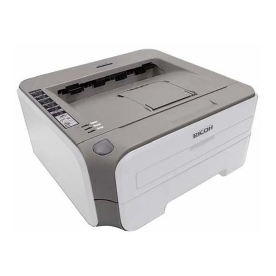
- Page 4 Appearance BL-P1 (M087/M088) This is the machine you will study in this training course. The two models are externally the same. The BL-P1b (M087) has NIC and USB2.0 interfaces but the BL-P1a (M088) does not. The BL-P1a (M088) will be marketed in China only. The BL-P1b (M087) will be marketed in the Americas, Europe, and Asia/Oceania (but not China).
- Page 5 External Components – Front 1. Face-down output tray support flap 2 7. Paper tray 2. Face-down output tray support flap 1 8. Front cover 3. Control panel 9. Power switch 4. Manual feed paper guide 10. Ventilation grid 5. Manual feed slot 11.
- Page 6 External Components – Rear 1. Back cover (back output tray) 4. 10/100BASE-TX port* 2. AC power connector 5. USB connector 3. Network status LEDs* *BL-P1b (M087) only No additional notes.
-
Page 7: Control Panel
Control Panel Toner LED The Toner LED indicates when the Toner is low or at the end of its life. Drum LED The Drum LED indicates when the Drum is nearing the end of its life. Error LED The Error LED indicates when the printer is in one of the following states: No paper / Paper jam / Cover... - Page 8 Market Positioning and Concept Main Objective Maintain and expand MIF in the low end market Target Users Business personal (1 to 4 users) Small office (5 to 29 users) Can double as a small office printer/copier Key sales points Small, stable, and convenient laser printer Low TCO* Low environmental impact (ECO friendly) Features...
-
Page 9: Reliability Targets
Reliability Targets Toner yield Starter toner: Approximately 1,000 sheets Toner: Approximately 2,600 sheets (Approximate toner yield calculations based on the ISO/IEC 19752 standard.) Drum yield: Approximately 12,000 sheets Expected product life: 5 years or 50K prints No additional notes. - Page 10 Model BL-P1 (M087/M088) Service Training 2. Specifications No additional notes.
-
Page 11: General Specifications
General Specifications Resolution: 300 dpi, 600 dpi, 2400 x 600 dpi Print speed: 22 ppm (A4), 23 ppm (8½" x 11") First copy time: Less than 10 seconds Paper tray capacity: 250 sheets By-pass tray capacity: 1 sheet Paper weight Cassette: 60 –... - Page 12 Model BL-P1 (M087/M088) Service Training 3. Installation No additional notes.
- Page 13 Overview Generally, the user installs this machine. However, in addition to your maintenance duties, you may also have to install the machine when you are in the field. The full installation procedure is in the Setting Up the Machine section of the Quick Setup Guide. Before you start installation: Check the accessories.
-
Page 14: Install The Machine
Install the Machine The following are the main steps to installation. Refer to the Quick Setup Guide (QSG) for details. Install the drum unit. Load paper in the paper tray. Connect the power cord. Do a test print. In addition to the above, the user may ask you to set up their computer for printing. - Page 15 Model BL-P1 (M087/M088) Service Training 4. Machine Overview No additional notes.
-
Page 16: Component Layout
Component Layout Main print engine components viewed in cross-section. (The name table is in the notes. Use Notes Page view.) Familiarize yourself with the main components. 1. Laser unit 15. Pressure roller 2. Supply roller 16. Heat roller 3. Development roller 17. -
Page 17: Overall Control
Overall Control Control System NVRAM Video/Engine External device Parallel ROM control (Only M087) The chart shows User interface Serial ROM Operation panel the overall control (Only M088) flow within the Operation panel machine. Feed System Imaging System Drive Laser Paper tray (DC motor) Fusing unit Drum unit... -
Page 18: Paper Path
Paper Path Upper eject Manual feed Rear eject Paper tray feed The red lines show the paths the paper takes through the machine. No additional notes. - Page 19 Model BL-P1 (M087/M088) Service Training 5. Service Maintenance (Maintenance Mode, Cleaning) No additional notes.
- Page 20 Entering Maintenance Modes Entering User Mode Basically used for service maintenance but it may be disclosed to users if necessary. To enter User Mode: 1. Turn off the power and confirm that Go Button the front cover is closed. 2. Turn on the power while pressing the Go button.
-
Page 21: User Maintenance Mode
User Maintenance Mode After entering User Mode, press the Go button from 1 to 8 times to select a maintenance function or mode as shown by the following table. Refer to the FSM for details about the individual functions or modes. Press Go Button Resulting Function/Mode Once... - Page 22 Service Maintenance Mode – 1 After entering Service Mode, press the SW supporter once to select service mode set 1 (table below). Confirm that the Toner, Drum, and Error LEDs light. Press the SW supporter from 1 to 7 times to select a maintenance function or mode as shown by the following table.
- Page 23 Service Maintenance Mode – 2 After entering Service Mode, press the SW supporter twice to select service mode set 2 (table below). Confirm that the Toner, Drum, and Error LEDs light. Press the SW supporter from 1 to 5 or 7 times to select a maintenance function or mode as shown by the following table.
-
Page 24: Resetting The Drum Counter
Resetting the Drum Counter When the drum unit is replaced, the drum counter must be reset. Refer to the FSM or the User's Guide for the procedure and for other details. Service Maintenance Other Service functions Resetting the Drum Counter User's Guide Routine Maintenance Drum... - Page 25 Initializing the Developer Bias A new toner cartridge is detected by the new toner sensor and developer bias is initialized automatically. If a previously installed toner cartridge (containing sufficient toner) is installed, you must force development bias initialization. Refer to the FSM for the procedure and for other details.
- Page 26 Cleaning This machine designed for user maintenance; so, it does not have a periodic maintenance schedule. As a preventive maintenance measure, you may need to clean machine components during service calls. Go to the machine and practice cleaning procedures. Pay particular attention to cleaning the drum. Refer to the User's Guide for the cleaning procedures.
- Page 27 Model BL-P1 (M087/M088) Service Training 6. Mechanical Operation No additional notes.
-
Page 28: Paper Lift
Paper Lift 1 Bottom plate Lift gear Bottom plate arm The bottom plate of the paper tray is pushed up by the main motor (not by springs). The pressure is kept constant to optimize paper-feeding performance irrespective of the quantity of paper remaining in the tray. After paper is inserted, the main motor drives the lift gear by way of several gears. - Page 29 Paper Lift 2 Roller holder Lift arm Hook B Clutch Hook A Clutch cam When paper reaches the feed position, the roller holder goes up. Then the lift arm goes down and hook B is released. The clutch cam released by hook B rotates to push down the rib of the hook A. Hook A releases the ratchet of the clutch and the bottom plate lift arm stops its push-up function.
-
Page 30: Paper Feed
Paper Feed The feed roller moves paper to the separation pad and separation roller. The separation roller Separation roller turns to feed paper to the separation roller. The separation pad strips off the top Trailing edge sheet. actuator Separation pad The trailing edge actuator is for misfeed detection. -
Page 31: Paper Registration
Paper Registration The registration front actuator detects the Registration leading edge of the Registration Transfer front actuator rear actuator paper. roller Registration rollers The leading edge of the paper then contacts the registration rollers, which are not turning at that time, and buckles slightly, correcting skew. - Page 32 Image Fusing and Paper Ejection Eject rollers Outer chute Eject actuator Fuser unit Heat roller Pressure roller Toner is fused to the paper by the heat roller and pressure roller of the fuser unit. Paper moves along the outer chute and is ejected face-down into the output tray by the eject rollers.
- Page 33 Manual Feed and Back Ejection Manual feed slot cover Back cover Registration Registration Eject actuator front actuator rear actuator When manual feeding, one sheet of paper is inserted through the manual feed slot. The registration front actuator detects the paper, and shortly after that the registration rollers start turning to feed the paper.
- Page 34 Model BL-P1 (M087/M088) Service Training 7. Print Processes No additional notes.
- Page 35 Print Processes 1 – Overview Exposure Development Transfer Charge Fusing Printing is done by the five processes shown above No additional notes.
- Page 36 Print Processes 2 – Charge Corona wire Positive ions Drum Grid Corona charges the surface of the drum to +850 V. Grid ensures an even charge distribution. Aluminum sleeve of the drum is grounded, providing a path for the charge to go to ground upon exposure to light. The level of ozone expelled from the machine is less than 3.0 mg/h and therefore is not harmful to the human body.
- Page 37 Print Processes 3 – Laser Exposure Laser diode Lens A latent image is formed on the positively charged drum by light from the Polygon mirror laser unit. Where light strikes, the Laser unit resistance of the OPC layer drops and the charge on the drum surface goes through the aluminum core to...
- Page 38 Print Processes 4 – Development Charging Laser exposure Drum Bias: 450 V to 300 V (Varies depending on use) Metering blade Drum Supply Toner Development roller roller Development roller Supply roller applies toner to the development roller. Metering blade controls the thickness of the layer of toner on the development roller.
- Page 39 Print Processes 5 – Image Transfer Development Supply Drum roller roller Toner cartridge Transfer roller Toner The negatively charged transfer roller attracts the toner from the drum to the paper. The negative bias applied in the transfer roller is adjusted according to types and sizes of paper so as to keep consistent image quality.
- Page 40 Print Processes 6 – Fusing Halogen lamp Thermistor Fusing unit Heat roller Pressure roller The image is fixed to the paper by heat and pressure as the paper passes through the fusing unit. A thermistor monitors the heat roller temperature and the halogen lamp turns on/off to maintain a constant heat roller temperature.
- Page 41 Model BL-P1 (M087/M088) Service Training 8. Toner Cartridge No additional notes.
- Page 42 New Toner Cartridge Detection New toner sensor When a new toner New toner actuator New toner cartridge is actuator installed, the rib on the reset gear rotates the new toner actuator and Reset gear Toner the new toner cartridge New toner switch turns on.
- Page 43 Development Bias Control <Actual Bias Control> <Toner Properties> Density and Density and Print density Voltage Voltage Print density Bias voltage Bias voltage Total Prints Total Prints Toner properties change over the course of usage. With constant bias, the print density would slowly increase. To maintain constant print density, the bias voltage is gradually decreased based on print count.
- Page 44 Model BL-P1 (M087/M088) Service Training 9. Replacement and Adjustment No additional notes.
-
Page 45: Before You Start
Before You Start Safety Precautions It is important to observe the all safety precautions during maintenance work. Refer to the list of safety precautions in the field service manual. » FSM Replacement and Adjustment Safety Precautions Additionally, pay attention to all notes and cautions related to specific procedures elsewhere in the FSM. -
Page 46: Removing And Replacing Parts
Removing and Replacing Parts Disassembly Flowchart Refer to the disassembly flowchart in the FSM. » FSM Replacement and Adjustment Disassembly Flow The disassembly flowchart shows what components must be removed and the order of removal in order to access target components. -
Page 47: Harness Routing
Harness Routing The "Harness Routing" section of the FSM shows the positioning of harnesses and wires in the machine. Refer to it when reassembling the machine. Replacement and Adjustment < Example Harness Routing Diagram > Harness Routing No additional notes. - Page 48 Adjustment after Parts Replacement Adjustments and settings changes are required after replacing the following parts. Main PCB Laser Unit Refer to the FSM for the details. Replacement and Adjustment Adjustments and Updating of Settings, Required After Parts Replacement No additional notes.
- Page 49 Model BL-P1 (M087/M088) Service Training 10. Troubleshooting No additional notes.
-
Page 50: Troubleshooting
Troubleshooting Practice: Troubleshooting Study the Troubleshooting sections of the FSM appendix and User's Guide. Simulate some of the error conditions on the machine. No additional notes. - Page 51 Model BL-P1 (M087/M088) Service Training 11. Technology for Environmental Conservation This section explains the technology used in this machine for environmental conservation, and the default settings of related functions.
- Page 52 Technology for Environmental Conservation **: New or modified function *: Has this function Blank: Does not have this function Environmental Description M087/M088 Technology/Feature 1. QSU - Reduction of warm-up time (Energy saving) 2. Hybrid QSU - Reduction of CO emissions 3.
- Page 53 Brief Descriptions of the Technologies 1. QSU (Quick Start-up) This technology reduces both the amount of energy consumed while in Standby mode (the Ready condition) is reduced, as well as the time it takes for the machine to warm up to the Ready condition. This is made possible through the utilization of dual fusing lamp heating, low fusing point toner, a pressure roller with a "sponge"...
- Page 54 Brief Descriptions of the Technologies 3. IH QSU This technology incorporates IH (Inductance Heating) technology into conventional QSU technology, which allows the benefits of reduced energy consumption and reduced warm-up time to be extended to color machines. 4. Paper-saving features 1) The duplex (double-sided) and Combine features reduce paper consumption.
- Page 55 Brief Descriptions of the Technologies 5. High-speed duplex output 1) Enables high-speed duplex printing through the utilization of the Duplex Interleaf and high- speed Inverter Transport features. 2) Enables quick printing of duplex jobs through the use of Duplex Scanning. 6.
- Page 56 Brief Descriptions of the Technologies 7. PxP (polymerized) toner "PxP toner" is a fine-particle, polyester resin based toner, manufactured using a Ricoh-original polymerization method instead of the conventional pulverization method. This allows the toner to fuse at a lower temperature, which reduces the impact on the environment and contributes to achieving even higher image quality than before.
- Page 57 1) Products sold in the EU conform to the RoHS Directive. 2) Products sold in China conform to China's version of the RoHS Directive. 3) In addition, Ricoh imposes strict internal standards for limiting the presence of harmful substances. No additional notes...
- Page 58 Brief Descriptions of the Technologies 10. Environmentally-friendly toner bottle A changeover from PS/PP/HDP to PET plastics allows approximately 40 percent by weight of the toner bottle to be recycled, and also reduces CO emissions that occur during the toner bottle manufacturing process. 11.
- Page 59 2. Energy Saving 2.1 Overview – 1 Power Consumption Warm-up Operation Mode Ready Mode Energy Saving Off/Sleep Mode Plug In Time Auto Off Timer Timer Starts After 99 min 0 – 99 min from last job Energy Saver Modes Description Sleep Mode Reduces power consumption.
- Page 60 2. Energy Saving 2.2 Overview – 2 (System Settings) Power Consumption Warm-up Operation Mode Ready Mode Off/Sleep Mode Plug In Time Auto Off Timer Timer Starts After 99 min 0 – 99 min from last job 1) Timer settings and recovery time (System settings => Timer setting) Mode Timer Default...
- Page 61 2. Energy Saving 2.2 Energy Saver Mode: Sleep Mode – 3 The machine recovers to the ready condition: If the operation switch is pressed » The operation panel lights. When warm-up is finished, the machine goes to the ready condition. »...
- Page 62 End of Course No additional notes.