Table of Contents
Advertisement
Advertisement
Table of Contents

Related Manuals for Ricoh Aficio SP 100


Summary of Contents for Ricoh Aficio SP 100
- Page 1 Model ME-P1/MF1 (M101/M102/M103) Service Training Draft started: 6 June, 2011 Released: 22 August, 2011 (Chinese only version) Update: 16 September, 2011 (Corrections applied) Update: 19 December, 2011 (International version released) Update: 27 February, 2012 (Minor corrections)
- Page 2 Course Contents 1. Product Outline 2. Specifications 3. Installation 4. Machine Overview 5. Service Maintenance 6. Mechanical Operation 7. Print Processes 8. AIO Cartridge 9. Replacement and Adjustment 10. Troubleshooting 11. Environmental Conservation - A note to the training supervisor - This course was written assuming the following requirements.
- Page 3 Model ME-P1/MF1 (M101/M102/M103) Service Training 1. Product Outline No additional notes.
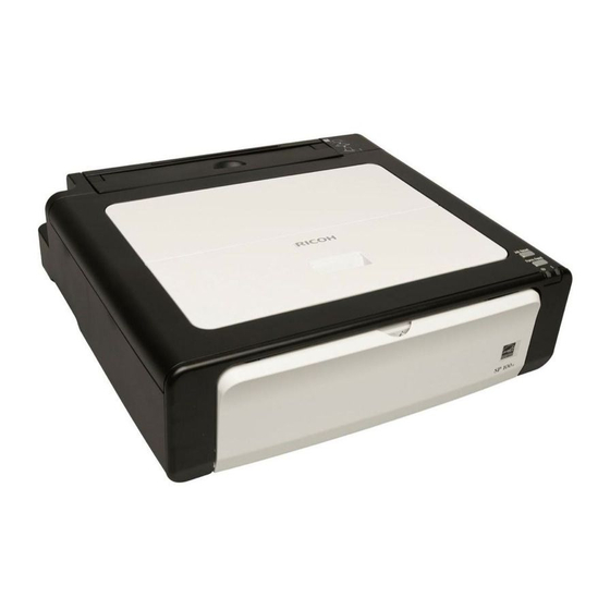
- Page 4 Appearance ME-P1 (M101) ME-MF1a (3in1) (M102) ME-MF1b (4in1) (M103) These are the machines you will study in this training course. The three models vary in appearance depending on functions. (See notes below.) Other non-visible differences will be covered later in the course. The M103 has copier, scanner, printer, and fax functions (= 4in1).
- Page 5 External Components – M101 (Printer) 1. Maintenance cover 7. Output tray extension 2. Input tray 8. Front cover 3. Power indicator 9. USB port 4. Resume key 10. Input tray cover 5. Cancel key 11. Power switch 6. Alert indicator See the Quick Start Guide for a list of components in the shipping carton.
- Page 6 External Components – M102 (3in1) 1. Control panel 6. Output tray extension 2. Exposure glass cover 7. Front cover 3. Input tray 8. Maintenance cover 4. Exposure glass 9. USB port 5. Input tray cover 10. Power switch See the Quick Start Guide for a list of components in the shipping carton. See the User's Guide for detailed external component descriptions.
- Page 7 External Components – M103 (4in1) 1. Control panel 9. Output tray 2. ADF cover 10. Maintenance cover 3. ADF input tray 11. Auto document feeder (ADF) 4. ADF extension tray 12. Original tray extension 5. Paper tray 13. USB port 6.
- Page 8 Operation Panel – M102 (3in1) Chinese Version 1. Display screen 6. Stop/Cancel key 2. Copy number key 7. Start key 3. Density indicator 8. Power indicator 4. Density key 9. Alert indicator 5. ID copy key See the User's Guide for detailed operation panel descriptions.
- Page 9 Operation Panel – M102 (3in1) NA Version 1. Display screen 6. Stop/Cancel key 2. Copy number key 7. Start key 3. Density indicator 8. Power indicator 4. Density key 9. Alert indicator 5. ID copy key See the User's Guide for detailed operation panel descriptions.
- Page 10 Operation Panel – M102 (3in1) EU Version The EU version uses symbols rather than text labels. See the previous slide for descriptions. See the User's Guide for detailed operation panel descriptions.
- Page 11 Operation Panel – M103 (4in1) Chinese Version 1. Copy/Fax key 7. ID copy/On hook key 2. Speed dial key 8. Power indicator 3. Menu key 9. Display screen 4. OK key 10. Alert indicator 5. Cancel/Stop key 11. Scroll keys 6.
- Page 12 Operation Panel – M103 (4in1) NA Version 1. Copy/Fax key 7. ID copy/On hook key 2. Speed dial key 8. Power indicator 3. Menu key 9. Display screen 4. OK key 10. Alert indicator 5. Cancel/Stop key 11. Scroll keys 6.
- Page 13 Operation Panel – M103 (4in1) EU Version The EU version uses symbols rather than text labels. See the previous slide for descriptions. See the User's Guide for detailed operation panel descriptions.
- Page 14 Market Positioning and Concepts Main Objective Maintain and expand MIF in the low end market Target Users Business personal and small office Can double as a small office printer/copier/fax Technical Enhancements (compared to some competitors/predecessors) Compact » Small footprint » Lowest height Genuine refill toner Fast first print Height of M101...
-
Page 15: Reliability Targets
Reliability Targets AIO yield (Starter): Approximately 500 sheets AIO yield (Supply): China model -- Approximately 2,000 sheets. Others -- TBA When printing A4 or 8½" x 11" paper in accordance with ISO/IEC 19752. Expected product life: 5 years or 50,000 prints (whichever comes first) No additional notes. - Page 16 Names, Codes, and Distribution Destination Brand Model name Product name Product code Type ME-P1 Aficio SP 100 M101-17 North America Ricoh ME-MF1a Aficio SP 100SU M102-17 ME-MF1b Aficio SP 100SF M103-17 ID Chip Model ME-P1 Aficio SP 100 M101-27 EU/Asia-Pacific...
- Page 17 Model ME-P1/MF1 (M101/M102/M103) Service Training 2. Specifications No additional notes.
-
Page 18: General Specifications
General Specifications Resolution: Output (print/copy): 600 x 600 dpi Scan from exposure glass: 600 x 600 dpi, 600 x 300 dpi Scan from ADF: 600 x 300 dpi Print/Copy speed: 13 ppm (A4/LT SEF) Warm up time: Less than 25 s at 23°C First print time: Less than 6.4 s from the start of paper feed until paper exits. - Page 19 Model ME-P1/MF1 (M101/M102/M103) Service Training 3. Installation No additional notes.
- Page 20 Overview Generally, the user installs this machine. However, in addition to your maintenance duties, you may also have to install the machine when you are in the field. The full installation procedure is in the Quick Installation Guide. Before you start installation: Check the accessories.
-
Page 21: Install The Machine
Install the Machine The following are the main steps to installation. Refer to the Quick Installation Guide (QIG) for details. Unpack the machine. Take out, shake, and reinstall the AIO (print cartridge). Connect the power cord and USB cord. Install the printer software in the computer. Load paper in the paper tray and open the output tray. - Page 22 Model ME-P1/MF1 (M101/M102/M103) Service Training 4. Machine Overview No additional notes.
-
Page 23: Component Layout
Component Layout Development Charge Fusing unit roller roller Laser unit Paper tray Drum Exit rollers Pressure roller Registration sensor Pick-up roller Paper feed rollers Exit sensor Hot roller Transfer roller Familiarize yourself with the main print engine components shown above. No additional notes. - Page 24 ADF and FB Scanner Component Layout Separation Pick-up roller Input tray roller Feed sensor Output tray Transport rollers ADF exposure glass Scanner (CIS) Scanner motor Pressure plate Set sensor Exit rollers Scanner exposure glass Familiarize yourself with the main ADF and flatbed scanner components shown above.
- Page 25 Electrical Component Layout – Main Unit Main board Main switch Thermostat Safety switch Pick-up roller solenoid Main motor Thermistor Power supply unit (PSU) Operation panel (M101) High voltage power supply (HVPS) Registration Fusing lamp Exit switch sensor Familiarize yourself with the main electrical components shown above.
- Page 26 Electrical Component Layout – M103 Main board Fax board Main motor ADF set sensor Scanner (CIS) ADF motor Speaker Scanner motor Operation panel ADF feed sensor Familiarize yourself with the M103 electrical components shown above. No additional notes...
- Page 27 Main Unit Drive The main motor (1) and a gear train (2) drive the pickup roller (3), the feed rollers (4), the drum (5, inside the AIO), the hot roller (6), the pressure roller (7), and the exit rollers (8). The pickup roller solenoid (9) engages and disengages the rotation of the pickup roller during paper feed.
- Page 28 Right Side Cover Off (M103) Main motor Main board Speaker The fax board is behind the main board. No additional notes.
- Page 29 Left Side Cover Off (M103) Main switch High voltage power pack No additional notes.
- Page 30 Control Structure – M101 High Power voltage The illustration supply board unit shows the Polygon motor overall control Feed ID chip solenoid structure of the M101 (printer). Main Board Debug Operation panel Debug I/F Debug I/F Main Fu Therm / Regist I/L SW motor...
- Page 31 Control Structure – M102 High Power voltage The illustration supply board Operation unit shows the Polygon panel motor overall control Feed ID chip solenoid structure of the M102 (3in1). Main Board Debug Debug I/F Debug I/F Main Fu Therm / Regist I/L SW Motor...
- Page 32 Control Structure – M103 High Power voltage The illustration supply board unit shows the Polygon motor overall control Feed ID chip solenoid structure of the M103 (4in1). Operation panel Main Board Debug Debug I/F Debug I/F Main Regist Fu Therm / I/L SW Motor Motor...
- Page 33 Main Unit Paper Path The red line shows the path that paper takes through the machine. The registration sensor sets registration timing. (= Laser on timing)
-
Page 34: Adf Paper Path
ADF Paper Path The red line shows the path that documents take through the ADF. No additional notes. - Page 35 Model ME-P1/MF1 (M101/M102/M103) Service Training 5. Maintenance (Maintenance, Service mode, Cleaning) No additional notes.
-
Page 36: Maintenance Procedures
Maintenance Procedures This machine designed for user maintenance; so, it does not have a periodic maintenance schedule. Refer to the maintenance information in the User Guide. Operating Instructions: User Guide Maintaining the Machine Also see the "Using the Service Mode" slide. No additional notes. -
Page 37: Configuring The Machine
Configuring the Machine The M103 can be configured/set-up from the control panel. User Guide Configuring the Machine Using the Control Panel All three models can be configured/set-up using the Smart Organizing Monitor. User Guide Configuring the Machine Using the Smart Organizing Monitor Refer to "User Maintenance Mode"... -
Page 38: Using The Service Mode
Using the Service Mode The method for entering the service mode depends on the function item and the model. Refer to the table below. The Service Mode PC utility is accessed from within the Smart Organizing Monitor. For full details see the FSM. Troubleshooting Utilities Smart Organizing Monitor... - Page 39 Opening the Service Mode Image area "About" button To open the Service Mode: Step 1: Click "About". Step 2: Press Ctrl+Shift and double click the right mouse button in the image area of the Smart Organizing Monitor. (Orange outlined area above.) No additional notes.
- Page 40 Cleaning This machine designed for user maintenance; so, it does not have a periodic maintenance schedule. As a preventive maintenance measure, you may need to clean machine components during service calls. Go to the machine and practice cleaning procedures. Refer to the User Guide for the cleaning procedures.
- Page 41 Model ME-P1/MF1 (M101/M102/M103) Service Training 6. Mechanical Operation No additional notes.
-
Page 42: Paper Feed
Paper Feed The pick-up roller solenoid Pick-up roller Paper turns on, releasing the pick-up roller clutch. The pick-up roller makes a single rotation. The pick-up roller moves a sheet of paper to the paper feed rollers. The separation pad allows only the top sheet of paper to pass. - Page 43 Registration Laser unit Registration timing starts when the leading edge of the paper activates the registration sensor. At 0.142 second after the registration sensor is activated, the control program starts the laser and writes the image on the drum. Drum Registration sensor Paper feed rollers Transfer roller...
-
Page 44: Image Transfer
Image Transfer The positively Drum (Negatively charged transfer charged roller attracts the toner image) negatively charged toner from the drum to the paper. Paper Transfer roller (Strong positive charge) No additional notes. -
Page 45: Image Fusing
Image Fusing 1. Hot roller 2. Fusing unit casing (upper) 3. Thermostat 4. Thermistor 5. Fusing lamp 6. Fusing unit casing (lower) 7. Pressure roller 8. Exit sensor actuator 9. Lower exit rollers 10. Upper exit rollers 11. Stripper pawls Toner is fused to the paper by the hot roller and pressure roller. - Page 46 Main Parts/Function of the Fusing Unit 1. Hot roller 2. Pressure roller 3. Thermistor 4. Thermostat 5. Fusing lamp Five basic devices comprise the fusing unit: The hot roller [1] applies heat to the toner and paper to fuse the toner on the surface of the paper.
-
Page 47: Fusing Temperature Control
Fusing Temperature Control A : Stop (machine idle) B : Start up C : Ready (Standby) D : Printing (paper feeding) C : Ready (Standby) E : Energy Save Mode 1 (Default: Machine idle 30 s) F : Energy Save Mode 2 (Default: Machine idle for 60 s) G : Recover from energy save mode C : Ready (Standby) After a cold start at "A"... -
Page 48: Paper Output
Paper Output Exit rollers 1. Output tray 2. Output tray extensions Paper moves through the exit rollers to the output tray. The output tray folds down away from the front of the machine. The extensions fold out and provide extended paper support. The output tray and extensions are fragile. -
Page 49: Document Scanning
Document Scanning CIS is stationary CIS moves during ADF scanning. during flatbed scanning This machine uses a dual scanning system: ADF scanning and flat-bed scanning. In ADF scanning, the document moves past the stationary CIS unit. (M103 only) In flat-bed scanning, the CIS moves under a stationary document. -
Page 50: Flatbed Scanner
Flatbed Scanner 1. CIS 2. Scanner (CIS cradle) 3. Timing belt 4. Scanner motor The M102 and M103 have the flatbed scanner. The CIS (1) and flatbed scanner motor (2) are the only two electrical components in the flatbed scanner. No additional notes. - Page 51 Flatbed vs ADF Scanning Flatbed scanning ADF scanning For flatbed scanning the original is placed at the left-rear. During ADF scanning the original passes over the center of the CIS. Flatbed scanning can be done with the M102 and M103. ADF scanning is only possible with the M103.
- Page 52 Flatbed Hinge Mechanism (M102, M103) One spring-loaded hinge is used to raise and lower the top of the machine. The hinge is mounted on the top of the left cover and connected to the bottom of the flatbed unit. The hinge locks and holds when the top of the machine is raised.
- Page 53 Model ME-P1/MF1 (M101/M102/M103) Service Training 7. Print Processes No additional notes.
- Page 54 Print Processes The following cycle is repeated for each sheet of paper. Exposure Development Transfer Charge The charge roller [1] applies a high negative charge (about -1000 V) to the photoconductive surface of the drum [2]. The laser beam [3] creates a latent image on the drum.
- Page 55 Model ME-P1/MF1 (M101/M102/M103) Service Training 8. AIO Cartridge No additional notes.
-
Page 56: Aio Cartridge
AIO Cartridge 1. Waste toner tank 2. Development roller 3. Doctor blade 4. Toner hopper 5. ID chip* 6. Agitator 7. Toner paddle 8. Toner supply roller 9. Transfer roller 10. Drum 11. Charge roller 12. Cleaning blade The main components of the AIO (all in one) cartridge are shown above. -
Page 57: Toner End Detection
Toner End Detection Machines without ID chip in AIO These machines have no system to alert the operator when the toner supply of the AIO is at near end or toner end. The operator simply replaces the AIO when printed sheets become faint or blurred. - Page 58 Model ME-P1/MF1 (M101/M102/M103) Service Training 9. Replacement and Adjustment No additional notes.
-
Page 59: Before You Start
Before You Start Safety Precautions It is important to observe the all safety precautions during maintenance work. Refer to the safety precautions in the field service manual. » FSM Safety, Symbols, Trademarks » FSM Replacement and Adjustment Before You Begin Additionally, pay attention to all notes and cautions related to specific procedures elsewhere in the FSM. -
Page 60: Removing And Replacing Parts
Removing and Replacing Parts Disassembly Practice Referencing the FSM, go to the machine and practice removing and reinstalling parts. Observe all notes and cautions. No additional notes. -
Page 61: Refilling The Aio
Refilling the AIO The AIO is designed to be easy to refill. (Easily removable caps allow easy toner tank refill and waste toner removal. No screws to remove.) Drum life is the limiting factor. The AIO can be refilled 2 or 3 times (depends on use). - Page 62 Adjustment after Parts Replacement Adjustments and settings changes are required after replacing the following parts. Refer to the FSM for the details. Main board Replacement and Adjustment After Replacing the Main Board Laser unit Replacement and Adjustment Laser Unit (See "After Replacement" at the end of the removal procedure.) No additional notes.
- Page 63 Adjustment after Servicing Adjustments are required after performing the following service procedures. Refer to the FSM for the details. After a fatal fusing error you must execute [Fuser SC Reset] to recover machine operation. » FSM Troubleshooting Fusing Related SC Codes »...
- Page 64 Model ME-P1/MF1 (M101/M102/M103) Service Training 10. Troubleshooting No additional notes.
-
Page 65: Error Messages And Codes
Error Messages & Codes Error notification depends on the model. The three models have different operation panels with different display capability. Error status can be checked on all three models using the Smart Organizing Monitor. Refer to the Error Notification Matrix below. The notes section has additional information. -
Page 66: Troubleshooting
Troubleshooting Image Problems at Regular Intervals Image problems can occur at regular intervals due to problems with rollers in the machine and inside the AIO. See the table listing roller circumferences. Troubleshooting Image Problems Overview Using Test Pages and Print Patterns Use test pages and print patterns to check for image problems. - Page 67 Model ME-P1/MF1 (M101/M102/M103) Service Training 11. Technology for Environmental Conservation This section explains the technology used in this machine for environmental conservation, and the default settings of related functions.
- Page 68 Technology for Environmental Conservation **: New or modified function *: Has this function Blank: Does not have this function Environmental Technology/Feature Description M101/ M102/M103 1. QSU - Reduction of warm-up time (Energy saving) 2. Hybrid QSU - Reduction of CO emissions 3.
- Page 69 Brief Descriptions of the Technologies 1. QSU (Quick Start-up) This technology reduces both the amount of energy consumed while in Standby mode (the Ready condition) is reduced, as well as the time it takes for the machine to warm up to the Ready condition. This is made possible through the utilization of dual fusing lamp heating, low fusing point toner, a pressure roller with a "sponge"...
- Page 70 Brief Descriptions of the Technologies 3. IH QSU This technology incorporates IH (Inductance Heating) technology into conventional QSU technology, which allows the benefits of reduced energy consumption and reduced warm-up time to be extended to color machines. 4. Paper-saving features 1) The duplex (double-sided) and Combine features reduce paper consumption.
- Page 71 Brief Descriptions of the Technologies 5. High-speed duplex output 1) Enables high-speed duplex printing through the utilization of the Duplex Interleaf and high- speed Inverter Transport features. 2) Enables quick printing of duplex jobs through the use of Duplex Scanning. 6.
- Page 72 Brief Descriptions of the Technologies 7. PxP (polymerized) toner "PxP toner" is a fine-particle, polyester resin based toner, manufactured using a Ricoh-original polymerization method instead of the conventional pulverization method. This allows the toner to fuse at a lower temperature, which reduces the impact on the environment and contributes to achieving even higher image quality than before.
- Page 73 1) Products sold in the EU conform to the RoHS Directive. 2) Products sold in China conform to China's version of the RoHS Directive. 3) In addition, Ricoh imposes strict internal standards for limiting the presence of harmful substances. No additional notes...
- Page 74 Brief Descriptions of the Technologies 10. Environmentally-friendly toner bottle A changeover from PS/PP/HDP to PET plastics allows approximately 40 percent by weight of the toner bottle to be recycled, and also reduces CO emissions that occur during the toner bottle manufacturing process. 11.
-
Page 75: Energy Saving
Energy Saving Overview Power Consumption Warm-up Operation Mode Ready Mode Energy Saving Energy Saver Mode Plug In Time Time Auto Off Timer Timer Starts 1 – 30 min Timer settings and recovery time (Smart Organizing Monitor User Tool Printer Configuration) Mode Timer Default... - Page 76 End of Course No additional notes.