Juniper SRX320 Hardware Manual
Hide thumbs
Also See for SRX320:
- Hardware manual (113 pages) ,
- Quick start manual (14 pages) ,
- Setup (8 pages)

Related Manuals for Juniper SRX320


Summary of Contents for Juniper SRX320
- Page 1 SRX320 Services Gateway Hardware Guide Modified: 2016-09-09 Copyright © 2016, Juniper Networks, Inc.
- Page 2 END USER LICENSE AGREEMENT The Juniper Networks product that is the subject of this technical documentation consists of (or is intended for use with) Juniper Networks software. Use of such software is subject to the terms and conditions of the End User License Agreement (“EULA”) posted at http://www.juniper.net/support/eula.html.
-
Page 3: Table Of Contents
SRX320 Services Gateway Description ........3... - Page 4 Required Tools and Parts for Unpacking the SRX320 Services Gateway ..45 Unpacking the SRX320 Services Gateway ....... 45 Verifying Parts Received with the SRX320 Services Gateway .
- Page 5 About the Guided Setup Mode ........76 Accessing the CLI on the SRX320 Services Gateway ..... . . 77 Connecting to the SRX320 Services Gateway from the CLI Remotely .
- Page 6 Agency Approvals and Regulatory Compliance Information ... . 131 SRX320 Services Gateway Agency Approvals ......131 SRX320 Services Gateway Acoustic Noise Compliance Statements .
- Page 7 Chassis Description ..........5 Figure 1: SRX320 Services Gateway Front Panel ......6 Figure 2: SRX320 Services Gateway Front Panel LEDs .
- Page 8 SRX320 Services Gateway Hardware Guide viii Copyright © 2016, Juniper Networks, Inc.
- Page 9 Chapter 12 Unpacking the SRX320 Services Gateway ......45 Table 14: Parts List for a Fully Configured SRX320 Services Gateway ..46 Table 15: Accessory/Upgrade Parts List for the SRX320 Services Gateway .
- Page 10 Actions ............88 Table 19: SRX320 Services Gateway Power LED Status ....89...
-
Page 11: About The Documentation
® To obtain the most current version of all Juniper Networks technical documentation, see the product documentation page on the Juniper Networks website at http://www.juniper.net/techpubs/ If the information in the latest release notes differs from the information in the documentation, follow the product Release Notes. -
Page 12: Table 1: Notice Icons
SRX320 Services Gateway Hardware Guide Table 1: Notice Icons Icon Meaning Description Informational note Indicates important features or instructions. Caution Indicates a situation that might result in loss of data or hardware damage. Warning Alerts you to the risk of personal injury or death. -
Page 13: Documentation Feedback
We encourage you to provide feedback, comments, and suggestions so that we can improve the documentation. You can provide feedback by using either of the following methods: Online feedback rating system—On any page of the Juniper Networks TechLibrary site , simply click the stars to rate the content, http://www.juniper.net/techpubs/index.html and use the pop-up form to provide us with information about your experience. -
Page 14: Requesting Technical Support
7 days a week, 365 days a year. Self-Help Online Tools and Resources For quick and easy problem resolution, Juniper Networks has designed an online self-service portal called the Customer Support Center (CSC) that provides you with the following features: Find CSC offerings: http://www.juniper.net/customers/support/... - Page 15 About the Documentation For international or direct-dial options in countries without toll-free numbers, see http://www.juniper.net/support/requesting-support.html Copyright © 2016, Juniper Networks, Inc.
- Page 16 SRX320 Services Gateway Hardware Guide Copyright © 2016, Juniper Networks, Inc.
-
Page 17: Overview
PART 1 Overview System Overview on page 3 Chassis Description on page 5 Interface Module Descriptions on page 11 Cooling System Description on page 13 Power System Description on page 15 Copyright © 2016, Juniper Networks, Inc. - Page 18 SRX320 Services Gateway Hardware Guide Copyright © 2016, Juniper Networks, Inc.
-
Page 19: System Overview
With a desktop form-factor chassis, the SRX320 Services Gateway has six 1 G Ethernet ports, two 1 G SFP ports, 4 GB of DRAM memory, 8 GB of flash memory, and two Mini-Physical Interface Module (Mini-PIM) slots. -
Page 20: Srx320 Services Gateway Cli And J-Web Access
SRX320 Services Gateway Hardware Guide SRX320 Services Gateway CLI and J-Web Access The SRX320 Services Gateway runs the Junos operating system (Junos OS). You can use two user interfaces to monitor, configure, troubleshoot, and manage the services gateway: J-Web interface—A Web-based graphical interface that allows you to operate the services gateway without commands. -
Page 21: Chassis Description
Understanding the SRX320 Services Gateway Back Panel on page 8 SRX320 Services Gateway Chassis Overview The SRX320 Services Gateway chassis measures 1.73 in. high, 11.81 in. wide, and 7.52 in. deep. The PoE model weighs 3.4 lb. and the non-PoE model weighs 3.28 lb. -
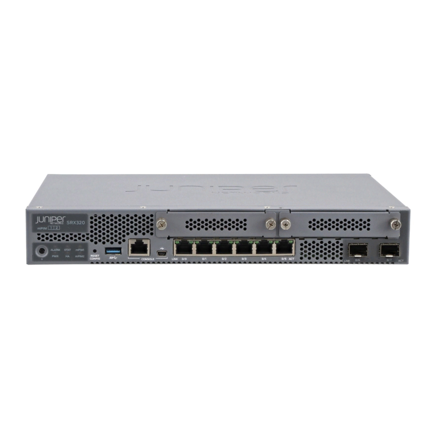
Page 22: Figure 1: Srx320 Services Gateway Front Panel
SRX320 Services Gateway Hardware Guide Figure 1: SRX320 Services Gateway Front Panel Table 3 on page 6 provides details about the front panel components. Table 3: SRX320 Services Gateway Front Panel Components Number Component Description Reset Config button Returns the services gateway to the rescue configuration or the factory-default configuration. -
Page 23: Figure 2: Srx320 Services Gateway Front Panel Leds
Chapter 2: Chassis Description Table 3: SRX320 Services Gateway Front Panel Components (continued) Number Component Description 1 G Ethernet ports Six Gigabit Ethernet LAN ports (0/0 to 0/5) The Gigabit Ethernet ports have the following characteristics: Use an RJ-45 connector... -
Page 24: Understanding The Srx320 Services Gateway Back Panel
Related SRX320 Services Gateway Chassis Overview on page 5 Documentation Understanding the SRX320 Services Gateway Back Panel on page 8 Understanding the SRX320 Services Gateway Back Panel Figure 3 on page 8 shows the back panel of the SRX320 Services Gateway and Table 5 on page 9 lists the components on the back panel. -
Page 25: Table 5: Srx320 Services Gateway Back Panel Components
(optional). NOTE: We recommend connecting the services gateway to ground if required. Related SRX320 Services Gateway Chassis Overview on page 5 Documentation Understanding the SRX320 Services Gateway Front Panel on page 5 Copyright © 2016, Juniper Networks, Inc. - Page 26 SRX320 Services Gateway Hardware Guide Copyright © 2016, Juniper Networks, Inc.
-
Page 27: Interface Module Descriptions
CAUTION: The Mini-PIMs are not hot-swappable. You must power off the services gateway before removing or installing Mini-PIMs. The following Mini-PIMs are supported on the SRX320 Services Gateway: 1-Port Serial Mini-Physical Interface Module (SRX-MP-1SERIAL-R) 1-Port T1/E1 Mini-Physical Interface Module (SRX-MP-1T1E1-R) - Page 28 SRX320 Services Gateway Hardware Guide Copyright © 2016, Juniper Networks, Inc.
-
Page 29: Cooling System Description
Understanding the SRX320 Services Gateway Cooling System on page 13 Understanding the SRX320 Services Gateway Cooling System The cooling system for the SRX320 Services Gateway includes two fixed fans. The fans draw air through vents on the front of the chassis and exhaust the air through the back of the chassis. - Page 30 SRX320 Services Gateway Hardware Guide Copyright © 2016, Juniper Networks, Inc.
-
Page 31: Power System Description
Understanding the SRX320 Services Gateway Power Supply on page 15 Understanding the SRX320 Services Gateway Power Supply The power supply for the SRX320 Services Gateway is external. You must use the following power supply adapters provided by Juniper Networks to provide power to the services gateway. - Page 32 SRX320 Services Gateway Hardware Guide Copyright © 2016, Juniper Networks, Inc.
-
Page 33: Site Planning And Specifications
Site Planning and Specifications Planning and Preparing the Site on page 19 Rack Requirements on page 25 Cabinet Requirements on page 31 Power Requirements and Specifications on page 33 Cable Specifications and Pinouts on page 37 Copyright © 2016, Juniper Networks, Inc. - Page 34 SRX320 Services Gateway Hardware Guide Copyright © 2016, Juniper Networks, Inc.
-
Page 35: Planning And Preparing The Site
SRX320 Services Gateway Environmental Specifications on page 19 Site Preparation Checklist for the SRX320 Services Gateway on page 20 General Site Installation Guidelines for the SRX320 Services Gateway on page 22 SRX320 Services Gateway Physical Specifications Table 6 on page 19 lists the physical specifications for the services gateway. -
Page 36: Site Preparation Checklist For The Srx320 Services Gateway
SRX320 Services Gateway Hardware Guide Table 7: Environmental Specifications for the SRX320 Services Gateway (continued) Description Value Relative humidity 5% to 95%, noncondensing Temperature Operational temperature—32° F (0° C) to 104° F (40° C) Nonoperational temperature—4° F (-20° C) to 158° F (70° C) - Page 37 Chapter 6: Planning and Preparing the Site Table 8: Site Preparation Checklist for SRX320 Services Gateway Installation (continued) Additional Item or Task Information Performed By Date Notes Measure the distance “SRX320 between the external Services power sources and Gateway the device installation Electrical Wiring site.
-
Page 38: General Site Installation Guidelines For The Srx320 Services Gateway
Plan the cable routing and management. Related General Site Installation Guidelines for the SRX320 Services Gateway on page 22 Documentation General Site Installation Guidelines for the SRX320 Services Gateway The following precautions help you plan an acceptable operating environment for your... - Page 39 Ensure that a blank Mini-PIM panel is installed in the empty slot to prevent any interruption or reduction in the flow of air across internal components. Related Site Preparation Checklist for the SRX320 Services Gateway on page 20 Documentation Copyright © 2016, Juniper Networks, Inc.
- Page 40 SRX320 Services Gateway Hardware Guide Copyright © 2016, Juniper Networks, Inc.
-
Page 41: Rack Requirements
SRX320 Services Gateway Rack-Mounting Requirements and Warnings on page 25 SRX320 Services Gateway Rack Size and Strength Requirements on page 29 SRX320 Services Gateway Spacing of Mounting Brackets and Flange Holes on page 29 SRX320 Services Gateway Clearance Requirements for Airflow and Hardware... - Page 42 Les directives ci-dessous sont destinées à assurer la protection du personnel: Le rack sur lequel est monté le Juniper Networks services gateway doit être fixé à la structure du bâtiment. Si cette unité constitue la seule unité montée en casier, elle doit être placée dans le bas.
- Page 43 Le seguenti direttive vengono fornite per garantire la sicurezza personale: Il Juniper Networks services gateway deve essere installato in un telaio, il quale deve essere fissato alla struttura dell'edificio. Questa unità deve venire montata sul fondo del supporto, se si tratta dell'unica unità...
- Page 44 Om ställningen är försedd med stabiliseringsdon skall dessa monteras fast innan enheten installeras eller underhålls på ställningen. Related SRX320 Services Gateway Rack Size and Strength Requirements on page 29 Documentation Copyright © 2016, Juniper Networks, Inc.
-
Page 45: Srx320 Services Gateway Rack Size And Strength Requirements
Chapter 7: Rack Requirements SRX320 Services Gateway Spacing of Mounting Brackets and Flange Holes on page 29 SRX320 Services Gateway Clearance Requirements for Airflow and Hardware Maintenance on page 30 SRX320 Services Gateway Rack Size and Strength Requirements When installing the services gateway in a rack, you must ensure that the rack complies with a 1U (19 in. -
Page 46: Srx320 Services Gateway Clearance Requirements For Airflow And Hardware
SRX320 Services Gateway Clearance Requirements for Airflow and Hardware Maintenance When planning the installation site for the SRX320 Services Gateway, you need to allow sufficient clearance around the device. Consider the following: For the operating temperature of the services gateway to be optimal, the airflow around the chassis must be unrestricted. -
Page 47: Cabinet Requirements
SRX320 Services Gateway Cabinet Airflow Requirements on page 31 SRX320 Services Gateway Cabinet Size and Clearance Requirements You can install the SRX320 Services Gateway in a 19 in. (48.7 cm) cabinet as defined in Cabinets, Racks, Panels, and Associated Equipment (document number EIA-310-D) published by the Electronic Industries Alliance ( http://www.ecaus.org/eia/site/index.html... - Page 48 Route and dress all cables to minimize the blockage of airflow to and from the chassis. Related SRX320 Services Gateway Cabinet Size and Clearance Requirements on page 31 Documentation Copyright © 2016, Juniper Networks, Inc.
-
Page 49: Power Requirements And Specifications
CHAPTER 9 Power Requirements and Specifications SRX320 Services Gateway Electrical Wiring Guidelines on page 33 SRX320 Services Gateway Power Specifications and Requirements on page 34 SRX320 Services Gateway Electrical Wiring Guidelines Table 9 on page 33 describes the factors you must consider while planning the electrical wiring for the services gateway at your site. -
Page 50: Srx320 Services Gateway Power Specifications And Requirements
SRX320 Services Gateway Hardware Guide Table 9: Site Electrical Wiring Guidelines for the SRX320 Services Gateway (continued) Site Wiring Factor Guideline Electromagnetic Provide a properly grounded and shielded environment and use Compatibility (EMC) electrical surge-suppression devices. Strong sources of electromagnetic interference (EMI) can cause... -
Page 51: Power Requirements And Specifications
Chapter 9: Power Requirements and Specifications Related SRX320 Services Gateway Electrical Wiring Guidelines on page 33 Documentation Understanding the SRX320 Services Gateway Power Supply on page 15 Copyright © 2016, Juniper Networks, Inc. - Page 52 SRX320 Services Gateway Hardware Guide Copyright © 2016, Juniper Networks, Inc.
-
Page 53: Cable Specifications And Pinouts
CHAPTER 10 Cable Specifications and Pinouts RJ-45 Connector Pinouts for the SRX320 Services Gateway Ethernet Port on page 37 RJ-45 Connector Pinouts for the SRX320 Services Gateway Console Port on page 37 Mini-USB Connector Pinouts for the SRX320 Services Gateway Console Port on page 38... -
Page 54: Mini-Usb Connector Pinouts For The Srx320 Services Gateway Console Port
Documentation Mini-USB Connector Pinouts for the SRX320 Services Gateway Console Port The SRX320 Services Gateway has two console ports: an RJ-45 Ethernet port and a mini-USB Type-B port. If your management device (laptop or PC) does not have a DB-9... -
Page 55: Cable Specifications And Pinouts
Black Ground Related RJ-45 Connector Pinouts for the SRX320 Services Gateway Ethernet Port on page 37 Documentation RJ-45 Connector Pinouts for the SRX320 Services Gateway Console Port on page 37 Copyright © 2016, Juniper Networks, Inc. - Page 56 SRX320 Services Gateway Hardware Guide Copyright © 2016, Juniper Networks, Inc.
-
Page 57: Initial Installation And Configuration
Installing the SRX320 Services Gateway on page 53 Connecting the SRX320 Services Gateway to Ground on page 61 Connecting the SRX320 Services Gateway to External Devices on page 65 Providing Power to the SRX320 Services Gateway on page 67 Performing the Initial Configuration on page 71... - Page 58 SRX320 Services Gateway Hardware Guide Copyright © 2016, Juniper Networks, Inc.
-
Page 59: Installation Overview
CHAPTER 11 Installation Overview SRX320 Services Gateway Installation Overview on page 43 Required Tools and Parts for Installing the SRX320 Services Gateway on page 44 SRX320 Services Gateway Autoinstallation Overview on page 44 SRX320 Services Gateway Installation Overview After you have prepared the site for installation and unpacked the SRX320 Services Gateway, you are ready to install the device. -
Page 60: Required Tools And Parts For Installing The Srx320 Services Gateway
SRX320 Services Gateway Hardware Guide SRX320 Services Gateway Autoinstallation Overview on page 44 Required Tools and Parts for Installing the SRX320 Services Gateway To install the services gateway, you need the following tools and parts: Phillips (+) screwdriver, number 2... -
Page 61: Unpacking The Srx320 Services Gateway
Verifying Parts Received with the SRX320 Services Gateway on page 46 Unpacking the SRX320 Services Gateway The SRX320 Services Gateway is shipped in a cardboard carton and secured with foam packing material. The carton also contains an accessory box and quick-start instructions. -
Page 62: Verifying Parts Received With The Srx320 Services Gateway
SRX320 Services Gateway chassis with six Gigabit Ethernet LAN ports, two 1 G SFP ports, and two Mini-PIM slots. PoE model SRX320 Services Gateway chassis with six PoE ports, two 1 G SFP ports, and two Mini-PIM slots. CAT5E cable... - Page 63 Table 15: Accessory/Upgrade Parts List for the SRX320 Services Gateway (continued) Part Quantity Safety Guide Related Required Tools and Parts for Unpacking the SRX320 Services Gateway on page 45 Documentation Unpacking the SRX320 Services Gateway on page 45 Copyright © 2016, Juniper Networks, Inc.
- Page 64 SRX320 Services Gateway Hardware Guide Copyright © 2016, Juniper Networks, Inc.
-
Page 65: Installing The Rack Mounting Hardware
Preparing the SRX320 Services Gateway for Desk-Mount Installation on page 50 Connecting the SRX320 Services Gateway to the Building Structure on page 51 Preparing the SRX320 Services Gateway for Rack-Mount Installation You can mount an SRX320 Services Gateway in four-post (telco) racks, enclosed cabinets, and open-frame racks. NOTE: The SRX320 Services Gateway cannot be center-mounted in racks. -
Page 66: Preparing The Srx320 Services Gateway For Wall-Mount Installation
Installing the SRX320 Services Gateway in a Rack on page 53 Preparing the SRX320 Services Gateway for Wall-Mount Installation You can mount an SRX320 Services Gateway on a wall. The four rubber feet attached to the chassis provide stability. Before mounting the SRX320 Services Gateway on a wall: Verify that the installation site meets the requirements described in “Site Preparation... -
Page 67: Connecting The Srx320 Services Gateway To The Building Structure
If your geographical area is subject to earthquakes, bolt the rack to the floor. For maximum stability, also secure the rack to ceiling brackets. Related Preparing the SRX320 Services Gateway for Rack-Mount Installation on page 49 Documentation Copyright © 2016, Juniper Networks, Inc. - Page 68 SRX320 Services Gateway Hardware Guide Copyright © 2016, Juniper Networks, Inc.
-
Page 69: Installing The Srx320 Services Gateway
Installing the SRX320 Services Gateway on a Wall on page 57 Installing the SRX320 Services Gateway in a Rack You can front-mount the SRX320 Services Gateway in a rack. Many types of racks are acceptable, including four-post (telco) racks, enclosed cabinets, and open-frame racks. -
Page 70: Figure 5: Positioning The Mounting Brackets (75 W Power Supply Adapter)
SRX320 Services Gateway Hardware Guide Position a mounting bracket on each side of the chassis as shown in Figure 5 on page 54 Figure 6 on page Figure 5: Positioning the Mounting Brackets (75 W Power Supply Adapter) Figure 6: Positioning the Mounting Brackets (280 W Power Supply... -
Page 71: Figure 8: Positioning The Power Supply Adapter
Figure 9 on page 55 Figure 10 on page 56, making sure the chassis is level. Figure 9: Positioning the SRX320 Services Gateway (PoE Model with 280 W Power Supply Adapter) in a Rack Copyright © 2016, Juniper Networks, Inc. -
Page 72: Installing The Srx320 Services Gateway On A Desk
Follow these guidelines when installing the SRX320 Services Gateway on a desk: You can install the SRX320 Services Gateway on a desk, table, or other level surface. The device is shipped with the rubber feet attached. The rubber feet are necessary to stabilize the device on the desk. -
Page 73: Installing The Srx320 Services Gateway On A Wall
The horizontal position is the standard installation position. To install the device in a horizontal position: Make sure that the rubber feet are attached to the chassis. Place the device on a desk with the Juniper Networks logo, which is embossed on the top cover, facing up. NOTE:... -
Page 74: Figure 12: Orienting The Srx320 Services Gateway On A Wall
Figure 12: Orienting the SRX320 Services Gateway on a Wall Verify that the mounting screws on one side are aligned with the mounting screws on... - Page 75 Chapter 14: Installing the SRX320 Services Gateway Related Installing the SRX320 Services Gateway in a Rack on page 53 Documentation Installing the SRX320 Services Gateway on a Wall on page 57 Copyright © 2016, Juniper Networks, Inc.
- Page 76 SRX320 Services Gateway Hardware Guide Copyright © 2016, Juniper Networks, Inc.
-
Page 77: Connecting The Srx320 Services Gateway To Ground
CHAPTER 15 Connecting the SRX320 Services Gateway to Ground Required Tools and Parts for Grounding the SRX320 Services Gateway on page 61 SRX320 Services Gateway Grounding Specifications on page 61 Connecting the SRX320 Services Gateway Grounding Cable on page 62... -
Page 78: Connecting The Srx320 Services Gateway Grounding Cable
Grounding lug Ring-type, vinyl-insulated TV14-6R lug or equivalent Related Connecting the SRX320 Services Gateway Grounding Cable on page 62 Documentation Connecting the SRX320 Services Gateway Grounding Cable You ground the services gateway by connecting a grounding cable to earth ground and then attaching it to the chassis grounding point located on the back panel of the device using one metric M5 x 0.8, 12-mm-long grounding screw. -
Page 79: Figure 14: Connecting The Srx320 Services Gateway Grounding Cable
NOTE: The device should be permanently connected to ground during operation. Related Required Tools and Parts for Grounding the SRX320 Services Gateway on page 61 Documentation SRX320 Services Gateway Grounding Specifications on page 61 Copyright © 2016, Juniper Networks, Inc. - Page 80 SRX320 Services Gateway Hardware Guide Copyright © 2016, Juniper Networks, Inc.
-
Page 81: Connecting The Srx320 Services Gateway To External Devices
Attach an electrostatic discharge (ESD) grounding strap to your bare wrist, and connect the strap to one of the ESD points on the chassis. Plug the RJ-45 end of the cable into the CONSOLE port on the SRX320 Services Gateway as shown in... - Page 82 USB driver to the management device from the page or page. SRX320 Software Download Silicon Labs Related Accessing J-Web on the SRX320 Services Gateway on page 74 Documentation Configuring the SRX320 Services Gateway Using the J-Web Setup Wizard on page 75 Copyright © 2016, Juniper Networks, Inc.
-
Page 83: Providing Power To The Srx320 Services Gateway
CHAPTER 17 Providing Power to the SRX320 Services Gateway Connecting the SRX320 Services Gateway to the Power Supply on page 67 Powering On the SRX320 Services Gateway on page 68 Powering Off the SRX320 Services Gateway on page 68 Connecting the SRX320 Services Gateway to the Power Supply... -
Page 84: Powering On The Srx320 Services Gateway
CLI request system power-off command. Related Understanding the SRX320 Services Gateway Power Supply on page 15 Documentation Powering Off the SRX320 Services Gateway on page 68 Powering Off the SRX320 Services Gateway You can power off the services gateway in one of the following ways: Graceful shutdown—Press and immediately release the Power button. - Page 85 You can use the request system reboot CLI command to schedule a reboot. Related Understanding the SRX320 Services Gateway Power Supply on page 15 Documentation Powering On the SRX320 Services Gateway on page 68 Copyright © 2016, Juniper Networks, Inc.
- Page 86 SRX320 Services Gateway Hardware Guide Copyright © 2016, Juniper Networks, Inc.
-
Page 87: Performing The Initial Configuration
Viewing SRX320 Services Gateway Factory-Default Settings on page 72 Accessing J-Web on the SRX320 Services Gateway on page 74 Configuring the SRX320 Services Gateway Using the J-Web Setup Wizard on page 75 Accessing the CLI on the SRX320 Services Gateway on page 77... -
Page 88: Viewing Srx320 Services Gateway Factory-Default Settings
Source Network Address Translation (NAT) is configured on the trust zone. Table 17 on page 72 lists the default interface configuration. Table 17: Default Interface Configuration for the SRX320 Services Gateway Port Label Interface Security Zone DHCP State... - Page 89 View the required default config file. % vi config filename Copyright © 2016, Juniper Networks, Inc.
-
Page 90: Accessing J-Web On The Srx320 Services Gateway
Connect any of the network ports numbered 0/1 through 0/5 to the Ethernet port on the management device, using an RJ-45 cable as shown in Figure 17 on page Figure 17: Connecting to the Ethernet Port on the SRX320 Services Gateway Ensure that the management device acquires an IP address. The IP address should be on the corresponding IP subnet for the interface you connected to in Step 1. -
Page 91: Configuring The Srx320 Services Gateway Using The J-Web Setup Wizard
Related Configuring the SRX320 Services Gateway Using the J-Web Setup Wizard on page 75 Documentation Connecting the SRX320 Services Gateway to a Management Console on page 65... -
Page 92: About The Default Setup Mode
J-Web interface, or by using the CLI. See the for step-by-step instructions on How to Set Up Your SRX320 Services Gateway how to configure your services gateway in the Default Setup mode. About the Guided Setup Mode If you choose the Guided Setup mode, the wizard guides you through configuring your services gateway in a custom security configuration. -
Page 93: Accessing The Cli On The Srx320 Services Gateway
If you elect to create a new configuration, then all the current configuration in the services gateway will be deleted. Related Configuring the SRX320 Services Gateway Using the CLI on page 79 Documentation Accessing the CLI on the SRX320 Services Gateway... -
Page 94: Connecting To The Srx320 Services Gateway From The Cli Remotely
Configuring the SRX320 Services Gateway Using the CLI on page 79 Connecting to the SRX320 Services Gateway from the CLI Remotely You can connect an SRX320 Services Gateway to the CLI from a remote location through two dial-up modems: A modem that is connected to the console port on the services gateway A second modem connected to a remote management device Copyright ©... -
Page 95: Configuring The Srx320 Services Gateway Using The Cli
The modem connection allows you to remotely perform the same console operations that you can perform locally. Related Accessing the CLI on the SRX320 Services Gateway on page 77 Documentation Configuring the SRX320 Services Gateway Using the CLI on page 79... - Page 96 SRX320 Services Gateway Hardware Guide [edit] admin# set system host-name host-name Configure the traffic interface. [edit] admin# set interfaces ge-0/0/1 unit 0 family inet address address/prefix-length Configure the default route. [edit] admin# set routing-options static route 0.0.0.0/0 next-hop gateway Configure basic security zones and bind them to traffic interfaces.
-
Page 97: Verifying Settings For The Srx320 Services Gateway
When you have finished configuring the services gateway, exit configuration mode. [edit] admin@device# exit admin@device> Related Configuring the SRX320 Services Gateway Using the J-Web Setup Wizard on page 75 Documentation Verifying Settings for the SRX320 Services Gateway Access http://www.juniper.net to verify connectivity. If the page does not load, perform... - Page 98 SRX320 Services Gateway Hardware Guide Copyright © 2016, Juniper Networks, Inc.
-
Page 99: Maintaining And Troubleshooting Components
PART 4 Maintaining and Troubleshooting Components Maintaining Components on page 85 Troubleshooting Components on page 87 Copyright © 2016, Juniper Networks, Inc. - Page 100 SRX320 Services Gateway Hardware Guide Copyright © 2016, Juniper Networks, Inc.
-
Page 101: Maintaining Components
CHAPTER 19 Maintaining Components Required Tools and Parts for Maintaining the SRX320 Services Gateway Hardware Components on page 85 Routine Maintenance Procedures for the SRX320 Services Gateway on page 85 Maintaining the SRX320 Services Gateway Cooling System Components on page 86... -
Page 102: Maintaining The Srx320 Services Gateway Cooling System Components
SRX320 Services Gateway Hardware Guide Related Required Tools and Parts for Maintaining the SRX320 Services Gateway Hardware Documentation Components on page 85 Maintaining the SRX320 Services Gateway Cooling System Components on page 86 Maintaining the SRX320 Services Gateway Power Supply on page 86... -
Page 103: Troubleshooting Components
Gateway on page 88 Troubleshooting the Power System on the SRX320 Services Gateway on page 89 Using the RESET CONFIG Button on the SRX320 Services Gateway on page 90 Changing the RESET CONFIG Button Behavior on the SRX320 Services Gateway on page 90... -
Page 104: Troubleshooting Chassis And Interface Alarm Messages On The Srx320 Services
SRX320 Services Gateway Hardware Guide Troubleshooting Chassis and Interface Alarm Messages on the SRX320 Services Gateway When the services gateway detects an alarm condition, the alarm LED on the front panel turns red or amber as appropriate. To view a more detailed description of the alarm cause, issue the CLI command. -
Page 105: Troubleshooting The Power System On The Srx320 Services Gateway
Documentation Troubleshooting the Power System on the SRX320 Services Gateway on page 89 Using the RESET CONFIG Button on the SRX320 Services Gateway on page 90 Troubleshooting the Power System on the SRX320 Services Gateway The LEDs on the services gateway enable you to determine the performance and operation. -
Page 106: Using The Reset Config Button On The Srx320 Services Gateway
Status LED is solid amber — deletes all configurations on the device, including the backup configurations and rescue configuration, and loads and commits the factory configuration. Related Changing the RESET CONFIG Button Behavior on the SRX320 Services Gateway on Documentation page 90 Changing the RESET CONFIG Button Behavior on the SRX320 Services Gateway... - Page 107 To return the function of the RESET CONFIG button to its default behavior, remove the config-button statement from the device configuration. Related Using the RESET CONFIG Button on the SRX320 Services Gateway on page 90 Documentation Copyright © 2016, Juniper Networks, Inc.
- Page 108 SRX320 Services Gateway Hardware Guide Copyright © 2016, Juniper Networks, Inc.
-
Page 109: Replacing Components
PART 5 Replacing Components Overview of Replacing Components on page 95 Replacing Interface Modules on page 97 Contacting Customer Support and Returning Components on page 99 Copyright © 2016, Juniper Networks, Inc. - Page 110 SRX320 Services Gateway Hardware Guide Copyright © 2016, Juniper Networks, Inc.
-
Page 111: Overview Of Replacing Components
SRX320 Services Gateway Field Replaceable Units Overview Field-replaceable units (FRUs) are components that you can replace at your site. The Mini-Physical Interface Module (MPIM) is the only FRU on the SRX320 Services Gateway. The Mini-PIMs are not hot-swappable. You must power off the services gateway before removing or installing Mini-PIMs. - Page 112 SRX320 Services Gateway Hardware Guide Copyright © 2016, Juniper Networks, Inc.
-
Page 113: Replacing Interface Modules
CHAPTER 22 Replacing Interface Modules Replacing Mini-Physical Interface Modules in the SRX320 Services Gateway on page 97 Replacing Mini-Physical Interface Modules in the SRX320 Services Gateway The Mini-PIMs available on the SRX320 Services Gateway are not hot-swappable. You need to power off the device before removing or installing Mini-PIMs. For information on replacing Mini-PIMs, see the SRX300 Series and SRX550 High Memory Services Gateway Interface Modules Reference. - Page 114 SRX320 Services Gateway Hardware Guide Copyright © 2016, Juniper Networks, Inc.
-
Page 115: Contacting Customer Support And Returning Components
Contacting Customer Support Once you have located the serial numbers of the device or component, you can return the device or component for repair or replacement. For this, you need to contact Juniper Networks Technical Assistance Center (JTAC). You can contact JTAC 24 hours a day, 7 days a week, using any of the following methods: On the Web: Using the Case Manager link at http://www.juniper.net/support/... -
Page 116: Returning A Srx320 Services Gateway Component To Juniper Networks
Packing SRX320 Services Gateway Components for Shipment on page 104 Returning a SRX320 Services Gateway Component to Juniper Networks To return an SRX320 Services Gateway or component to Juniper Networks for repair or replacement: Determine the part number and serial number of the services gateway or component. -
Page 117: Locating The Srx320 Services Gateway Chassis Serial Number And Agency
Locating the SRX320 Services Gateway Mini-Physical Interface Module Serial Number Label on page 101 Listing the SRX320 Services Gateway Component Details with the CLI on page 101 Information You Might Need to Supply to JTAC on page 102 Required Tools and Parts for Packing the SRX320 Services Gateway on page 103... -
Page 118: Information You Might Need To Supply To Jtac
SRX320 Services Gateway Hardware Guide To list all of the SRX320 Services Gateway components and their serial numbers, enter the following command: user@host> show chassis hardware Hardware inventory: Item Version Part number Serial number Description Chassis CX3315AN0019 SRX320-POE Routing Engine... -
Page 119: Required Tools And Parts For Packing The Srx320 Services Gateway
Listing the SRX320 Services Gateway Component Details with the CLI on page 101 Required Tools and Parts for Packing the SRX320 Services Gateway To remove the components from the SRX320 Services Gateway or to remove the services gateway from a rack, you need the following tools and parts:... -
Page 120: Packing Srx320 Services Gateway Components For Shipment
Locating the SRX320 Services Gateway Mini-Physical Interface Module Serial Number Label on page 101 Listing the SRX320 Services Gateway Component Details with the CLI on page 101 Information You Might Need to Supply to JTAC on page 102 Required Tools and Parts for Packing the SRX320 Services Gateway on page 103... - Page 121 Locating the SRX320 Services Gateway Mini-Physical Interface Module Serial Number Label on page 101 Listing the SRX320 Services Gateway Component Details with the CLI on page 101 Information You Might Need to Supply to JTAC on page 102 Required Tools and Parts for Packing the SRX320 Services Gateway on page 103 Packing the SRX320 Services Gateway for Shipment on page 103 Copyright ©...
- Page 122 SRX320 Services Gateway Hardware Guide Copyright © 2016, Juniper Networks, Inc.
-
Page 123: Part 6 Safety And Regulatory Compliance Information
Laser and LED Safety Guidelines and Warnings on page 119 Maintenance and Operational Safety Guidelines and Warnings on page 123 Electrical Safety Guidelines and Warnings on page 129 Agency Approvals and Regulatory Compliance Information on page 131 Copyright © 2016, Juniper Networks, Inc. - Page 124 SRX320 Services Gateway Hardware Guide Copyright © 2016, Juniper Networks, Inc.
-
Page 125: Chapter 24 General Safety Guidelines And Warnings
Qualified Personnel Warning on page 114 Preventing Electrostatic Discharge Damage to the SRX320 Services Gateway on page 115 SRX320 Services Gateway Definition of Safety Warning Levels This topic defines the following four levels of safety warnings used in Juniper Networks technical publications: NOTE: You might find this information helpful in a particular situation or might otherwise overlook it. - Page 126 Related SRX320 Services Gateway General Safety Guidelines and Warnings on page 111 Documentation SRX320 Services Gateway Safety Requirements, Warnings, and Guidelines on page 112...
-
Page 127: Installation
Avoid touching uninsulated electrical wires or terminals that have not been disconnected from their power source. Such an action could cause electrical shock. Related SRX320 Services Gateway Definition of Safety Warning Levels on page 109 Documentation SRX320 Services Gateway Safety Requirements, Warnings, and Guidelines on page 112... -
Page 128: Srx320 Services Gateway Safety Requirements, Warnings, And Guidelines
Providing an exhaustive set of guidelines for working with electrical equipment is beyond the scope of this guide. Related SRX320 Services Gateway Definition of Safety Warning Levels on page 109 Documentation SRX320 Services Gateway General Safety Guidelines and Warnings on page 111... - Page 129 Related SRX320 Services Gateway Definition of Safety Warning Levels on page 109 Documentation SRX320 Services Gateway General Safety Guidelines and Warnings on page 111 SRX320 Services Gateway Safety Requirements, Warnings, and Guidelines on page 112...
-
Page 130: Qualified Personnel Warning
Varning! Denna utrustning ska endast installeras och bytas ut av utbildad och kvalificerad personal. Related SRX320 Services Gateway Definition of Safety Warning Levels on page 109 Documentation SRX320 Services Gateway General Safety Guidelines and Warnings on page 111 SRX320 Services Gateway Safety Requirements, Warnings, and Guidelines on page 112... -
Page 131: Figure 19: Placing A Component Into An Electrostatic Bag
Figure 19: Placing a Component into an Electrostatic Bag Related SRX320 Services Gateway Definition of Safety Warning Levels on page 109 Documentation SRX320 Services Gateway General Safety Guidelines and Warnings on page 111 SRX320 Services Gateway Safety Requirements, Warnings, and Guidelines on page 112... - Page 132 SRX320 Services Gateway Hardware Guide Copyright © 2016, Juniper Networks, Inc.
-
Page 133: Chapter 25 Fire Safety Requirements
SRX320 Services Gateway Fire Safety Requirements and Fire Suppression Equipment on page 117 SRX320 Services Gateway Fire Safety Requirements and Fire Suppression Equipment In the event of a fire emergency involving devices and other network equipment, the safety of people is the primary concern. Establish procedures for protecting people in the event of a fire emergency, provide safety training, and properly provision fire control equipment and fire extinguishers. - Page 134 To keep warranties effective, do not use a dry chemical fire extinguisher to control a fire at or near a Juniper Networks services gateway. If a dry chemical fire extinguisher is used, the unit is no longer eligible for coverage under a service agreement.
-
Page 135: Chapter 26 Laser And Led Safety Guidelines And Warnings
Related Class 1 Laser Warning on page 120 Documentation Class 1 LED Product Warning on page 120 Laser Beam Warning on page 121 Radiation from Open Port Apertures Warning on page 122 Copyright © 2016, Juniper Networks, Inc. -
Page 136: Class 1 Laser Warning
SRX320 Services Gateway Hardware Guide Class 1 Laser Warning WARNING: Class 1 laser product. Waarschuwing Klasse-1 laser produkt. Varoitus Luokan 1 lasertuote. Attention Produit laser de classe I. Warnung Laserprodukt der Klasse 1. Avvertenza Prodotto laser di Classe 1. Advarsel Laserprodukt av klasse 1. -
Page 137: Laser Beam Warning
Related General Laser Safety Guidelines on page 119 Documentation Class 1 Laser Warning on page 120 Class 1 LED Product Warning on page 120 Radiation from Open Port Apertures Warning on page 122 Copyright © 2016, Juniper Networks, Inc. -
Page 138: Radiation From Open Port Apertures Warning
SRX320 Services Gateway Hardware Guide Radiation from Open Port Apertures Warning WARNING: Because invisible radiation can be emitted from the aperture of the port when no fiber cable is connected, avoid exposure to radiation and do not stare into open apertures. -
Page 139: Chapter 27 Maintenance And Operational Safety Guidelines And Warnings
Warnung Bei Einsetzen einer falschen Batterie besteht Explosionsgefahr. Ersetzen Sie die Batterie nur durch den gleichen oder vom Hersteller empfohlenen Batterietyp. Entsorgen Sie die benutzten Batterien nach den Anweisungen des Herstellers. Copyright © 2016, Juniper Networks, Inc. -
Page 140: Lightning Activity Warning
SRX320 Services Gateway Hardware Guide Avvertenza Pericolo di esplosione se la batteria non è installata correttamente. Sostituire solo con una di tipo uguale o equivalente, consigliata dal produttore. Eliminare le batterie usate secondo le istruzioni del produttore. Advarsel Det kan være fare for eksplosjon hvis batteriet skiftes på feil måte. -
Page 141: Jewelry Removal Warning
Warnung Vor der Arbeit an Geräten, die an das Netz angeschlossen sind, jeglichen Schmuck (einschließlich Ringe, Ketten und Uhren) abnehmen. Metallgegenstände erhitzen sich, wenn sie an das Netz und die Erde Copyright © 2016, Juniper Networks, Inc. -
Page 142: Operating Temperature Warning
SRX320 Services Gateway Hardware Guide angeschlossen werden, und können schwere Verbrennungen verursachen oder an die Anschlußklemmen angeschweißt werden. Avvertenza Prima di intervenire su apparecchiature collegate alle linee di alimentazione, togliersi qualsiasi monile (inclusi anelli, collane, braccialetti ed orologi). Gli oggetti metallici si riscaldano quando sono collegati tra punti di alimentazione e massa: possono causare ustioni gravi oppure il metallo può... - Page 143 Chapter 27: Maintenance and Operational Safety Guidelines and Warnings Waarschuwing Om te voorkomen dat welke services gateway van de Juniper Networks services gateway dan ook oververhit raakt, dient u deze niet te bedienen op een plaats waar de maximale aanbevolen ο...
-
Page 144: Product Disposal Warning
SRX320 Services Gateway Hardware Guide inskränks genom att se till att det finns fritt utrymme på minst 15,2 cm omkring ventilationsöppningarna. Related Battery-Handling Warning on page 123 Documentation Lightning Activity Warning on page 124 Jewelry Removal Warning on page 125... -
Page 145: Chapter 28 Electrical Safety Guidelines And Warnings
Do not work alone if potentially hazardous conditions exist anywhere in your workspace. Never assume that power is disconnected from a circuit. Always check the circuit before starting to work. Copyright © 2016, Juniper Networks, Inc. - Page 146 SRX320 Services Gateway Hardware Guide Carefully look for possible hazards in your work area, such as moist floors, ungrounded power extension cords, and missing safety grounds. Operate the services gateway within marked electrical ratings and product usage instructions. For the services gateway and peripheral equipment to function safely and correctly, use the cables and connectors specified for the attached peripheral equipment, and make certain they are in good condition.
-
Page 147: Chapter 29 Agency Approvals And Regulatory Compliance Information
Agency Approvals and Regulatory Compliance Information SRX320 Services Gateway Agency Approvals on page 131 SRX320 Services Gateway Acoustic Noise Compliance Statements on page 132 SRX320 Services Gateway EMC Requirements on page 133 SRX320 Services Gateway Agency Approvals The services gateway complies with the following standards: Safety CAN/CSA-C22.2 No.60950-1 (2007) Information Technology Equipment... -
Page 148: Srx320 Services Gateway Acoustic Noise Compliance Statements
Reduction of Hazardous Substances (ROHS) 6 Telco Common Language Equipment Identifier (CLEI) code Related SRX320 Services Gateway Acoustic Noise Compliance Statements on page 132 Documentation SRX320 Services Gateway EMC Requirements on page 133 SRX320 Services Gateway Acoustic Noise Compliance Statements The maximum emitted sound pressure level is 70 dB(A) or less per EN ISO 7779. -
Page 149: Srx320 Services Gateway Emc Requirements
Chapter 29: Agency Approvals and Regulatory Compliance Information SRX320 Services Gateway EMC Requirements Canada This Class A digital apparatus complies with Canadian ICES-003. Cet appareil numérique de la classe A est conforme à la norme NMB-003 du Canada. European Community This is a Class A product. - Page 150 SRX320 Services Gateway Hardware Guide Related SRX320 Services Gateway Agency Approvals on page 131 Documentation SRX320 Services Gateway Acoustic Noise Compliance Statements on page 132 Copyright © 2016, Juniper Networks, Inc.
-
Page 151: Part 7 Index
PART 7 Index Index on page 137 Copyright © 2016, Juniper Networks, Inc. - Page 152 SRX320 Services Gateway Hardware Guide Copyright © 2016, Juniper Networks, Inc.
-
Page 153: Index
1 laser warning.............120 JTAC.....................99 class 1 LED warning..............120 Juniper Technical Assistance Center See JTAC comments, in configuration statements.......xiii compliance statement, acoustic noise......132 compliance statements for EMC requirements laser beam warning...............121 Canada................133 laser safety guidelines............119... - Page 154 SRX320 Services Gateway Hardware Guide packing services gateway unpacking components for shipment........104 services gateway............45 required tools and parts..........103 parentheses, in syntax descriptions........xiii verifying parts received with services gateway...46 parts required for packing............103 verifying received............46 warning preventing ESD damage............115 electrical safety guidelines........129...