Table of Contents
Advertisement
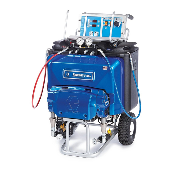
Instructions-Parts
Reactor
For spraying or dispensing polyurea coatings and polyurethane foam. For professional
use only.
Not approved for use in explosive atmospheres or hazardous locations.
3000 psi (21 MPa, 207 bar) Maximum Working Pressure
Important Safety Instructions
Read all warnings and instructions in this
manual. Save these instructions.
®
E-10hp
332144E
EN
ti21488a
Advertisement
Table of Contents

Related Manuals for Graco Reactor E-10hp


Summary of Contents for Graco Reactor E-10hp
- Page 1 Instructions-Parts ® Reactor E-10hp 332144E For spraying or dispensing polyurea coatings and polyurethane foam. For professional use only. Not approved for use in explosive atmospheres or hazardous locations. 3000 psi (21 MPa, 207 bar) Maximum Working Pressure Important Safety Instructions Read all warnings and instructions in this manual.
-
Page 2: Table Of Contents
Refill Tanks ....... 23 Graco Standard Warranty ....78 Pressure Relief Procedure . -
Page 3: Warnings
Warnings Warnings The following warnings are for the setup, use, grounding, maintenance, and repair of this equipment. The exclama- tion point symbol alerts you to a general warning and the hazard symbols refer to procedure-specific risks. When these symbols appear in the body of this manual or on warning labels, refer back to these Warnings. Product-specific hazard symbols and warnings not covered in this section may appear throughout the body of this manual where applicable. - Page 4 Warnings WARNING SKIN INJECTION HAZARD High-pressure fluid from gun, hose leaks, or ruptured components will pierce skin. This may look like just a cut, but it is a serious injury that can result in amputation. Get immediate surgical treatment. • Engage trigger lock when not spraying.
- Page 5 Warnings WARNING EQUIPMENT MISUSE HAZARD Misuse can cause death or serious injury. • Do not operate the unit when fatigued or under the influence of drugs or alcohol. • Do not exceed the maximum working pressure or temperature rating of the lowest rated system component.
-
Page 6: Important Isocyanate (Iso) Information
Important Isocyanate (ISO) Information Important Isocyanate (ISO) Information Isocyanates (ISO) are catalysts used in two component materials. Isocyanate Conditions Spraying or dispensing fluids that contain isocyanates creates potentially harmful mists, vapors, and atom- ized particulates. • Read and understand the fluid manufacturer’s warnings and Safety Data Sheet (SDS) to know specific hazards and precautions related to isocyanates. -
Page 7: Material Self-Ignition
Important Isocyanate (ISO) Information For all applications except spray foam Keep Components A and B Separate Spraying or dispensing fluids that contain isocyanates creates potentially harmful mists, vapors, and atomized Cross-contamination can result in cured material in fluid particulates. lines which could cause serious injury or damage equipment. -
Page 8: Foam Resins With 245 Fa Blowing Agents
Important Isocyanate (ISO) Information Foam Resins with 245 fa Blowing Agents Some foam blowing agents will froth at temperatures above 90°F (33°C) when not under pressure, especially if agitated. To reduce frothing, minimize preheating in a circulation system. Changing Materials NOTICE Changing the material types used in your equipment requires special attention to avoid equipment damage... -
Page 9: Systems
Systems Systems Maximum Working Pressure, Unheated Proportioner Hose Cord Volts Part (MPa, bar) Model 35 ft (10.6 m) Adapter Model Part 3000 ® APT100 100-120VAC 24T100 25R000 249810 Fusion Air Purge (21, 207) 3000 ® P2T100 100-120VAC 24T100 25R000 GCP2RA PROBLER (21, 207) 3000... -
Page 10: Related Manuals
Related Manuals Related Manuals The following manuals are for Reactor E-10hp components and accessories. Some are supplied with your package, depending on its configuration. Manuals are also available at www.graco.com. Displacement Pump Part No. Description 311076 Instruction-Parts Manual (English) Fusion Air Purge Spray Gun Part No. -
Page 11: Overview
• Good for touchup or low flow spraying, up to moder- ate temperature. The Reactor E-10hp is gravity-fed from 6 gal. (22.7 liter) • Not used to circulate full tanks up to temperature. supply tanks mounted on the unit. -
Page 12: Component Identification
Component Identification Component Identification Key for F Supply Tank (ISO) Desiccant Dryer Supply Tank (RES) Recirculation Tubes Pump (ISO) Q Air Line Inlet (quick-disconnect fitting) Pump (RES) Outlet Hose Connections Heater (under shroud) Return Hose Connections Fluid Pressure Gauges Fluid Temperature Sensors (located on heater G Recirc/Spray and Overpressure Relief Valves assembly, under shroud) H Tank Level Sensors (bottom of tanks) -
Page 13: Controls And Indicators
Controls and Indicators Controls and Indicators NOTICE To prevent damage to soft key buttons, do not press See Controls and Indicators identification table, page the buttons with sharp objects such as pens, plastic cards, or fingernails. Heater Controls ° ° . -
Page 14: Controls And Indicators
Controls and Indicators Controls and Indicators Name Description Heater Controls ISO Setpoint Increase Increases the temperature setpoint by one degree in the units selected within the setpoint limits. Press target key prior to adjusting. ISO Setpoint Decrease Decreases the temperature setpoint by one degree in the units selected within the setpoint limits. - Page 15 Controls and Indicators Motor/Pump Control Function Knob Heater Control Diagnostic Codes Heater control diagnostic codes appear on the tempera- Use knob (AV) to select desired function ture display. These alarms turn off heat. Icon Setting Function Table 2: Heater Control Diagnostic Codes Stops motor and automati- Stop/Park cally parks pumps.
-
Page 16: Setup
Setup Setup Locate Reactor 1. Locate Reactor on a level surface. To avoid electric shock, always unplug both cords 2. Do not expose Reactor to rain. before servicing Reactor and wait one minute. Electrical Requirements Heater Power Improper wiring may cause electric shock or other serious injury if work is not performed properly. -
Page 17: Ground System
Setup Ground System 2. Connect recirculation hoses from gun recirculation ports to connections (S). The equipment must be grounded to reduce the risk of static sparking and electric shock. Electric or static sparking can cause fumes to ignite or explode. Improper grounding can cause electric shock. -
Page 18: Fill Wet-Cups
(red side, with desiccant filter in cover). Keep the felt washers in the pump wet-cups saturated Replace cover with Graco ISO pump oil, Part No. 217374. The lubricant creates a barrier between the ISO and the atmosphere. Pump rod and connecting rod move during operation. -
Page 19: Purge Air And Flush Fluid From Lines
Setup Purge Air and Flush Fluid From 5. Turn on Motor Power. System status indicator (AY) should turn on. Lines To avoid fire and explosion: 6. Set Recirc/Spray valves to Recirc. • Flush equipment only in a well-ventilated area. • Ensure main power is off and heater is cool before flushing. -
Page 20: Startup
Startup Startup d. Press to display actual temperatures. Heated fluid can cause equipment surfaces to 5. Circulate through heater until temperature readouts become very hot. To avoid severe burns: display desired temperature. See Table 6. • Do not operate Reactor without all covers and 6. -
Page 21: Heatup Guidelines
Startup Heatup Guidelines Heat Management Tips The fluids must be circulated from the pumps through • Heaters perform better with lower flow rates or the heater, hoses, and back to the tanks to ensure warm smaller mix modules. fluids are supplied to the gun. •... -
Page 22: Spraying
Spraying Spraying 4. Check fluid pressure gauges to ensure proper pres- sure balance. If imbalanced, reduce pressure of higher component by slightly turning Recirc/Spray valve for that component toward Recirc, until NOTE: Air is supplied to spray gun with gun piston gauges show balanced pressures. -
Page 23: Pause
Pause Pause Refill Tanks To bring the hose and gun back to spray temperature Material can be added to the tanks at any time. See Fill after a brief break, use the following procedure. Fluid Tanks, page 18. 1. Engage piston safety lock or trigger safety lock. NOTE: If you are operating at high temperatures or flow rates, follow Pause instructions to bring tanks up to tem- perature. -
Page 24: Pressure Relief Procedure
Pressure Relief Procedure Pressure Relief Shutdown Procedure NOTE: For longer breaks (more than 10 minutes) use the following procedure. If you will be shutdown for more Follow the Pressure Relief Procedure whenever than 3 days, first see Flushing, page 26. you see this symbol. -
Page 25: Maintenance
Maintenance Maintenance • Check pump wet-cups fluid level daily, page 18. • Throat u-cup is not adjustable. Do not overtighten packing nut/wet-cup. • Keep component ISO from exposure to moisture in atmosphere, to prevent crystallization. • Wipe supply tank lid o-ring, inner rim, and inner tank walls daily to prevent ISO crystallization. -
Page 26: Flushing
Flushing Flushing 3. Shut off Heater Power. Allow system to cool. To avoid fire and explosion: • Flush equipment only in a well-ventilated area. • Ensure main power is off and heater is cool before 4. Remove recirculation tubes (P) from supply tanks flushing. -
Page 27: Purge Hoses
Flushing through system to waste containers. 13. Solvent flushing is a two step process. Go back to step 4, drain solvent, and flush again with fresh sol- vent. 14. Leave unit filled with solvent, plasticizer, clean ti31496a motor oil, or refill supply tanks with new material and reprime. -
Page 28: Troubleshooting
Troubleshooting Troubleshooting Pump Control Status Codes To turn off automatic shutdown and/or change pressure tolerances for status code 2, see DIP Switch Settings, page 30. Determine the status code by counting the number of times the system status indicator blinks. The status indi- Deviation can occur if power is turned on if function cator will blink 1-19 times to indicate a status code. - Page 29 Troubleshooting Status Code 6: High Motor Temperature 3. Check J6 connections on control board. See Table 8, page 46. Motor is running too hot. Level Sensor 1. Reduce pressure duty cycle, gun tip size, or move Status Reactor to a cooler location. Allow 1 hour for cool- Green - on Sensor is powered ing.
-
Page 30: Dip Switch Settings
Troubleshooting DIP Switch Settings To avoid electric shock, always unplug both power cords before servicing Reactor and wait one minute. 1. Turn power off and unplug power cords from wall outlets. 2. Remove screws and display cover (26). ti21923a 3. Locate the DIP switch on the control board. . - Page 31 Troubleshooting DIP Switch Settings and Functions DIP Switch Settings and Functions DIP Switch and Function DIP Switch 1 DEVIATION DEVIATION AND If selected, displays a status code or displays a status code SHUTDOWN and causes shutdown if the pressure imbalance exceeds selection made in DIP Switch 2.
-
Page 32: Heat Control Diagnostic Codes
Troubleshooting Heat Control Diagnostic Codes • Failed heater element where thermocouple is installed. Heat control diagnostic codes appear on the tempera- • Loose wire ture display. E01 Checks These alarms turn off heat. Codes E03 and E04 can be cleared by pressing Troubleshooting this equipment requires access to 1. - Page 33 Troubleshooting 4. Remove connector B from heater control module 5. Verify fluid temperature, using an external tempera- and check continuity of thermocouples by measur- ture sensing device. ing resistance across pins on the plug end. Table 7: Connector B Resistance Measurements 120V 230V Reading...
-
Page 34: Reactor Electronics
Troubleshooting Reactor Electronics 2. Shut off Motor Power. 3. Relieve pressure, page 24. Before performing any troubleshooting procedures: 4. Allow equipment to cool. 1. Shut off Heater Power. 5. Try the recommended solutions in the order given for each problem, to avoid unnecessary repairs. Also, determine that all circuit breakers, switches, and controls are properly set and wiring is correct before assuming there is a problem. - Page 35 Troubleshooting PROBLEM CAUSE SOLUTION Display does not respond properly to Poor display connection. Check cable connections, F . 23 on button pushes. page 73. Replace damaged cable. Display cable damaged or corroded. Clean connections, F . 23 on page 73. Replace damaged cable. Ribbon cable on display circuit board Connect cable, F .
-
Page 36: Heaters
Troubleshooting Heaters 2. Shut off Motor Power. Before performing any troubleshooting procedures: 3. Relieve pressure, page 24. 1. Shut off Heater Power. 4. Allow equipment to cool. Try the recommended solutions in the order given for each problem, to avoid unnecessary repairs. Also, determine that all circuit breakers, switches, and con- trols are properly set and wiring is correct before assum- ing there is a problem. -
Page 37: Proportioner
Troubleshooting Proportioner 2. Shut off Motor Power. Before performing any troubleshooting procedures: 3. Relieve pressure, page 24. 1. Shut off Heater Power. 4. Allow equipment to cool. Try the recommended solutions in the order given for each problem, to avoid unnecessary repairs. Also, determine that all circuit breakers, switches, and con- trols are properly set and wiring is correct before assum- ing there is a problem. - Page 38 Troubleshooting PROBLEM CAUSE SOLUTION One side doesn’t come up to pres- Low fluid in tank. Refill. sure in spray mode. Dirty or damaged Recirc/Spray valve. Clean or repair, page 41. Plugged fluid inlet strainer. Clear, see page 25. Pump intake valve plugged or stuck Clean pump intake valve.
- Page 39 Troubleshooting PROBLEM CAUSE SOLUTION ISO side rich; lack of RES side. ISO side gauge is low. RES side restriction downstream of gauge. Check gun check valve screen, mix module, or mix manifold restrictor. RES side gauge is low. RES side material supply problem. Check RES side inlet strainer and pump intake valve.
-
Page 40: Repair
Repair Repair Before Beginning Repair Remove Supply Tank Repairing this equipment requires access to parts 1. See Before Beginning Repair, page 40. which may cause electric shock or other serious injury if work is not performed properly. Have a 2. Relieve pressure, page 24. qualified electrician connect power and ground to main power switch terminals, see page 16. -
Page 41: Replace Recirc/Spray Valves
Repair 8. Disconnect swivel elbow at pump fluid inlet. Replace Recirc/Spray Valves 9. Remove six screws (28) holding tank (27) to cart frame. 1. See Before Beginning Repair, page 40. 2. Relieve pressure, page 24. 3. See F . 7. Disassemble Recirc/Spray valves. Clean and inspect all parts for damage. -
Page 42: Displacement Pump
Repair Displacement Pump 8. Remove pump rod cover (222). Push clip up in back and push pin (217) out. Loosen locknut (218) by hit- ting firmly right-to-left with a non-sparking hammer. NOTE: Use dropcloth or rags to protect Reactor and Unscrew pump. -
Page 43: Control Panel
Repair Control Panel Replace Function Knob/Potentiometer Replace Temperature Display 1. See Before Beginning Repair, page 40. 2. Remove screws (21) and back cover (26). NOTICE 3. Disconnect potentiometer wires from J5 on motor Before handling board, put on a static conductive control board (354). - Page 44 Repair ti21841a . 10: Control Panel 332144E...
-
Page 45: Motor Control
Repair Motor Control Replace Control Board Power Bootup Check NOTE: Power must be on to check. See F . 11 or loca- tion. Function is: NOTE: Check motor before replacing board. See Test Motor, page 54. • Motor ready: LED on. •... - Page 46 Repair Table 8: Control Board Connectors (see F . 12) Top Board Connectors Bottom Board Connectors Board Jack Description Connector Description Not Used Female Quick Power Connect Terminals Not Used Plug Housing with Motor Power Male Blades Error LED Tank Level LED Function Knob Brown - ISO Sensor V+ Blue - ISO Sensor V-...
- Page 47 Repair Replace Temperature Control Modules 4. Disconnect all cables and connectors from tempera- ture control module (59). NOTICE Before handling assembly put on a static conductive wrist strap to protect against discharge which can damage assembly. Follow instructions provided with wrist strap.
- Page 48 Repair Temperature Control Modules Connections Table 9: Heater Control Module Connections Table 9: Heater Control Module Connections Description Connector 100-120VAC 200-240VAC Description POWER/RELAY (G) Circuit board power input and Connector 100-120VAC 200-240VAC contactor control output DATA (A) Not used Table 10: Temperature Power Module Connections Sensor (B) See Table 11 DISPLAY (C)
-
Page 49: Heater
Repair Heater 4. Disconnect heater element wires from heater wire connector. Test with ohmmeter. Replace heater ele- ment if the resistance reading does not fall within Test Heater Element the range. Nominal Heater Heater Wattage Per Element Voltage Zone Wattage Ohms 1. - Page 50 Repair Thermocouple 8. Replace thermocouple, F . 16. 1. See Before Beginning Repair, page 40. a. Remove protective tape from thermocouple tip (T). b. Apply PTFE tape and thread sealant to male threads and tighten thermocouple housing (H) 2. Wait for heaters to cool. into adapter (305).
-
Page 51: Pressure Transducers
Repair Overtemperature Switch 4. Replace transducer if the transducer fails test. 1. See Before Beginning Repair, page 40. a. Remove supply tank, page 40. b. Follow transducer cable on cart frame and cut zip ties. Disconnect transducer from pump out- let manifold. -
Page 52: Drive Housing
Repair Drive Housing 4. Install gear reducer (214) and crankshaft (210) into motor end bell (MB). NOTE: Crankshaft (210) must be in line with crankshaft at other end of motor. Pumps will move up and down together. Removal NOTE: If connecting rod (216) or pump (219) were 1. -
Page 53: Replace Cycle Counter Switch
Repair Replace Cycle Counter Switch NOTE: RES side drive housing cover (229) includes the cycle counter switch (223), mounted in the cover. When reassembling, be sure to install cover with switch on RES side. 0.6 in. (15.2 mm) from inside edge 1.0 in. -
Page 54: Electric Motor
Repair Electric Motor NOTICE To prevent dropping the motor, two people may be Test Motor required to lift. If motor is not locked up by pumps, it can be tested using a 9 V battery. 10. Remove screws (15) holding motor (201) to bracket. Lift motor off unit. -
Page 55: Motor Brushes
Repair Motor Brushes 9. See instruction sheet 406582, included with Brush Repair Kit 287735. NOTE: Replace brushes worn to less than 1/2 in. (13 mm). Brushes wear differently on each side of motor; check both sides. Brush Repair Kit 287735 is available; kit includes instruction sheet 406582. -
Page 56: Tank Fluid Level Sensors
Repair Tank Fluid Level Sensors 6. Route new tank level sensor cable through grommet on bottom of cart and through the grommet on bot- tom of control panel. Connect new level sensor (57) Adjust to J6. Adjust position of tank fluid level sensor (57) so that the 7. - Page 57 Repair Reset Sensitivity 7. Slowly turn the adjustment screw (S) counterclock- wise an additional 1/2 turn. The tank fluid level sensor sensitivity may need to be adjusted when: NOTE: The yellow LED should stay turned off. • A new tank has a different insulation density than 8.
-
Page 58: Parts
Parts Parts System Packages 16W239 15G958 15G962 Proportioner Hose Power Cord Adapter System Package see page 59 see page 72 Part No. Region ✖ ✖ APT100 24T100 25R000 249810 ✖ ✖ P2T100 24T100 25R000 GCP2RA* APT900 24R900 25R000 249810 16W239 North America APT901 24R900... -
Page 59: E-10Hp Proportioners
Parts E-10hp Proportioners 24T100, 100-120VAC, Proportioner 24R900, 200-240VAC, Proportioner 30, 30a ti21853b 332144E... - Page 60 Parts ti21855b 332144E...
- Page 61 Parts 45 46 ti21854a 332144E...
- Page 62 Parts Apply sealant to all non-swiveling pipe threads. Orient SSR with terminals 1 and 2 towards the top. Apply sealant to threads of nut cap. Orient fan to flow down and connector plug towards the back. Apply lubricant to thread and axle of cart. Orient heater module with fins outwards.
- Page 63 Parts Quantity 24T100, 24R900, 100-120 200-240 Ref. Part Description 24R648 COVER, display 24T973 TANK 111800 SCREW, cap, hex hd 127148 SCREW, set, 7/16-14, 1/2, black 24T975 LID; includes o-ring (30a) 24T974 O-RING 24K976 MUFFLER,1/4 NPT 101044 WASHER, plain 119973 CABLE, sst lanyard; 14 in. 24K984 DRYER, desiccant, mini in-line 162453...
- Page 64 Parts Quantity 24T100, 24R900, 100-120 200-240 Ref. Part Description 114225 TRIM, edge protection 119992 FITTING, pipe, nipple, 3/4 x 3/4 npt 24T982 MANIFOLD, inlet, RES; see page 70 24T986 MANIFOLD, inlet, ISO; see page 70 24T987 COVER, electronics 115942 NUT, hex, flange head 24T988 SENSOR, tank level 24T990...
- Page 65 Parts Quantity 24T100, 24R900, 100-120 200-240 Ref. Part Description 24T993 RELAY, 12V 255043 HOLDER, fuse terminal block; 5 x 20mm 255023 FUSE, 5A, 5 x 20 mm 74† 127239 CONNECTOR, 5 pin 127240 CONNECTOR, 10 pin 75† 120748 CONNECTOR, 2 pin 127237 CONNECTOR, 6 pin 116171...
- Page 66 Parts 24T954, 100-120VAC and 200-40VAC Bare Proportioner 207 233 (steel) (bronze) (ref) (bronze) (ref) (steel) (bronze) (bronze) ti21847a 0.6 in. (15.2 mm) from inside edge 1.0 in. (25.4 mm) from inside bottom edge TI7028a Apply lubricant to all gear teeth, motor pinion, and motor Torque fasteners to 30-35 in.-lbs.
- Page 67 Parts Ref. Part Description 24T758 MOTOR, electric 207‡ 115492 SCREW, mach, slot hex wash 208* 116074 WASHER, thrust 209* 107434 BEARING, thrust 210* 300001 KIT, crankshaft 211* 180131 BEARING, thrust 212† 116073 WASHER, thrust 213† 116079 BEARING, thrust 214† 244242 GEAR, reducer (first stage) 215‡...
- Page 68 Parts 24U009, 100-120VAC Heater 24T955, 200-240VAC Heater ti21850a Torque to 120 ft-lbs (163 N•m). Apply lubricant to o-rings before assembling in heater housing. Torque to 23 ft-lbs (31 N•m). Tighten NPT fitting from sensor to heater housing as shown. Remove tape from probe tip prior to inserting. Insert probe Apply 110009 thermal heat sink compound.
- Page 69 Parts 24T962, Display ti21841a Ref. Part Description Qty. Ref. Part Description Qty. 24T971 DIODE, light-emitting, yellow 24T963 PLATE, display, front CLAMP, cable 24T964 ENCLOSURE, control 113505 NUT, keps, hex hd 24T966 DISPLAY, heat two zone 101765 GROMMET 24T967 CONTROL, board, assy 127019 CONNECTOR, jumper, e-stop 24K983 SWITCH, rocker, w/breaker, 240v, 24L001 KNOB, control, w/ball plunger...
- Page 70 Parts Fluid Inlets 24T986, ISO Inlet 24T982, RES Inlet Align Y-strainer as shown Apply sealant to all npt threads. Do not apply to JIC threads. Apply thermal lubricant to thermometer probe. Torque fitting of bent tube to 45-50 ft-lbs (61-67 N•m). Align bent tube to fitting within 2°.
- Page 71 Parts 24T960, Fluid Manifold Apply sealant to assembled non-swiveling pipe threads. Apply sealant and PTFE tape to threads. Apply sealant to valve threads. Torque to 240-260 in.-lbs (27-29 N•m). Apply lubricant to mating surfaces of valve base and handle. Apply lubricant to o-rings on fittings. Torque to 16-20 ft-lbs (22-27 N•m).
- Page 72 Parts 25R000, Insulated Hose Bundle with Recirculation Lines 502 (Ref) 503 (Ref) TI6991a Ref. Part Description Ref. Part Description 15G342 HOSE, air; 1/4 in. (6 mm) ID; 1/4 24R996 HOSE, fluid (component ISO), npsm (fbe); 35 ft (10.7 m) moisture guard; 1/4 in. (6 mm) ID; TUBE, foam, insulated;...
- Page 73 Parts . 23: Power Harness (78) Wire Identification 332144E...
- Page 74 Parts . 24 332144E...
-
Page 75: Suggested Replacement Parts
Suggested Replacement Parts Suggested Replacement Accessories Parts Part Description 24E727 Probler Recirc Kit Part Description 24U342 Lift Ring Kit 24K984 DRYER, desiccant 24K983 SWITCH, motor or heater power, with circuit breaker 101078 Y-STRAINER; includes 180199 element 180199 ELEMENT, Y-strainer, 20 mesh 114228 ELEMENT, air filter, 5 micron;... -
Page 76: Technical Data
Technical Data Technical Data Reactor E-10hp Metric Maximum fluid working pressure 3000 psi 20.6 MPa, 206 bar Maximum spray pressure: 120 V 2200 psi 15.2 MPa, 152 bar Maximum spray pressure: 230 V 2500 psi 17.2 MPa, 172 bar Maximum fluid temperature 170°F... - Page 77 Technical Data Reactor E-10hp Metric Fluid Outlets ISO Side -5 JIC male RES Side -6 JIC male Fluid Circulation Returns ISO side -5 JIC male RES side -6 JIC male Hose Markings ISO side RES side Blue Wetted Parts Wetted parts on all models...
-
Page 78: Graco Standard Warranty
With the exception of any special, extended, or limited warranty published by Graco, Graco will, for a period of twelve months from the date of sale, repair or replace any part of the equipment determined by Graco to be defective.