Table of Contents
Advertisement
Advertisement
Table of Contents

Related Manuals for Motorola AP-7562


Summary of Contents for Motorola AP-7562
- Page 1 AP-7562 ACCESS POINT INSTALLATION GUIDE...
- Page 2 AP-7562 Access Point Zebra and the Zebra head graphic are registered trademarks of ZIH Corp. The Symbol logo is a registered trademark of Symbol Technologies, Inc., a Zebra Technologies company. © 2015 Symbol Technologies, Inc...
-
Page 3: Table Of Contents
1.10.1 AP-7562 Ports and Connections....... . 13 1.10.2 AP-7562 Antenna Connectors ....... . . 14 1.10.3 AP-7562 Antenna Mounting Guidelines . - Page 4 8.0 AP-7562 Series ROHS Compliance ........64...
- Page 5 Installation Guide...
-
Page 6: Introduction
Input Multiple Output (MIMO) dual radio design together with rugged outdoor performance. The AP-7562 is a 3x3:3 802.11ac Access Point utilizing one 2.4 GHz 802.11n radio and one 5 GHz 802.11ac radio. The AP-7562 is optimized with WiNG intelligence, extending QoS, security, and mobility services to the Access Point to support better capacity and performance. -
Page 7: Ap-7562 Hardware
1.3 AP-7562 Antenna Accessories Antennas must be ordered separately and are not included with the AP-7562. NOTE The AP-7562 antenna suite includes the following optional antenna accessories. The antennas do not ship with the AP-7562 Access Points and must be ordered separately. -
Page 8: Ap-7562 Dual Band 2.4 Ghz / 5 Ghz Antennas - Us And Canada
AP-7562 Access Point 1.3.1 AP-7562 Dual Band 2.4 GHz / 5 GHz Antennas - US and Canada Part Number Antenna Type 2.4 GHz Peak Gain 5.2 GHz Peak Gain ML-2452-HPAG4A6-01 Dipole ML-2452-HPA6X6-036 Dipole ML-2452-HPA6-01 Dipole ML-2452-PNA5-01R Panel ML-2452-PNL3M3-1 Polarized Panel 1.3.2 AP-7562 Single Band 2.4 GHz Antennas - US and Canada... -
Page 9: Outdoor Elevation Gain Configuration For Us Skus
Dipole ML-5299-HPA5-01 -2.53 Dipole ML-2452-HPAG4A6-01 Dipole ML-2452-HPA6X6-036 Dipole ML-2452-HPA6-01 4.09 1.3.5 AP-7562 Dual Band 2.4 GHz / 5 GHz Antennas - EU Part Number Antenna Type 2.4 GHz Peak Gain 5.2 GHz Peak Gain ML-2452-HPAG5A8-01 Dipole ML-2452-PNA7-01R Panel 12.0 ML-2452-PNL3M3-1 Polarized Panel 1.3.6 AP-7562 Single Band 2.4 GHz Antennas - EU... -
Page 10: Hardware And Mounting Accessories
1.4 Hardware and Mounting Accessories The AP-7562 is a Power over Ethernet (PoE) device. When deployed, the use of an outdoor rated PoE power supply and mounting bracket may be required. The recommended PoE accessories are listed in the following table:... -
Page 11: Package Contents
Refer to when verifying all AP-7562 hardware has been received. Record the serial numbers on the shipping cartons and AP-7562 for warranty claims and reference during software download procedures. Record the serial numbers on the shipping cartons and AP-7562 Access Points for NOTE warranty claims and reference during software download procedures. -
Page 12: Precautions
• The installation professional should be familiar with all grounding requirements and regional codes and ensure the Access Point and mounting asset are properly grounded. The grounding cable for an AP-7562 must be at a minimum a #10 gauge wire cross section. The cable can be attached to the unit using one of the following methods: •... -
Page 13: Warnings
Installation Guide 1.8.2 Warnings • Read all installation instructions and site survey reports, and verify correct equipment installation before connecting the Access Point to its power source. • Remove jewelry and watches before installing this equipment. • Verify the unit is grounded before connecting it to the power source. •... -
Page 14: Access Point Placement
1.10 AP-7562 Hardware Overview The AP-7562 is a 3x3:3 802.11ac Access Point utilizing one 2.4 GHz 802.11n radio and one 5 GHz 802.11ac radio. An AP-7562 must be installed by trained professionals familiar with RF planning and regulatory limits defined by the regulatory bodies of the country where the devices are being deployed. -
Page 15: Ap-7562 Antenna Connectors
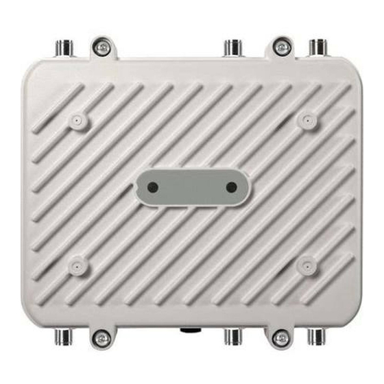
Installation Guide 1.10.2 AP-7562 Antenna Connectors AP-7562 Access Points (AP-7562-67040-US, AP-7562-67040-EU and AP-7562-67040-WR) are configured with six N type connectors to support two active WLAN data radios. Antenna ports where no antenna is mounted must be properly terminated using an WARNING! approved IP67 terminator. -
Page 16: Ap-7562 Antenna Mounting Guidelines
AP-7562 Access Point 1.10.3 Antenna Mounting Guidelines The following are examples of acceptable mounting for dipole antenna deployments: The following are examples of acceptable mounting methods for panel antenna deployments:... -
Page 17: Ap-7562 Grounding Post
Installation Guide 1.10.4 AP-7562 Grounding Post The grounding post is located on the bottom of the Access Point above the GND symbol. The grounding cable for an AP-7562 must be at a minimum a #10 gauge wire cross WARNING! section. -
Page 18: Vmm Mounting And Installation
(KT-158767-01) for mobile deployments. To install the Access Point VMM: 1. Remove rubber plugs from four screw holes on the LED side of the AP-7562. Position unit with screw holes facing upwards. 2. Put the flat plate on top of the VMM. Align the key hole and four screw holes on the flat plate with the philips screw head and four screw holes on the VMM. - Page 19 Installation Guide 4. Put the stiffener plate on the chassis mount with the key hole and four screw holes aligned. 5. Insert four screws with washers through the holes of the three plates and into the screw holes on the bottom of the VMM.
- Page 20 9. Attach the vehicle mount securely to the mount point with metal screws or bolts (not provided). 10. Securely attach the AP-7562 top bracket sub-assembly to the vehicle mount with the four pre-installed thumb screws. Tighten the screws to 90 inch pounds (lbf-in) using a philips screwdriver or pliers.
- Page 21 Installation Guide VMM Power Options A mounted AP-7562 operating as a VMM within a vehicle or mobile asset requires a power source delivered via Power over Ethernet (PoE). A professional certified installation partner should be consulted in respect to appropriate power sources and installation within a vehicle or mobile asset. A vehicular power source is not provided.
-
Page 22: Led Indicators
1.12 LED Indicators AP-7562 Access Points have LED activity indicators on the front of the enclosure. The LEDs provide a status display indicating error conditions, transmission, and network activity for the 2.4 GHz radio (green) and the 5 GHz radio (amber). -
Page 23: Ap-7562 Hardware Mounting And Installation
(KT-150173-01). 2.1 Mounting Bracket Kit The AP-7562 mounting bracket kit (KT-147407-01) includes the Access Point bracket (left), angle adapter bracket (center), and pole mount bracket (right) sections: The Access Point bracket and angle adapter bracket can be rotated (plus or minus 15 degrees) and tilted (up to 45 degrees) to orient the unit for optimal positioning. -
Page 24: Extension Arm Kit
AP-7562 Access Point 2.1.1 Extension Arm Kit When mounting an AP-7562 on poles more than 3 inches in diameter, use the extension arm kit (KT-150173-01) to provide a minimum standoff distance of twelve inches to avoid interference with the antennas. -
Page 25: Pole Mounted Installations
2.2 Pole Mounted Installations The mounting hardware kit and extension arm can be used in various combinations to properly install the AP-7562 on a pole. For poles of up to 3 inches in diameter, attach the pole mount bracket of the mounting hardware kit at the desired position on the pole using band clamps up to 3/4 inch width, or a 1/2 inch x 4 inch wide U-bolt and nuts. -
Page 26: Vertical Pole Mount
AP-7562 Access Point 2.2.1 Vertical Pole Mount Use the following procedure for vertical pole mount installations. The extension arm is recommended when mounting the Access Point to poles greater than 3 inches is diameter. For poles up to 3 inches in diameter when using a U-bolt: 1. - Page 27 AP with the gore vent. Using a torque wrench or a ratchet and a 10mm socket, or an adjustable wrench, attach (but don’t tighten) the Access Point bracket to the AP-7562 with the four M6 flange screw.
- Page 28 AP-7562 Access Point 6. With the Access Point positioned so the gore vent is facing down, insert the two M6 hex flange screws in the bottom holes on the sides of the Access Point bracket into the open slot connections on the bottom of the angle adapter bracket.
- Page 29 AP with the gore vent. Using a torque wrench or a ratchet and a 10mm socket, or an adjustable wrench, attach (but don’t tighten) the Access Point bracket to the AP-7562 with the four M6 hex flange screws.
- Page 30 AP-7562 Access Point 6. Rotate the Access Point bracket upward and align the top holes on the sides with the top holes on the angle adapter bracket. Insert two M6 hex flange screws into the top holes on the angle adapter bracket.
- Page 31 Installation Guide 3. Using a torque wrench or a ratchet and a 10mm socket, or an adjustable wrench, attach the extension arm to the Access Point bracket with four M6 hex flange screws. The two oval holes must be positioned on the short sides of the Access Point.
-
Page 32: Wall Mounted Installations
2. Using a torque wrench or a ratchet and a 10mm socket, or an adjustable wrench, attach (but don’t tighten) the Access Point bracket to the AP-7562 with four M6 hex flange screws and insert two M6 hex flange screws into the bottom holes on the sides of the Access Point bracket. - Page 33 Installation Guide 3. With the Access Point positioned so the gore vent is facing down, insert the two M6 hex flange screws in the bottom holes on the sides of the Access Point bracket into the open slot connections on the bottom of the angle adapter bracket.
-
Page 34: Ap-7562 Power Options Using Power Over Ethernet
NOTE injector. If located within 100 meters of the controller and a PoE port is available, the AP-7562 Access Point can also be connected directly to a WLAN or Integrated Services Controller running WiNG 5.6 or higher. A standard CAT5E cable can be used to provide the connection to the AP-7562. The GE1/POE port on the AP-7562 is where the standard CAT5E cable will connect to the Access Point and use of the weatherproof RJ45 plug kit that comes with the unit will maintain a weatherproof seal for outdoor installation at the ethernet port. -
Page 35: Basic Access Point Configuration
Installation Guide 3 Basic Access Point Configuration Once the Access Point is installed and powered on, complete the following steps to get the device up and running and access management functions: 1. The Access Point’s IP address is optimally provided using DHCP or from bottom of the Access Point itself (if available). - Page 36 AP-7562 Access Point If this is the first time the interface has been accessed, a screen displays prompting for the Access Point’s country code. 6. Select the Country Code specific to this Access Point’s deployment location. Selecting the correct country is central to legal operation. Each country has its own regulatory restrictions concerning electromagnetic emissions and the maximum RF signal strength that can be transmitted.
- Page 37 Installation Guide 8. Set the following Basic Configuration Settings for this Access Point: • AP Name - Provide an AP Name used as this Access Point’s network identifier. If setting this Access Point as a Virtual Controller, each Access Point managed by this Virtual Controller lists this Access Point’s AP Name as its own.
- Page 38 AP-7562 Access Point 10. Expand the Configuration menu item and select WAN. 11. Refer to the WAN Settings field and set the following: • Enable - Select this option to allow a connection between the Access Point and a larger network or outside world through the WAN port.
- Page 39 Installation Guide • Static IP / Mask - Specify an IP address for the WAN connection if using static address assignment for the WAN port. An IP address uses a series of four numbers defined in dot notation, for example, 190.188.12.1.
- Page 40 AP-7562 Access Point 14. Select Apply to commit the updates to the selected Access Point’s configuration. 15. Expand the Configuration menu item and select Wireless. The Wireless screen displays fields where Radio Settings and Wireless LAN settings can be defined. Its recommended default radio settings remain as is for the Access Point’s basic setup.
- Page 41 Installation Guide 16. To create a new WLAN, select + Add from the upper, left-hand side of the Wireless LAN field. 17. Set the following configuration attributes for the new WLAN: • Name - Provide a unique name for the WLAN as its network identifier. This is a required setting. •...
- Page 42 AP-7562 Access Point If selecting Secure-802.1x, provide an IP address (or hostname) and a shared secret (password) used to access an external RADIUS server resource designated to validate user requests to the Access Point’s WLAN resources. Selecting Guest displays fields for captive portal Web page creation, and is beyond the scope of this basic Access Point configuration.
- Page 43 Installation Guide Select + Add and provide a starting and ending IP range of addresses that constitute a pool of addresses available to requesting clients. 21. Select Apply to commit the updates to the Access Point’s DHCP configuration. 22. At this point, you’re ready to connect to the network using the security restrictions applied to the newly created WLAN.
-
Page 44: Specifications
AP-7562 Access Point 4 Specifications 4.1 Physical Characteristics Dimensions 9.0 in. L x 10.0 in. W x 2.6 in. H 22.8 cm L x 25.4 cm W x 6.6 cm H Weight (Unit) 5.6lbs / 2.54 Kg Housing Outdoor IP67 rated, die-cast aluminum, corrosion resistant... -
Page 45: Power Characteristics
Installation Guide 4.3 Power Characteristics Operating Voltage 36-57 VDC Operating Current 375mA at 48V in 802.3at mode Integrated PoE 802.3af, 802.3at... -
Page 46: Regulatory Information
AP-7562 Access Point 5 Regulatory Information This device is approved under Zebra Technologies Corporation. All Zebra devices are designed to be compliant with rules and regulations in locations they are sold and will be labeled as required. Local language translations are available at the following website: www.zebra.com/support... -
Page 47: Frequency Of Operation - Fcc And Ic
Installation Guide 5.2 Frequency of Operation - FCC and IC 2.4 GHz Only The available channels for 802.11bg operation in the US are Channels 1 to 11. The range of channels is limited by firmware. The EIRP for all outdoor antennas used in the 5.15 - 5.25 GHz band should NOTE not exceed a maximum 125 mW ERIP (21dBm) at any elevation angle above 30 degrees (21dBm). -
Page 48: Rf Exposure Guidelines
AP-7562 Access Point Persons with Pacemakers: 1.Should ALWAYS keep the device more than 15cm (6 inches) from their pacemaker when turned ON. 2.Should not carry the device in a breast pocket. 3.Should use the ear furthest from the pacemaker to minimise the potential for interference. -
Page 49: Power Supply
Installation Guide US and Canada Co-located statement To comply with FCC RF exposure compliance requirement, the antenna used for this transmitter must not be co-located or operating in conjunction with any other transmitter/antenna except those already approved in this filling. To satisfy US and Canadian RF exposure requirements, a transmitting device must operate with a minimum separation distance of 35 cm or more from a person's body. -
Page 50: Radio Transmitters (Part 15)
This radio transmitter MODEL: AP-7562 has been approved by Industry Canada to operate with the antenna types listed below with the maximum permissible gain and required antenna impedance for each antenna type indicated. -
Page 51: Ce Marking And European Economic Area (Eea)
For more information consult the website http://www.anatel.gov.br. Declarações Regulamentares para AP-7562 - Brasil Nota: A marca de certificação se aplica ao Transceptor, modelo AP-7562. Este equipamento opera em caráter secundário, isto é, não tem direito a proteção contra interferência prejudicial, mesmo de estações do mesmo tipo, e não pode causar interferência a sistemas operando em caráter primário. - Page 52 AP-7562 Access Point Hong Kong In accordance with HKTA1039, the band 5.15GHz - 5.35GHz is for indoor operation only. Mexico Restrict Frequency Range to: 2.450 – 2.4835 GHz. La operación de este equipo está sujeta a las siguientes dos condiciones: (1) es posible que este equipo o dispositivo no cause interferencia perjudicial y (2) este equipo o dispositivo debe aceptar cualquier interferencia, incluyendo la que pueda causar su operación no deseada.
- Page 53 Installation Guide Taiwan 「電磁波曝露量 MPE 標準值 1mW/cm2,本產品使用時建議應距離人體:35 cm」 。 Ukraine Thailand...
- Page 54 AP-7562 Access Point 5.12 Waste Electrical and Electronic Equipment (WEEE) English: For EU Customers: All products at the end of their life must be returned to Zebra for recycling. For information on how to return product, please go to: www.zebra.com/weee.
-
Page 55: Turkish Weee Statement Of Compliance
Installation Guide Malti: Għal klijenti fl-UE: il-prodotti kollha li jkunu waslu fl-aħħar tal-ħajja ta' l-użu tagħhom, iridu jiġu rritornati għand Zebra għar-riċiklaġġ. Għal aktar tagħrif dwar kif għandek tirritorna l-prodott, jekk jogħġbok żur: www.zebra.com/weee. Românesc: Pentru clienţii din UE: Toate produsele, la sfârşitul duratei lor de funcţionare, trebuie returnate la Zebra pentru reciclare. -
Page 56: Support
AP-7562 Access Point 6 Support If you have a problem with your equipment, contact support for your region. Contact information is available at: www.zebra.com/support. When contacting support, please provide the following information: • Serial number of the unit • Model number or product name •... -
Page 57: Symbol Technologies End-User Software License Agreement
Installation Guide Symbol Technologies End-User Software License Agreement This End-User Software License Agreement ("End-User License Agreement") is between Symbol Technologies Inc. (herein "Symbol Technologies") and End-User Customer to whom Symbol Technologies' proprietary software or Symbol Technologies Products containing embedded, pre-loaded, or installed software ("Products") is made available. - Page 58 AP-7562 Access Point If the Software licensed under this End-User License Agreement contains or is derived from Open Source Software, the terms and conditions governing the use of such Open Source Software are in the Open Source Software Licenses of the copyright owner and not this End-User License Agreement. If there is a conflict between the terms and conditions of this End-User License Agreement and the terms and conditions of the Open Source Software Licenses governing End-User Customer’s use of the Open Source...
- Page 59 Installation Guide operated. End-User Customer may make as many copies of the Documentation as it may reasonably require for the internal use of the Software. Unless otherwise authorized by Symbol Technologies in writing, End-User Customer will not, and will not enable or allow any third party to: (i) install a licensed copy of the Software on more than one unit of a Product;...
- Page 60 AP-7562 Access Point 6. CONFIDENTIALITY End-User Customer acknowledges that the Software contains valuable proprietary information and trade secrets and that unauthorized dissemination, distribution, modification, reverse engineering, disassembly or other improper use of the Software will result in irreparable harm to Symbol Technologies for which monetary damages would be inadequate.
- Page 61 Installation Guide BE DISCLAIMED BY LAW, EVEN IF ADVISED OF THE POSSIBILITY OF SUCH DAMAGES. THE LIMITATIONS IN THIS PARAGRAPH WILL APPLY NOTWITHSTANDING ANY FAILURE OF ESSENTIAL PURPOSE OF ANY LIMITED REMEDY. 9. TERM AND TERMINATION Any use of the Software, including but not limited to use on the Products, will constitute End-User Customer’s agreement to this End-User License Agreement.
- Page 62 AP-7562 Access Point consistent with the rights provided to the End-User Customer under the provisions of the FAR and DFARS mentioned above, as applicable to the particular procuring agency and procurement transaction. 11. GENERAL 11.1 Copyright Notices. The existence of a copyright notice on the Software will not be construed as an admission or presumption that public disclosure of the Software or any trade secrets associated with the Software has occurred.
- Page 63 Installation Guide 11.8 Governing Law. This End-User License Agreement is governed by the laws of the the State of Delaware in the United States to the extent that they apply and otherwise by the internal substantive laws of the country to which the Software is shipped if End-User Customer is a sovereign governmental entity. The terms of the U.N.
-
Page 64: Ap-7562 Series Rohs Compliance
AP-7562 Access Point 8 AP-7562 Series ROHS Compliance 本表格依据 SJ/T 11364 的规定编制。 O:表示该有害物质在该部件所有均质材料中的含量均在 GB/T 26572 规定的限量 要求以下。 X:表示该有害物质至少在该部件的某一均质材料中的含量超出GB/T 26572 规定 的限量要求。(企业可在此处,根 据实际情况对上表中打“×”的技术原因进 行进一步说明。 ) This table was created to comply with China RoHS requirements. - Page 65 Installation Guide...
- Page 66 AP-7562 Access Point...
- Page 67 Installation Guide...
- Page 68 Zebra Technologies Corporation Lincolnshire, IL 60069 USA Zebra and the Zebra head graphic are registered trademarks of ZIH Corp. The Symbol logo is a registered trademark of Symbol Technologies, Inc., a Zebra Technologies company. © 2015 Symbol Technologies, Inc. MN002313A01 Revision A October 2015...