Oki MC160N User Manual
Oki all in one printer user manual
Hide thumbs
Also See for MC160N:
- Network manual (32 pages) ,
- User manual (101 pages) ,
- Network manual (32 pages)
Table of Contents
Advertisement
Quick Links
Advertisement
Table of Contents

Related Manuals for Oki MC160N


Summary of Contents for Oki MC160N
-
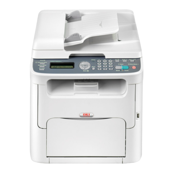
Page 1: User Guide
MC160n MFP User Guide Print/Copy/Scan Modes 59320401 my.okidata.com... -
Page 2: Copyright Information
The most up-to-date drivers and manuals are available from the web site: http://www.okiprintingsolutions.com Trademark Information _______________________________ Oki is a trademark of Oki Electric Industry Company Ltd. Apple, Macintosh and Mac OS are registered trademarks of Apple Computers Inc. Hewlett-Packard, HP, and LaserJet are registered trademarks of Hewlett-Packard Company. -
Page 3: Table Of Contents
Contents Introduction ........9 Getting Acquainted with Your Machine . - Page 4 COPY SETTING Menu ........63 DIAL REGISTER Menu ........65 FAX TX OPERATION Menu .
- Page 5 Using the Printer Driver ......101 Selecting Printer Driver Options/Defaults (for Windows) ..102 Displaying Printer Driver Settings .
- Page 6 Using the Scanner .......121 Scanning From a Computer Application ..... . . 122 Basic Scanning Operation .
- Page 7 Replacing Consumables ......151 Replacing Consumables ........152 About Toner Cartridges .
- Page 8 Installing Accessories ......247 Introduction ..........248 Tray 2 (Lower Feeder Unit) .
-
Page 9: Introduction
1Introduction... -
Page 10: Getting Acquainted With Your Machine
Getting Acquainted with Your Machine Space Requirements To ensure easy operation, consumable replacement and maintenance, adhere to the recommended space requirements detailed below. 160 mm 100 mm (3.9") 505 mm (19.9") 405 mm (15.9") Front View 405 mm (15.9") (6.3") 765 mm (30.1") Side View 10 Introduction... - Page 11 160 mm 430 mm (16.9") (6.3") 100 mm 947 mm (37.3") (3.9") Side View with Options (when Tray 2 and the duplex option are installed) The option appears shaded in the above illustrations. 11 Introduction 157 mm (6.2") 100 mm (3.9")
- Page 12 160 mm (6.3") 430 mm (16.9") 100 mm (3.9") 947 mm (37.3") Side View with Options (when the attachment and duplex option are installed) The option appears shaded in the above illustrations. 12 Introduction 157 mm (6.2") 100 mm (3.9")
-
Page 13: Part Names
Part Names The following drawings illustrate the parts of your machine referred to throughout this guide, so please take some time to become familiar with them. Front View 1–Control Panel 2–Automatic document Feeder (ADF) 2–a:ADF feed cover 2–b:Document guide 2–c:Document feed tray 2–d:Document output tray 2–e:Document stopper The ADF may appear as “docu-... -
Page 14: Rear View
11—Fuser unit 12—Fuser separator levers 13—Fuser cover lever 14—Imaging cartridge 15—Toner cartridge 16—Front cover Rear View 1–Power switch 2–Power connection 3–TEL (telephone) jack 4–LINE (telephone line) jack 5–USB port 6–10Base-T/100Base-TX (IEEE 802.3) Ethernet Interface port 14 Introduction... -
Page 15: Front View With Options
Front View with Options (when Tray 2 is installed) 1—Lower feeder unit (Tray 2) (when Tray 2 and duplex option are installed) 1—Duplex option 2—Lower feeder unit (Tray 2) (when the attachment and duplex option are installed) 1—Duplex option 2—Attachment 15 Introduction... -
Page 16: Rear View With Options
Rear View with Options (When Tray 2 is installed) 1—Lower feeder unit (Tray 2) 2—Locking pin (when Tray 2 and duplex option are installed) 1—Duplex option 2—Lower feeder unit (Tray 2) 16 Introduction... - Page 17 (when the attachment and duplex option are installed) 1—Duplex option 2—Attachment 17 Introduction...
-
Page 18: Cd Contents
Server 2008 for 64 bit Use/Benefit This software provides easy installa- tion of drivers and other software for your MC160n and also for changing the display and reporting language used. (Default is English.) These drivers give you access to all of the printer features. -
Page 19: Applications
For details on the installation of the drivers for Windows and Macintosh, refer to the Installation CD. Windows TWAIN driver does not correspond to 64-bit applications though it corresponds to 32-bit applications on 64-bit OS. For example, it will work in a 32-bit application running on a Windows 64-bit operating system but it will not work in a 64-bit application. -
Page 20: System Requirements
System Requirements Personal computer For Windows – Pentium II: 400MHz or higher (Pentium 3: 500MHz or higher is recom- mended) For Macintosh – PowerPC G3 or later (G4 or later is recommended) – Intel processor Operating System – Microsoft Windows Vista Home Basic/Home Premium/Ultimate/Business/Enterprise Vista Home Basic/Home Premium/ Ultimate/Business/Enterprise x64 Edition... -
Page 21: Control Panel And Configuration Menu
1Control Panel and Configuration Menu... -
Page 22: About The Control Panel
About the Control Panel Control Panel Indicators and Keys No. Name Address book Auto RX indica- Redial/Pause On hook key Message window / keys / keys 22 Control Panel and Configuration Menu 7 6 8 7 Function Displays the information registered in the favorite list, speed dial destinations and group dial destinations. - Page 23 No. Name Function Enter key Press to select the setting that is currently displayed. Error indicator Indicates an error condition. Back key Clears the specified number of copies and entered text. Press to return to the previous screen. Press to cancel the setting that is currently displayed. Keypad Enters desired number of copies.
-
Page 24: Display Indications
Display Indications Main Screen (Copy Mode) No. Indication Copy settings Status Copy density Number of copies 24 Control Panel and Configuration Menu Description Allows the current settings to be checked and the various settings to be changed. For details, refer to “Copy settings”... - Page 25 Copy settings No. Indication Description Media tray Indicates the media tray that is selected. For details on selecting the media tray, refer to “Selecting the Media Tray” on page 112. Zoom ratio Indicates the zoom ratio that is specified. For details on specifying the zoom ratio, refer to “Specifying the Zoom Ratio”...
-
Page 26: Main Screen (Scan Mode)
No. Indication Double-sided This appears only when the duplex option has been copying installed. Indicates whether or not double-sided copying is selected. If double-sided copying is selected, the specified binding position is indicated. For details on selecting double-sided copying, refer to “Setting Duplex (Double-Sided) Copying”... - Page 27 Scan settings No. Indication Description Data format Indicates the data format that is selected. For details on selecting the data format, refer to “Selecting the Data Format” on page 146. Scan quality Indicates the scan quality that is selected. For details on selecting the scan quality, refer to “Selecting the Scan Quality Setting”...
- Page 28 No. Indication Description Scan color Indicates the scan color that is selected. For details on selecting the scan color, refer to “Setting the Scan Color” on page 148. SUBJECT Select this menu item to specify the subject. For details on specifying the subject, refer to “Specifying the Subject”...
-
Page 29: Main Screen (Fax Mode)
Main Screen (Fax Mode) No. Indication Time Indicates the current time configured in ADMIN. MANAGEMENT/USER SETTING/DATE&TIME in the UTILITY menu. Available mem- Indicates the percentage of memory available for fax operations. Fax settings Allows the current settings to be checked and the various settings to be changed. - Page 30 Fax settings No. Indication Description Fax quality Indicates the fax quality that is selected. For details on selecting the fax quality, refer to the Facsimile User’s Guide on the CD. Fax destination Indicates the specified fax destination. For details on specifying the destination, refer to the Facsimile User’s Guide on the CD.
- Page 31 No. Indication Description TIMER TX Select this menu item to specify the time when the fax is to be sent. For details, refer to the Facsimile User’s Guide on the CD. Transmission Indicates the fax transmission mode that is selected. mode For details on selecting the transmission mode, refer to the Facsimile User’s Guide on the CD.
-
Page 32: Print Screen
Print Screen When a print job is received, PRINTER: Printing appears in the status section of the main screen. To display the print screen (as shown below), press the while PRINTER: Printing is displayed. To cancel printing, press the Stop/Reset key when the print screen appears. Press the Enter key to select YES. -
Page 33: Checking The Machine Status And Settings
Checking the Machine Status and Settings PRINTER MODE Menu With the main screen displayed, press the screen. From this menu, a general estimate of the amount of toner remaining in the toner cartridges can be viewed, and the printer operation mode can be switched. The printer operation modes include one for replacing a toner cartridge (REPLACE MODE), one for replacing all toner cartridges (EJECT MODE), and one for clean- ing the print head window (P/H CLEAN MODE). -
Page 34: Toner Remaining
TONER REMAINING A general estimate of the amount of toner remaining in the toner cartridges can be viewed. If the Enter key is held down for at least 2 seconds while the screen described above is displayed, the configuration page will be printed. T/C CHANGE REPLACE MODE EJECT MODE... - Page 35 P/H CLEAN MODE 35 Control Panel and Configuration Menu Switches the machine to the P/H CLEAN MODE. P/H CLEAN MODE is a mode that allows the user to clean the print head window more eas- ily. The print head window is not cleaned auto- matically.
-
Page 36: Report/Status Menu
REPORT/STATUS Menu To display the REPORT/STATUS screen, select REPORT/STATUS in the main screen, and then press the Enter key. From this menu, the total number of pages printed by this machine and the results of fax transmissions/receptions can be viewed. In addition, the reports can be printed. The REPORT/STATUS menu is structured as shown below. -
Page 37: Supplies Status
SUPPLIES STATUS The remaining amount of toner in the toner cartridges and the remaining service life of the imaging cartridges can be displayed as a percentage. C TONER M TONER Y TONER K TONER TX/RX RESULT For details, refer to the Facsimile User’s Guide on the CD. REPORT The machine settings, lists and reports related to fax can be printed. - Page 38 SPEED DIAL LIST GROUP DIAL LIST UTILITY MAP CONFIGURATION PAGE DEMO PAGE 38 Control Panel and Configuration Menu Prints a list of the destinations programmed for speed dialing. For details, refer to the Facsimile User’s Guide on the CD. Prints a list of the one-touch dialing groups. For details, refer to the Facsimile User’s Guide on the CD.
-
Page 39: Configuration Menu Overview
Configuration Menu Overview To display the settings menu for this machine, select UTILITY in the main screen, and then press the Enter key. From the UTILITY menu, settings for the various machine functions can be changed. Machine configuration settings can also be viewed over your network using a web browser. - Page 40 FAX RX OPERATION REPORTING SCAN SETTING 40 Control Panel and Configuration Menu...
-
Page 41: Machine Setting Menu
MACHINE SETTING Menu MACHINE SETTING 41 Control Panel and Configuration Menu AUTO PANEL RESET ENERGY SAVE MODE LCD CONTRAST KEY SPEED LANGUAGE BUZZER VOLUME INITIAL MODE TONER OUT STOP TONER LOW AUTO CONTINUE TIME TO START INTERVAL... - Page 42 This appears only when the duplex option has been installed. Manufacturer’s default settings appear in bold. AUTO PANEL RESET ENERGY SAVE MODE LCD CONTRAST 42 Control Panel and Configuration Menu IMAGE REFRESH DUPLEX SPEED CALIBRATION Setting OFF / 30sec / 1min / 2min / 3min / 4min / 5min Specify the length of time until all settings that have not been programmed, such as the num-...
- Page 43 TIME TO SPEED START INTERVAL LANGUAGE BUZZER VOLUME INITIAL MODE TONER OUT STOP 43 Control Panel and Configuration Menu Setting 0.1sec / 0.3sec / 0.5sec / 1.0sec / 1.5sec / 2.0sec / 2.5sec / 3.0sec Specify the length of time until the cursor begins to move continuously when a key is held down.
- Page 44 TONER LOW AUTO CONTINUE IMAGE REFRESH DUPLEX SPEED CALIBRATION 44 Control Panel and Configuration Menu Setting ON / OFF Select whether or not a warning message appears when the toner is nearly empty. Setting ON / OFF Select whether or not printing continues when a size error occurs during printing.
-
Page 45: Tray1 Paper Setup Menu
TRAY1 PAPER SETUP Menu TRAY1 PAPER SETUP Manufacturer’s default settings appear in bold. Media type PLAIN PAPER / LETTERHEAD / THICK1 / THICK2 / LABELS Paper size The available paper sizes differ depending on the setting selected as the media type. Setting selected as the media type PLAIN PAPER... - Page 46 Select the type and size of the media loaded into Tray 1. If CUS- TOM(PLAIN) or CUSTOM(THICK) is selected as the paper size, specify settings for LENGTH and WIDTH separately. The setting range for LENGTH is 195 to 356 mm for PLAIN PAPER, and 184 to 297 mm for THICK1 and THICK2.
-
Page 47: Admin. Management Menu
ADMIN. MANAGEMENT Menu The ADMIN. MANAGEMENT menu is accessible only by the administra- tor. To display the settings for this menu, select ADMIN. MANAGEMENT, use the keypad to type in the 6-digit administrator access code (default: 000000), and then press the Enter key. ADMIN. - Page 48 E-MAIL SET- TING 48 Control Panel and Configuration Menu BONJOUR SNMP SPEED/ DUPLEX SMTP SENDER NAME E-MAIL ADDRESS DEFAULT SUB- JECT SMTP SERVER ADDR. SMTP PORT...
- Page 49 49 Control Panel and Configuration Menu SMTP TIME- TEXT INSERT POP BEFORE DISABLE/ SMTP ENABLE POP3 SERVER ADDR. POP3 PORT POP3 TIME- POP3 ACCOUNT POP3 PASS- WORD SMTP AUTH. DISABLE/ ENABLE SMTP USER NAME SMTP PASS- WORD...
- Page 50 LDAP SET- TING 50 Control Panel and Configuration Menu DISABLE/ ENABLE LDAP SERVER ADDR. LDAP PORT NO. SSL SETTING SEARCH BASE ATTRIBUTE SEARCH METHOD LDAP TIMEOUT MAX.SEARCH RESULTS AUTHENTICA- TION LDAP ACCOUNT...
- Page 51 USB SETTING COMM. SET- TING USER SET- TING 51 Control Panel and Configuration Menu LDAP PASS- WORD DOMAIN NAME TONE/PULSE LINE MONITOR PSTN/PBX TEL/FAX MODE RBT SIGNAL TIME PTT SETTING DATE&TIME DATE FORMAT...
- Page 52 AUTO REDIAL This menu item appears when ADMIN. MANAGEMENT/NETWORK SETTING/TCP/IP is set to ENABLE. This menu item appears when ADMIN. MANAGEMENT/E-MAIL SET- TING/POP BEFORE SMTP/DISABLE/ENABLE is set to ENABLE. This menu item appears when ADMIN. MANAGEMENT/E-MAIL SET- TING/SMTP AUTH./DISABLE/ENABLE is set to ENABLE. This menu item appears when ADMIN.
- Page 53 Manufacturer’s default settings appear in bold. ADMINISTRATOR NO. NET- TCP/IP WORK SETTING IP ADDR. SETTING 53 Control Panel and Configuration Menu Specify the new administrator access code. Setting DISABLE / ENABLE Select the setting for connecting to this machine through a network. Setting AUTO / SPECIFY Set the IP address of this machine on the...
- Page 54 DNS CONFIG. DHCP BOOTP ARP/PING HTTP BONJOUR 54 Control Panel and Configuration Menu Setting DISABLE / ENABLE Set whether or not the DNS server setting is to be specified. If ENABLE is selected, specify DNS server addresses (up to three addresses). Setting DISABLE / ENABLE If there is a DHCP server on the network,...
- Page 55 Specify the name of the E-mail sender (up to 20 characters) used for network scanning. The default setting is “OKI-MC160n”. Specify the E-mail address (up to 64 characters) of the E-mail sender used for network scanning. The default setting is blank.
- Page 56 SMTP TIMEOUT TEXT INSERT DIS- BEFORE ABLE/ SMTP ENABLE POP3 SERVER ADDR. POP3 PORT POP3 TIME- POP3 ACCOU POP3 PASS- WORD 56 Control Panel and Configuration Menu Setting 30 to 300 sec (Default: 60 sec) Select the amount of time (in seconds) until the connection with the SMTP server times out.
- Page 57 SMTP AUTH. LDAP SET- DISABLE/ENABLE TING LDAP SERVER ADDR. LDAP PORT NO. SSL SETTING SEARCH BASE ATTRIBUTE SEARCH METHOD LDAP TIMEOUT 57 Control Panel and Configuration Menu DIS- Setting ABLE/ Select whether or not to enable SMTP ENABLE authentication. SMTP Specify the user name (up to 63 charac- USER- ters) used for SMTP authentication.
- Page 58 MAX.SEARCH RESULTS AUTHENTICATION LDAP ACCOUNT LDAP PASSWORD DOMAIN NAME USB SETTING COMM. TONE/PULSE SETTING 58 Control Panel and Configuration Menu Setting 5 to 100 (Default: 100) Specify the maximum number of destina- tions displayed after a search. Setting ANONYMOUS / SIMPLE / DIGEST-MD5 / GSS-SPNEGO Select the authentication method used for...
- Page 59 LINE MONITOR PSTN/PBX TEL/FAX MODE RBT SIGNAL TIME 59 Control Panel and Configuration Menu Setting OFF / LOW / HIGH Select the volume of the monitoring sound of the transmission signal. Setting PSTN / PBX Select whether the connected telephone wiring is a public switched telephone net- work (PSTN) or a private branch exchange (PBX).
- Page 60 USER PTT SETTING SETTING 60 Control Panel and Configuration Menu Setting ARGENTINA / AUSTRALIA / AUSTRIA / BELGIUM / BRAZIL / CANADA / CHINA / CZECH / DENMARK / EUROPE / FINLAND / FRANCE / GERMANY / GREECE / HONG KONG / HUNGARY / IRELAND / ITALY / JAPAN / KOREA / MALAYSIA / MEXICO / THE...
- Page 61 DATE&TIME DATE FORMAT PRESET ZOOM USER FAX NUM- USER NAME AUTO NUMBER OF REDIAL REDIAL 61 Control Panel and Configuration Menu Setting Note TIME: 00:00-23:59 (Default: 00:00) DATE: ’00/01/01-’99/12/31 ZONE: GMT+12:00-GMT-12:00 (in 30-minute intervals) (Default: GMT+00:00) Use the keypad to specify the current date, time and time zone.
- Page 62 INTERVAL Setting 2 to 99 min (Default: depends on PTT SETTING) Specify the interval between redial attempts. 62 Control Panel and Configuration Menu...
-
Page 63: Copy Setting Menu
COPY SETTING Menu COPY SETTING This appears only when the duplex option has been installed. Manufacturer’s default settings appear in bold. PAPER PRIORITY Setting Specify the paper tray that is normally used. QUALITY PRIOR- Setting Select the type of document being copied. DENSITY PRIOR- Setting Select the density that is normally used. - Page 64 DEN- AUTO Setting SITY Adjust the density of the background color. LEVEL MAN- Setting Specify the default copy density. OUTPUT PRIOR- Setting Select whether or not to sort copies by sets. DUPLEX COPY Setting Select the default setting for duplex (double-sided) copying.
-
Page 65: Dial Register Menu
DIAL REGISTER Menu DIAL REGISTER FAVORITE 65 Control Panel and Configuration Menu FAVORITE SPEED DIAL GROUP DIAL Register frequently used fax numbers and e-mail addresses in the favorite list. Instead of being entered manually, fax numbers and e-mail addresses can simply be recalled to ensure that destination information is registered correctly. - Page 66 SPEED DIAL GROUP DIAL 66 Control Panel and Configuration Menu Register frequently used fax numbers and e-mail addresses as speed dial destinations. Instead of being entered manually, fax numbers and e-mail addresses can simply be recalled to ensure that destination information is registered correctly. A maximum of 250 speed dial destinations can be registered.
-
Page 67: Fax Tx Operation Menu
FAX TX OPERATION Menu FAX TX OPERATION Manufacturer’s default settings appear in bold. DENSITY LEVEL Setting Specify the density for scanning a document. QUALITY PRIOR- Setting Select the default scanning resolution (fax document quality). STD/TEXT: Select this setting for documents containing handwriting or for computer printouts. - Page 68 DEFAULT TX Setting Select the desired method for sending documents. MEMORY TX: With this method, the fax transmission starts after the entire document is scanned and stored in the memory. The total number of pages is automatically printed with the page number in the header. However, the memory may become full if there are many pages in the document or if the data is large due to the fine image quality (resolution).
-
Page 69: Fax Rx Operation Menu
FAX RX OPERATION Menu FAX RX OPERA- TION 69 Control Panel and Configuration Menu MEMORY RX MODE NO. of RINGS REDUCTION RX RX PRINT RX MODE FORWARD FOOTER SELECT TRAY... - Page 70 Manufacturer’s default settings appear in bold. MEMORY RX Setting MODE Select whether to allow (ON) memory reception or not (OFF). Select ON not to print when receiving con- fidential faxes or when no one is around, for example, at night. The received documents can be stored in memory and printed at a specified time or when memory reception is turned off (this function is set to OFF).
- Page 71 RX MODE Setting Select whether the reception mode is set to auto- matic reception or manual reception. AUTO RX: Automatically begins receiving the fax after the set number of rings. MANUAL RX: Does not automatically receive the fax. Reception begins after making a connection by pick- ing up the telephone receiver or pressing the On hook key, then pressing the Start key.
-
Page 72: Reporting Menu
REPORTING Menu REPORTING Manufacturer’s default settings appear in bold. ACTIVITY Setting REPORT After every 60 transmissions/receptions, a report can be printed to show the results of the transmissions/ receptions. Select whether the report is printed auto- matically when the 60th transmission/reception is reached. - Page 73 RX RESULT Setting REPORT Select whether the report showing the result of a reception is printed automatically after the reception is finished. ON: Prints the report after each reception. ON(ERROR): Prints the report after a reception only if an error occurred. OFF: Does not print the report after each reception, even if an error has occurred.
-
Page 74: Scan Setting Menu
SCAN SETTING Menu SCAN SETTING Manufacturer’s default settings appear in bold. RESOLUTION Setting Select the default scanning resolution for scan to E-mail operations. IMAGE FORMAT Setting Select the default format for saving files with scan to E-mail operations. 74 Control Panel and Configuration Menu RESOLUTION IMAGE FORMAT CODING METHOD... - Page 75 CODING Setting METHOD Select the default compression method for scan to E-mail operations. The compression ratio for these methods increases in the following order: MH > MR > MM FILE SIZE Setting Select whether or not to limit the size for scan data sent as e-mail attachments.
-
Page 76: Media Handling
2Media Handling... -
Page 77: Print Media
Print Media Specifications Media Media Size Inch 8.2 x 11.7 7.2 x 10.1 5.9 x 8.3 Legal 14 8.5 x 14.0 Letter 8.5 x 11.0 Statement 5.5 x 8.5 Executive 7.25 x 10.5 184.2 x 266.7 1 Folio 8.25 x 13.0 210.0 x 330.0 1 Letter Plus 8.5 x 12.69 215.9 x 322.3 1 UK Quarto... -
Page 78: Types
Types Before purchasing a large quantity of special media, do a trial print with the same media and check the print quality. Keep media on a flat, level surface in its original wrapper until it is time to load it. Plain Paper (Recycled Paper) Capacity Tray 1... -
Page 79: Thick Stock
Dusty Wet (or damp) Keep media between 15% and 85% relative humidity. Toner does not adhere well to moist or wet media. Layered Adhesive Folded, creased, curled, embossed, warped, or wrinkled Perforated, three-hole punched, or torn Too slick, too coarse, or too textured Different in texture (roughness) on the front and back Too thin or too thick Stuck together with static electricity... -
Page 80: Label
DO NOT use thick stock that is Mixed with any other media in the trays (as this will cause media missfeed- ing) Label A sheet of labels consists of a face sheet (the printing surface), adhesive, and a carrier sheet: The face sheet must follow the plain paper specification. -
Page 81: Letterhead
Are precut or perforated Do not use Shiny backed paper Letterhead You can print continuously with letterhead. However, this could affect the media feed, depending on the media quality and printing environment. If problems occur, stop the continuous printing and print one sheet at a time. Try printing your data on a sheet of plain paper first to check placement. -
Page 82: Printable Area
Printable Area The printable area on all media sizes is up to 4.0 mm (0.157") from the edges of the media. Each media size has a specific printable area (the maximum area on which the machine can print clearly and without dis- tortion). -
Page 83: Loading Media
Loading Media How do I load media? Take off the top and bottom sheets of a ream of paper. Holding a stack of approximately 200 sheets at a time, fan the stack to prevent static buildup before inserting it in a tray. Note Although this machine was designed for printing on a wide range of media types, it is not intended to print exclusively on a single media type except... - Page 84 Slide the media guides to provide more space between them. Load the paper face up in the tray. Do not load paper above the mark. Up to 200 sheets (80 [21 lb]) of plain paper can be loaded into the tray at one time.
- Page 85 Slide the media guides against the edges of the paper. Install the dust cover. Select TRAY1 PAPER SETUP in the UTILITY menu, and then select the set- tings for the size and type of paper that is loaded. See also “Print Media” on page 77.
-
Page 86: Other Media
Other Media When loading media other than plain paper, set the media mode (Label, Letter- head, Thick Stock 1, or Thick Stock 2) in the driver for optimum print quality. Loading Label Sheets/Letterheads and Thick Stock Remove the dust cover. Remove any media in the tray. - Page 87 Load the media face up in the tray. Up to 50 sheets can be loaded into the tray at one time. Slide the media guides against the edges of the media. Install the dust cover. 87 Media Handling...
- Page 88 Select TRAY1 PAPER SETUP in the UTILITY menu, and then select the set- tings for the size and type of media that is loaded. See also “Print Media” on page 77. 88 Media Handling...
-
Page 89: Tray 2
Tray 2 Only Letter/A4 plain paper can be loaded in Tray 2. Loading Plain Paper Pull out Tray 2 as far as possible. Lift up Tray 2 to remove it. 89 Media Handling... - Page 90 Remove the lid from Tray 2. Press down the media pressure plate to lock it into place. Load the paper face up in the tray. Do not load above the 100% line. Up to 500 sheets (80 g/ [21 lb]) of plain paper can be loaded into the tray at one time.
- Page 91 Reattach the lid to Tray 2. Reinsert Tray 2 into the machine. 91 Media Handling...
-
Page 92: About Duplex Printing
About Duplex Printing Duplex (double-sided) printing can be performed when the duplex option has been installed on this machine. For details on installing the duplex option, refer to “Duplex Option” on page 253. If the paper has low opacity (high translucency), then the printed data from one side of the page will show through to the other side. - Page 93 In addition, if “Combination” has been set to “Booklet”, autoduplex printing is per- formed. The following Order settings are available when “Booklet” is selected. If “Left Binding” is selected, the pages can be folded as a left-bound booklet. If “Right Binding” is selected, the pages can be folded as a right-bound booklet.
-
Page 94: Output Tray
Output Tray The printed media is fed out facing down into the output tray below the control panel. This tray has a capacity of approximately 100 sheets (Letter/A4) of 80 g/ paper or equivalent. If the media is stacked too high in the output tray, your machine may experience media misfeeds, excessive media curl, or static buildup. -
Page 95: Media Storage
Media Storage Keep media on a flat, level surface in its original wrapper until it is time to load it. Media that has been stored for a long time out of its packaging may dry up too much and cause missfeeding. If media has been removed from its wrapper, place it in its original packaging and store in a cool, dark place on a level surface. -
Page 96: Original Media
Original Media Specifications Documents that can be placed on the original glass The following types of documents can be placed on the original glass. Document type Maximum document size Maximum weight Observe the following precautions when placing a document on the original glass. - Page 97 Documents with pages that have had cutouts removed or are cutouts Label sheets Offset printing masters Documents with binder holes 97 Media Handling...
-
Page 98: Loading A Document To Be Copied
Loading a Document to be Copied Placing a document on the original glass Lift to open the ADF cover. Position the document on the origi- nal glass. Align the document with the arrow on the left side toward the rear of the machine. Document 98 Media Handling... -
Page 99: Loading A Document Into The Adf
Gently close the ADF cover. Take care not to trap your fin- gers when closing the ADF cover. Loading a document into the ADF Put the document into the ADF doc- ument feed tray face up. Before loading a document into the ADF, check that no document pages remain on the original glass. - Page 100 For details on copying the loaded document, refer to “Using the Copier” on page 108. For details on scanning, refer to “Using the Scanner” on page 121. 100 Media Handling...
-
Page 101: Using The Printer Driver
2Using the Printer Driver... -
Page 102: Selecting Printer Driver Options/Defaults (For Windows)
Choose the driver’s properties as follows: – (Windows Vista) From the Start menu, select Control Panel, and then click Hardware and Sound to select Printers. Right-click the MC160n printer icon, and then select Printing Preferences. – (Windows XP/Server 2003) From the start menu, select Printers and Faxes to display the Printers and Faxes directory. -
Page 103: Windows 2000
OKI-MC160n printer icon and select Printing Preferences. Windows 2000 From the Start menu, select Settings, and then click Printers to display the Printers directory. OKI-MC160n printer icon and select Printing Preferences. 103 Using the Printer Driver... -
Page 104: Printer Driver Settings
Printer Driver Settings Common Buttons The buttons described below appear on each tab. Click to exit the Properties dialog box, saving any changes made. Cancel Click to exit the Properties dialog box without saving any changes made. Apply Click to save all changes without exiting the Properties dialog box. Help Click to view the help. -
Page 105: Basic Tab
Watermark View Click the button to display a preview of the watermark. When this button is clicked, it changes to the Printer View button. This button appears only when the Watermark tab is selected. Quality View Click the button to display a sample of the settings selected in the Quality tab. -
Page 106: Layout Tab
Layout Tab The Layout Tab allows you to Print several pages of a document on the same page (N-up printing) Specify booklet printing (when the duplex option is installed) Print a single copy for enlargement and print several pages Rotate the print image 180 degrees Specify Double-Sided printing (when the duplex option is installed) Specify image shift settings Overlay Tab... -
Page 107: Version Tab
Adjust the contrast (Contrast) Control the darkness of an image (Brightness) Adjust the saturation of printed image (Saturation) Adjust the sharpness of the printed image (Sharpness) Version Tab The Version Tab allows you to view information about the printer driver. 107 Using the Printer Driver... -
Page 108: Using The Copier
3Using the Copier... -
Page 109: Making Basic Copies
Making Basic Copies This section contains descriptions of the basic copy operation procedure and the functions that are frequently used when making copies, such as specifying the zoom ratio and the copy density. Before making copies, check that the Copy key is lit up in green. If the key is not lit up in green, press the Copy key to enter Copy mode. -
Page 110: Specifying The Copy Quality Setting
Press the Copy key. Specify the desired copy settings. For details on specifying the copy mode and the copy density, refer to “Specifying the Copy Quality Setting” on page 110. For details on specifying the zoom ratio, refer to “Specifying the Zoom Ratio”... -
Page 111: Specifying The Copy Density
Specifying the Copy Density In the main screen (Copy mode), press the up or down arrow key to select the current copy quality setting, and then press the Enter key. Press the up or down arrow key to select DENSITY, and then press the Enter key. -
Page 112: Selecting The Media Tray
Press the up arrow or down arrow key to select MANUAL, and then press the the up arrow or down arrow key Use the keypad to type in the desired zoom ratio, or press the up arrow or down arrow key to specify the zoom ratio, and then press the Enter key. The main screen (Copy mode) appears again. -
Page 113: Making Advanced Copies
Making Advanced Copies This section contains descriptions on setting 2in1 copying, ID card copying, repeat copying, poster copying, duplex (double-sided) copying and collated (Sort) copying. ID card copying, repeat copying or poster copying cannot be set at the same time that 2in1 copying, duplex (double-sided) copying or collated (Sort) copying is set. -
Page 114: Setting A Copy Function
For details on positioning the document on the original glass, refer to “Placing a document on the original glass” on page 98. To print color copies, press the Start-Color key. To print monochrome copies, press the Start-Mono key. Scanning of the document begins. In order to perform duplex (double-sided) copying or collated (Sort) copying with 2in1 copying, specify the necessary settings before per- forming step 4. -
Page 115: Id Card Copying
ID Card Copying With ID card copying, the back and front of a document, such as a certificate, are copied at full size on a single sheet of paper. front side The paper sizes that are available for ID card copying are Letter, A4 and Legal. -
Page 116: Repeat Copying
To print only the front sides that were scanned first, press the Start-Color key or the Start-Mono key in step 5. Repeat Copying With repeat copying, small documents, such as memos, are tiled and printed on a single page. Position the document on the original glass. For details on positioning the document on the original glass, refer to “Placing a document on the original glass”... -
Page 117: Poster Copying
Poster Copying With poster copying, the length and width of the scanned document are each enlarged 200%, and printed on four pages. If the scanned image does not fit on the size of paper that is used, there may be margins on the sides of the image or the image may not fit in the paper. -
Page 118: Setting Duplex (Double-Sided) Copying
Setting Duplex (Double-Sided) Copying In order to perform double-sided copying, the duplex option must be installed on the machine. For details on installing the duplex option, refer to 120. Duplex (Double-Sided) Copying From the ADF With duplex (double-sided) copying, two single-sided document pages can be scanned with the ADF and printed onto a single sheet of paper. -
Page 119: Duplex (Double-Sided) Copying From The Original Glass
Duplex (Double-Sided) Copying From the Original Glass Duplex (double-sided) copying can also be performed by placing the document on the original glass. Position the document on the origi- nal glass. For details on positioning the document on the original glass, refer to “Placing a document on the original glass”... -
Page 120: Setting Collated (Sort) Copying
Setting Collated (Sort) Copying With collated (Sort) copying, multiple copies of multi-page documents can be printed in order and sorted by copy set. Collated (Sort) Copying From the ADF In the main screen (Copy mode), press the up or down arrow key to select the current Sort setting, and then press the Enter key. -
Page 121: Using The Scanner
4Using the Scanner... -
Page 122: Scanning From A Computer Application
Scanning From a Computer Application Documents can be scanned from a computer connected to this machine with a USB cable or via a network. Scanning settings can be specified and the scanning operation can be performed from TWAIN- or WIA-compatible applications. From the scanner driver, a preview can be displayed and various adjustments, such as the size of the scan area, can be specified. -
Page 123: Windows Twain Driver Settings
Windows TWAIN Driver Settings Load Load a saved settings file (dat file) for scanning. Save Save the current settings as a settings file (dat file). Default Return all settings to their defaults. Help icon Click to display the Help. About icon Click to display the software version information. - Page 124 Image size Shows the data size of the scan image. Rotation Select the orientation of the image to be scanned. Close Click to close the TWAIN driver window. Prescan Click to begin scanning a preview image. Scan Click to begin scanning. AutoCrop icon Click to automatically detect the scanning position based on the preview image.
-
Page 125: Windows Wia Driver Settings
Windows WIA Driver Settings Paper source Select whether documents are placed on the original glass or loaded into the ADF. Color picture Select this setting when scanning in color. Grayscale picture Select this setting when scanning in grayscale. Black and white picture or text Select this setting when scanning in black and white. -
Page 126: Macintosh Twain Driver Settings
Macintosh TWAIN Driver Settings Load Load a saved settings file (dat file) for scanning. Save Save the current settings as a settings file (dat file). Default Return all settings to their defaults. Help icon Click to display the Help. About icon Click to display the software version information. - Page 127 Image size Shows the data size of the scan image. Rotation Select the orientation of the image to be scanned. Close Click to close the TWAIN driver window. Prescan Click to begin scanning a preview image. Scan Click to begin scanning. AutoCrop icon Click to automatically detect the scanning position based on the preview image.
-
Page 128: Scanning With The Machine
Scanning With the Machine The machine keys can be used to make scans. This operation differs from scan- ning from a computer application since the destination of the scan data can also be specified. Before scanning, check that the Scan key is lit up in green. If the key is not lit up in green, press the Scan key to enter Scan mode. - Page 129 Specify the desired scan settings. For details on specifying the destination of the data, refer to “Specify- ing the Data Location” on page 130 and “Specifying the Destination Address (Scan to E-mail/FTP/SMB)” on page 132. For details on selecting the data format, refer to “Selecting the Data Format”...
-
Page 130: Specifying The Data Location
Specifying the Data Location Select whether the computer or USB memory device is the location where scan data is to be saved. When transmitting via a network, refer to “Specifying the Destination Address (Scan to E-mail/FTP/SMB)” on page 132. If an address has been specified as the destination for the data, SCAN TO PC and SCAN TO USB MEMORY cannot be selected. -
Page 131: Saving Data On A Usb Memory Device (Scan To Usb Memory)
Saving Data on a USB Memory Device (Scan to USB Memory) Follow the procedure described below to save scan data to a USB memory device plugged into the USB memory port of this machine. This machine is compatible with a USB Host device of 4 GB or less. Plug the USB memory device into the USB Host port of this machine. -
Page 132: Specifying The Destination Address (Scan To E-Mail/Ftp/Smb)
Specifying the Destination Address (Scan to E-mail/FTP/ SMB) Scan data can be sent via the network to a specified address (e-mail address, FTP address or SMB address). The address can be typed in directly, or an address registered on the machine can be selected. To send scan data via the network, settings for NETWORK SETTING and E-MAIL SETTING (when sending to an e-mail address) must be speci- fied. -
Page 133: Selecting From The Favorite List
Selecting From the Favorite List From the speed dial destinations and group dial destinations registered on this machine, register a maximum of 20 destinations in the favorite list for convenient access to frequently specified destinations. Follow the procedure described below to specify an address (e-mail address, FTP address or SMB address) from the favorite list as the recipient of the scan data. -
Page 134: Selecting A Group Dial Destination
Press the Enter key again. If an FTP address or an SMB address was selected, the destination address is specified. If an e-mail address was selected, press the up or down arrow key to select FINISH, and then press the Enter key. To add an additional e-mail address, select ADD in step 4, and then specify the destination. -
Page 135: Selecting From The Address Book
Selecting From the Address Book The speed dial destinations and group dial destinations registered on this machine are saved in the address book. Follow the procedure described below to specify an address (e-mail address, FTP address or SMB address) from the address book as the recipient of the scan data. -
Page 136: Searching An Ldap Server
For details on entering/editing text, refer to “Entering Text” on page 265. Text starting with the first character of the maximum 10 characters is searched for. Text will not be found if the search keyword is in the mid- dle of a word. Press the up or down arrow key to select the desired data, and then press the Enter key. -
Page 137: Specifying Multiple Destination Addresses
To search registered names, select NAME. To search e-mail addresses, select E-MAIL. Use the keypad to type in the search keyword (maximum of 10 characters), and then press the Enter key. The search begins, and the search results appear after a while. If no data matches the search keyword, NOT FOUND appears for about two seconds. -
Page 138: Editing A Specified Destination Address
In the main screen (Scan mode), press the up arrow or down arrow key to select the current data destination setting, and then press the Enter key. Press the up or down arrow key to select ADD, and then press the Enter key. Specify the destination address. -
Page 139: Deleting A Specified Destination Address
Deleting a Specified Destination Address A specified destination address (e-mail address, FTP address or SMB address) can be deleted. Changes made with this procedure will not be applied to the original data (speed dial destination, group dial destination, etc.). In the main screen (Scan mode), press the up or down arrow key to select the current data destination setting, and then press the Enter key. -
Page 140: Registering In The Favorite List
Registering in the Favorite List From the speed dial destinations and group dial destinations registered on this machine, register a maximum of 20 destinations in the favorite list for convenient access to frequently specified destinations. Follow the procedure described below to register an address (e-mail address, FTP address or SMB address) on the favorite list. -
Page 141: Registering Speed Dial Destinations (Direct Input)
Press the up or down arrow key to select CHECK/EDIT, and then press the Enter key. Press the up or down arrow key to select the address to be deleted from the favorite list, and then press the Stop/Reset key. Press the up or down arrow key to select YES, and then press Enter key. -
Page 142: Registering Speed Dial Destinations (Ldap Search)
Use the keypad to type in the e-mail address, and then press the Enter key. The settings are registered, and the DIAL REGISTER menu appears again. A maximum of 64 characters can be entered. Registering Speed Dial Destinations (LDAP Search) E-mail addresses can be registered as speed dial destinations by using informa- tion on the LDAP server. -
Page 143: Editing/Deleting Speed Dial Destinations
Text starting with the first character of the maximum 10 characters is searched for. Text will not be found if the search keyword is in the mid- dle of a word. Press the up arrow or down arrow key to select the desired data, and then press the Enter key. -
Page 144: Registering Group Dial Destinations
For details on entering/editing text, refer to “Entering Text” on page 265. Use the keypad to edit the e-mail address, and then press the Enter key. The edited settings are saved, and the DIAL REGISTER menu appears again. If the edited speed dial destination is registered in the favorite list or with a group dial destination, a confirmation message asking whether or not to keep the destination registered as it is appears after the oper- ation in step 7 is performed. -
Page 145: Editing/Deleting Group Dial Destinations
Editing/Deleting Group Dial Destinations Information registered with a group dial destination can be edited or deleted. In the main screen (Scan mode), press the up or down arrow key to select UTILITY, and then press the Enter key. Press the up or down arrow key to select DIAL REGISTER, and then press the Enter key. -
Page 146: Selecting The Data Format
If the edited group dial destination is registered in the favorite list, a confir- mation message asking whether or not to keep the destination registered as it is appears after the operation in step 12 is performed. To keep the destination registered as it is, select Yes. -
Page 147: Selecting The Scan Quality Setting
Selecting the Scan Quality Setting The resolution, scan mode and density appropriate for the scanned image can be selected. Selecting the Resolution In the main screen (Scan mode), press the up or down arrow key to select the current scan quality setting, and then press the Enter key. Press the up or down arrow key to select RESOLUTION, and then press the Enter key. -
Page 148: Setting The Scan Size
Setting the Scan Size The size of the scan data can be specified. The default setting is LETTER. In the main screen (Scan mode), press the up or down arrow key to select the current scan size setting, and then press the Enter key. Press the up or down arrow key to select the desired size, and then press the Enter key. -
Page 149: Deleting A Queued Transmission Job
Deleting a Queued Transmission Job The list of jobs queued for transmission can be displayed, and a job can be deleted. In the main screen (Scan mode), press the up or down arrow key to select CANCEL RESERV., and then press the Enter key. Press the up or down arrow key to select the job to be deleted, and then press the Enter key. - Page 150 150 Using the Scanner...
-
Page 151: Replacing Consumables
5Replacing Consumables... -
Page 152: Replacing Consumables
If you get toner in your eyes, wash it out immediately with cool water and consult a doctor. Note Only use genuine Oki Original consumables to ensure the best quality and performance from your hardware. Non Oki original products may damage your printer's performance. - Page 153 Keep toner cartridges: In their packaging until you’re ready to install them. In a cool, dry location away from sunlight (due to heat). The maximum storage temperature is 35°C (95°F) and the maximum storage humidity is 85% (noncondensing). If the toner cartridge is moved from a cold place to a warm, humid place, condensation may occur, degrading print qual- ity.
-
Page 154: Replacing A Toner Cartridge
Replacing a Toner Cartridge Note Be careful not to spill toner while replacing a toner cartridge. If toner spills, immediately wipe it off with a soft, dry cloth. If MACHINE SETTING/TONER OUT STOP in the UTILITY menu is set to ON or ON(FAX), the message TONER OUT/CHANGE X TONER (where “X”... - Page 155 Open the front cover. Before opening the front cover, open Tray 1 if it is not already open. 155 Replacing Consumables...
- Page 156 Check that the toner cartridge to be replaced has been moved to the front. You can identify the toner cartridge by the color of the handle. Pull down the handle on the toner cartridge until the toner cartridge is unlocked and moves out slightly toward you.
- Page 157 Note Do not touch the contact indicated in the illustration. Note Dispose of the empty toner cartridge according to your local regulations. Do not burn the toner cartridge. For details, refer to “About Toner Cartridges” on page 152. Check the color of the new toner cartridge to be installed. Remove the toner cartridge from the bag.
- Page 158 Remove the cover from the toner roller. Do not touch or scratch the toner roller. Align the shaft on each end of the toner cartridge with its holders, and then insert the cartridge. Before inserting the toner cartridge, make sure that the color of the toner cartridge to be installed is the same as the label on the toner car-...
- Page 159 Note Do not touch the contact indicated the illustration. Press in the toner cartridge until it locks into place. Close the front cover. 159 Replacing Consumables...
- Page 160 Press the Stop/Reset key to reset the machine and clear the indicator mes- sage. The machine must complete a calibration cycle (less than 2 minutes) after a toner cartridge has been replaced. If you open the scanner unit or front cover before the machine is reset, the calibration stops, then starts over again after the cover is closed.
-
Page 161: Replacing All Toner Cartridges At The Same Time
Replacing All Toner Cartridges at the Same Time Note Be careful not to spill toner while replacing a toner cartridge. If toner spills, immediately wipe it off with a soft, dry cloth. By selecting the EJECT MODE in the PRINTER MODE menu, all toner car- tridges can be replaced at the same time. -
Page 162: Replacing The Imaging Cartridge
Replacing the Imaging Cartridge For optimum print quality and performance, use only approved Oki imaging car- tridge for your specific machine type. You are advised to replace the imaging cartridge when the message I/C LIFE END/REPLACE I/C appears. Open the scanner unit. - Page 163 Grab the handle and lift it up slightly to the back, and then slowly pull the imaging cartridge out vertically. Note Dispose of the used imaging cartridge according to your local regulations. Do not burn the imaging cartridge. Prepare the new imaging cartridge. Note Do not touch the PC drum and the transfer belt on the imaging cartridge.
- Page 164 Slowly insert the new imaging car- tridge vertically, and then push it slightly down toward you to finish installing the imaging cartridge. Carefully close the scanner unit. Take care not to trap your fin- gers when closing the scanner unit. 164 Replacing Consumables...
- Page 165 Note Do not touch the wires and flat cable shown in the illustration. The machine must complete a calibration cycle (less than 2 minutes) after the imaging cartridge has been replaced. If you open the scanner unit or front cover before the machine is reset, the calibration stops, then starts over again after the cover is closed.
-
Page 166: Replacing The Fuser Unit
Replacing the Fuser Unit For optimum print quality and performance, use only approved Oki fuser unit for your specific machine type. Turn off the machine and discon- nect the power cord. Note There are extremely hot parts within the machine. Before replacing the fuser... - Page 167 Note Do not touch the wires and flat cable shown in the illustration. Push the blue handles back as far as possible. 167 Replacing Consumables...
- Page 168 Grab the blue handles and lift the fuser unit to remove it. Note Do not touch the matching connectors of the fuser unit and the machine. 168 Replacing Consumables...
- Page 169 Prepare a new fuser unit. Pull the fuser separator levers for- ward as far as possible. Remove the fuser separator mate- rial, and then return the fuser sepa- 169 Replacing Consumables...
- Page 170 rator levers to their original positions. Note Be careful not to touch the paper exit sensor and the surface of the fuser roller in the fuser unit. 170 Replacing Consumables...
- Page 171 While lifting the fuser unit with the blue handles (one on each side), vertically insert the fuser unit. Note Do not touch the paper exit sensor on the fuser unit. 171 Replacing Consumables...
- Page 172 Note Do not touch the matching connectors of the fuser unit and the machine. After the fuser unit is firmly installed, flip the blue handles down toward you. Carefully close the scanner unit. Take care not to trap your fin- gers when closing the scanner unit.
- Page 173 Note Do not touch the wires and flat cable shown in the illustration. Reconnect the power cord, and turn on the machine. 173 Replacing Consumables...
- Page 174 174 Replacing Consumables...
-
Page 175: Maintenance
6Maintenance... -
Page 176: Maintaining The Machine
Maintaining the Machine CAUTION! Read all caution and warning labels carefully, making sure to follow any instructions contained in them. These labels are located on the inside of the machine’s covers and the interior of the machine body. Handle the machine with care to preserve its life. Abuse handling may cause damage and void your warranty. - Page 177 Do not leave the machine’s covers open for any length of time, especially in well-lit places; light may damage the toner cartridges. Do not open the machine during printing. Do not tap media stacks on the machine. Do not lubricate or disassemble the machine. Do not tilt the machine.
-
Page 178: Cleaning The Machine
Cleaning the Machine CAUTION! Be sure to turn off the machine and unplug the power cord before cleaning. However, be sure to turn on the machine when cleaning the print head window. Exterior Control Panel Ventilation Grill Machine Exterior Original Glass Original Cover Pad 178 Maintenance... -
Page 179: Media Rollers
Media Rollers The accumulation of paper dust and other debris on the media rollers can cause media-feeding problems. Cleaning the Media Feed Roller Open the scanner unit. If there is paper in the output tray, remove it, and then fold up the output tray before opening the scanner unit. - Page 180 Grab the handle and lift it up slightly to the back, and then slowly pull the imaging cartridge out vertically. Note Do not touch the PC drum and the transfer belt on the imaging cartridge. Position the removed imaging cartridge horizontally as shown in the illustration at the right.
- Page 181 Clean the media feed rollers by wip- ing them with a soft, dry cloth. CAUTION! The area around the fuser unit is extremely hot. Touching anything other than the indicated levers may result in burns. If you get burned, immediately cool the skin under cold water, and then seek professional medical attention.
- Page 182 Note Decreased print quality may result if the surface of the transfer roller is touched. Be careful not to touch the surface of the transfer roller. Slowly insert the imaging cartridge vertically, and then push it slightly down toward you to finish reinstall- ing the imaging cartridge.
- Page 183 Carefully close the scanner unit. Take care not to trap your fin- gers when closing the scanner unit. Note Do not touch the wires and flat cable shown in the illustration. 183 Maintenance...
-
Page 184: Cleaning The Media Feed Rollers For The Adf
Cleaning the Media Feed Rollers for the ADF Open the ADF feed cover. Clean the media feed rollers by wip- ing them with a soft, dry cloth. Close the ADF feed cover. 184 Maintenance... -
Page 185: Cleaning The Media Feed Rollers For Tray 2
Cleaning the Media Feed Rollers for Tray 2 Be sure to remove the duplex option before cleaning the media feed rollers for Tray 2. If the duplex option is installed, remove it. If the duplex option is not installed and the locking pins are installed at the back of Tray 2, remove the locking pins (one in each opening on the left and right sides at the back of Tray 2). - Page 186 Lift the machine and reinstall it on top of Tray 2. Open Tray 1 and reattach the dust cover. If you removed the duplex option in step 1, reinstall it. If the duplex option is not to be installed, install the locking pins. While holding the grip of the locking pin vertical, insert the locking pin into the opening on either the left or right side of the lower feeder unit and, while pushing it in, turn it to either the left or the right.
-
Page 187: Cleaning The Media Feed Rollers For The Attachment
Cleaning the Media Feed Rollers for the attachment Be sure to remove the duplex option before cleaning the media feed rollers for the attachment. If the duplex option is installed, remove it. Remove the dust cover from Tray 1 and close the tray. Lift the machine off of the attach- ment and temporarily place it on a sturdy flat surface. - Page 188 Lift the machine and reinstall it on top of the attachment. Open Tray 1 and reattach the dust cover. If you removed the duplex option in step 1, reinstall it. 188 Maintenance...
-
Page 189: Cleaning The Media Feed Rollers For The Duplex
Cleaning the Media Feed Rollers for the Duplex Open the duplex door. Clean the feed rollers by wiping them with a soft, dry cloth. Close the duplex door. 189 Maintenance... -
Page 190: Print Head Window
Print Head Window Continuing to use this machine with a dirty print head window can cause print quality problems. Clearing the Print Head Window With the main screen displayed, press the arrow key to display the PRINTER MODE screen. Press the down arrow key to select T/C CHANGE and then press the Enter key. - Page 191 The magenta toner cartridge has been moved to the position from where it can be replaced. Pull down the handle on the toner cartridge until the toner cartridge is unlocked and moves out slightly toward you. Remove the toner cartridge. When the magenta toner cartridge is removed, a gap is created within the machine...
- Page 192 Close the front cover. The toner cartridge rotate within the machine. After the toner cartridges have fin- ished rotating, open the scanner unit. Note Do not touch the wires and flat cable shown in the illustration. 192 Maintenance...
- Page 193 Grab the handle and lift it up slightly to the back, and then slowly pull the imaging cartridge out vertically. Note Do not touch the PC drum and the transfer belt on the imaging cartridge. Position the removed imaging cartridge horizontally as shown in the illustration at the right.
- Page 194 Clean the print head window by wip- ing it with a soft, dry cloth. CAUTION! The area around the fuser unit is extremely hot. Touching anything other than the indicated levers may result in burns. If you get burned, immediately cool the skin under cold water, and then seek professional medical attention.
- Page 195 Note Decreased print quality may result if the surface of the transfer roller is touched. Be careful not to touch the surface of the transfer roller. Slowly insert the imaging cartridge vertically, and then push it slightly down toward you to finish reinstall- ing the imaging cartridge.
- Page 196 Close the scanner unit. Take care not to trap your fin- gers when closing the scanner unit. Note Do not touch the wires and flat cable shown in the illustration. Press the Stop/Reset key. 196 Maintenance...
- Page 197 After the toner cartridges have fin- ished rotating, open the front cover. Align the shaft on each end of the toner cartridge with its holders, and then insert the cartridge. 197 Maintenance...
- Page 198 Note Do not touch the contact indicated the illustration. Press in the magenta toner car- tridge until it locks into place. Close the front cover. 198 Maintenance...
-
Page 199: Troubleshooting
7Troubleshooting... -
Page 200: Introduction
Introduction This chapter provides information to aid you in resolving machine problems you may encounter, or at least guide you to the proper sources for help. “Printing a Configuration Page” “Preventing Media Misfeeds” “Understanding the Media Path” “Clearing Media Misfeeds” “Solving Problems with Media Misfeeds”... -
Page 201: Printing A Configuration Page
Printing a Configuration Page In the main screen, press the up or down arrow key to select REPORT/STA- TUS, and then press the Enter key. Press the up or down arrow key to select REPORT, and then press the Enter key. -
Page 202: Preventing Media Misfeeds
Preventing Media Misfeeds Make sure that... Media matches the machine specifications. Media is flat, especially on the leading edge. The machine is on a hard, flat, level surface. You store media in a dry location away from moisture and humidity. You always adjust the media guides in Tray 1 after inserting the media (a guide that is not properly adjusted can cause poor print quality, media mis- feeds, and machine damage). -
Page 203: Understanding The Media Path
Understanding the Media Path Understanding the media path will help you locate media misfeeds. 1. ADF media feed rollers 2. Document feed tray 3. Document output tray 4. Output tray 5. Imaging cartridge 6. Toner cartridge carousel 7. Tray 1 (multipurpose tray) 8. - Page 204 CAUTION! Unfused toner can mess your hands, clothes, or anything else it gets on. If you accidentally get toner on your clothes, lightly dust them off as best as you can. If some toner remains on your clothes, use cool, not hot water, to rinse the toner off.
-
Page 205: Media Missfeed Messages And Clearing Procedures
Media Missfeed Messages and Clearing Procedures Media Missfeed Message CHECK TRAY1 PAPER LOAD PAPER ( (PRESS START KEY) FUSER JAM OPEN TOP COVER ORIGINAL DOC. JAM OPEN DOC.FEED COVER OUTPUT JAM OPEN TOP COVER TRANSFER JAM OPEN TOP COVER TRAY2 JAM OPEN TOP COVER DUPLEX JAM OPEN DUPLEX COVER... -
Page 206: Clearing A Media Missfeed In The Machine
Clearing a Media Missfeed in the Machine Open the scanner unit. If there is paper in the output tray, remove it, and then fold up the output tray before opening the scanner unit. Note Do not touch the wires and flat cable shown in the illustration. - Page 207 Grab the handle and lift it up slightly to the back, and then slowly pull the imaging cartridge out vertically. Note Do not touch the PC drum and the transfer belt on the imaging cartridge. Position the removed imaging cartridge horizontally as shown in the illustration at the right.
- Page 208 Push the fuser separator levers back as far as possible. CAUTION! The area around the fuser unit is extremely hot. Touching anything other than the indicated levers may result in burns. If you get burned, immediately cool the skin under cold water, and then seek professional medical attention.
- Page 209 Remove any missed media. If a media missfeed occurs near the fuser unit, pull out the media from below the fuser unit, as shown in the illustration at the right. If the media cannot be removed from below the fuser unit, raise the fuser unit cover, and then remove the media from above the fuser unit.
- Page 210 Note Do not touch the surface of the fuser roller in the fuser unit. Note Do not touch the paper exit sensor on the fuser unit. 210 Troubleshooting...
- Page 211 Note Decreased print quality may result if the surface of the transfer roller is touched. Be careful not to touch the surface of the transfer roller. Return the fuser separator levers to their original positions. 211 Troubleshooting...
- Page 212 Slowly insert the imaging cartridge vertically, and then push it slightly down toward you to finish reinstall- ing the imaging cartridge. Carefully close the scanner unit. Take care not to trap your fin- gers when closing the scanner unit. 212 Troubleshooting...
- Page 213 Note Do not touch the wires and flat cable shown in the illustration. 213 Troubleshooting...
-
Page 214: Clearing A Media Missfeed From Tray 1
Clearing a Media Missfeed From Tray 1 Remove the dust cover from Tray 1. Carefully pull out the missed media. If the media cannot be removed, instead of pulling it with extreme force, clear the media missfeed according to the procedure described in “Clearing a Media Missfeed in the Machine”... -
Page 215: Clearing A Media Missfeed In Tray 2
Clearing a Media Missfeed in Tray 2 Pull out Tray 2 as far as possible. Lift up Tray 2 to remove it. 215 Troubleshooting... - Page 216 Remove any missed paper. If necessary, remove the dust cover from Tray 1 and close the tray. Remove the lid from Tray 2, and then remove all paper from the tray. Fan the paper, and align its edges. Press down the media pressure plate to lock it into place.
- Page 217 Load the media in Tray 2, and attach the lid. Reinsert Tray 2. 217 Troubleshooting...
- Page 218 Open and close the scanner unit to clear the missfeed message. 218 Troubleshooting...
-
Page 219: Clearing A Media Missfeed From The Adf
Clearing a Media Missfeed from the ADF Open the ADF feed cover. Remove the document from the ADF document feed tray. Lift to open the ADF cover. 219 Troubleshooting... - Page 220 Remove any misfed media. Close the ADF cover. Take care not to trap your fin- gers when closing the ADF cover. Close the ADF feed cover. 220 Troubleshooting...
-
Page 221: Clearing A Media Missfeed From The Duplex Option
Clearing a Media Missfeed from the Duplex Option Open the duplex cover. Carefully pull out the missed media. Always remove the missed media in the feed direction as shown only. If the media missfeed occurs at the bottom feed slot and the media does not stick out enough to be removed, turn the dial at the right in the... - Page 222 Close the duplex cover. 222 Troubleshooting...
-
Page 223: Solving Problems With Media Misfeeds
Check the media path again to make sure that you have removed all of the misfed media. Use Oki approved media. Only Letter/A4 plain paper and recy- cled paper can be autoduplexed if the media type is set properly in the driver. - Page 224 Symptom Cause Media is The loaded document missfed in does not meet the the ADF. specifications. The loaded document exceeds the maxi- mum capacity. The document guides were not slid against the edges of the doc- ument. Media is mis- The media is not cor- feeding.
- Page 225 C6 and Envelope DL), load the envelopes with the flap edge toward the machine and the flap side facing down. Use Oki approved media. Clean the media feed roller. For more details, refer to “Media Roll- ers” on page 179.
-
Page 226: Solving Other Problems
Solving Other Problems Symptom Cause Machine The power cord is not power is not correctly plugged into the outlet. Something is wrong with the outlet con- nected to the machine. The power switch is not correctly turned on (I position). The machine is con- nected to an outlet with a voltage or fre-... - Page 227 It takes time for printing to start in power saving mode. Wait. No action needed. Install a correct Oki toner cartridge approved for your specific machine. Wait. No action needed. Check the toner cartridges. The image will not print correctly or not at all, if the cartridges are empty.
- Page 228 Symptom Cause Some parts When printing enve- of the image lopes, the zoom ratio are lost with was specified, and 2in1 copying. then 2in1 copying was set. Machine The power cord is not resets or correctly plugged into turns off fre- the outlet.
- Page 229 Symptom Cause With N-up on Both the printer driver multiple cop- and the application ies, the out- have been set for col- put is lation. incorrect. Booklet Left Both the printer driver and Right and the application Binding out- have been set for col- put is incor- lation.
- Page 230 Check them for damage. If necessary, contact Technical Support with the error information. Use Oki approved media. Handle according to the message dis- played. Wait until the transfer is finished. Correct the cause of the error, and...
-
Page 231: Solving Problems With Printing Quality
Solving Problems with Printing Quality Symptom Cause Nothing is One or more of the printed, or toner cartridges may there are be defective. blank spots The imaging cartridge on the may be defective. printed page. The media is moist from humidity. The media set in the printer driver mis- matches the media... - Page 232 Symptom Cause Image is too The print head win- light; there is dow is dirty. low image The copy density is density. set too light. The media is moist from humidity. There is not much toner left in the car- tridge.
- Page 233 Adjust the humidity in the media stor- age area. Remove the moist media and replace it with new, dry media. Use Oki approved media. Remove the toner cartridges and check for damage. If it is damaged, replace it. Remove the imaging cartridge and check for damage.
- Page 234 234 Troubleshooting Solution Remove the moist media and replace it with new, dry media. Use Oki approved media. When printing labels, letterhead or thick stock, specify the appropriate media type in the printer driver. Remove the toner cartridges and check for damage.
- Page 235 Symptom Cause Abnormal The print head win- areas (white, dow is dirty. black, or A toner cartridge may color) appear be defective. in a regular pattern. The imaging cartridge may be defective. Image The print head win- defects. dow is dirty. A toner cartridge may be leaking.
- Page 236 If the problem is not resolved, even after all of the above have been performed, contact your Oki dealer with the error information. 236 Troubleshooting Solution MACHINE SETTING/CALI- in the BRATION...
-
Page 237: Status, Error, And Service Messages
Status, Error, and Service Messages Status, error, and service messages are displayed in the message window. They provide information about your machine and help you locate many problems. When the condition associated with a displayed message has changed, the mes- sage is cleared from the window. -
Page 238: Error Messages
This message... SEARCHING SCANNING Warming Up Error Messages For details on fax error messages, refer to the Facsimile User’s Guide on the CD. This message... ADDRESS IS TOO LONG CANNOT CONNECT xxx Server CANNOT GET IP xxx Server CHECK TRAY1 PAPER LOAD PAPER ( (PRESS START KEY) means... - Page 239 This message... COMMUNICATION ERROR USB Memory COMMUNICATION ERROR xxx Server DISCONNECT USB Memory DISCONNECT xxx Server DESTINATION SET BY MANUAL UP TO 16 I/C END I/C LIFE END REPLACE I/C I/C LOW 239 Troubleshooting means... Do this... While data was Check the connection being sent in Scan to the USB memory...
- Page 240 This message... JOB CANCELED MEMORY FILE FULL MEMORY FULL NO NETWORK SETTING 240 Troubleshooting means... Do this... While a document Turn the machine off, was being scanned and then, after waiting from the original a few seconds, turn it glass in Scan mode, on again.
- Page 241 This message... NO SUITABLE PAPER CHECK DUPLEX SETTING NO SUITABLE PAPER LOAD PAPER (xxx) NOT E-MAIL ADDRESS NOT INSTALLED TONER CHECK x TONER NOT REGISTERED 241 Troubleshooting means... Do this... Duplex (dou- Select Letter- or ble-sided) printing is A4-size plain paper, or specified, but paper select simplex (sin- with a type or size...
- Page 242 This message... OUTPUT TRAY FULL REMOVE PAPER OVER SEARCH TIME PAPER EMPTY LOAD PAPER ( PAPER SIZE ERROR RESET PAPER (xxx) PC CONNECTION FAILED Process Caution - IDC PROCESS ERROR-xxx CLEAR BY COVER REMOVE ORIGINAL IN ADFR RESULTS ARE OVER xxx 242 Troubleshooting means...
- Page 243 This message... RETURN xx ORIGINAL to ADF and PRESS START KEY SERVER MEMORY FULL SMTP Server THE PARTY IS FULL TONER LIFE END CHANGE x TONER TONER OUT CHANGE x TONER Toner Low x TRAY2 OPEN CLOSE TRAY2 T/C Memory Error 243 Troubleshooting means...
- Page 244 Check the password, incorrect, so the and then specify the indicated server correct one. could not be accessed. An unapproved Install a correct Oki toner cartridge is toner cartridge. installed. The indicated cover Close the indicated is open. cover. The imaging car-...
- Page 245 This message... xxxxx IS NOT SUPPORTED xxx SERVER ERROR 245 Troubleshooting means... Do this... Repeat copying The maximum possible cannot be per- size for repeat copying formed with the is A4. specified paper Specify a paper size of size. A4 or smaller. The file cannot be Check the status of the saved on the indi-...
-
Page 246: Service Messages
These messages indicate a more serious fault that can only be corrected by a customer service engineer. If one of these messages appears, turn the machine off, then turn it on again. If the problem persists, contact your Oki dealer or autho- rized service provider. -
Page 247: Installing Accessories
3Installing Accessories... -
Page 248: Introduction
Introduction Note Use of accessories not manufactured by OKI may void your warranty if any damage is found to be caused by such accessories. This chapter provides information about the following accessories. Tray 2 Duplex Option Duplex Option and Attachment... -
Page 249: Tray 2 (Lower Feeder Unit)
Tray 2 (Lower Feeder Unit) You can install up to one optional lower feeder unit (Tray 2). The lower feeder unit increases your machine’s media feed capacity by 500 sheets. Kit Contents Lower feeder unit with a tray (500-sheet capacity) 249 Installing Accessories... -
Page 250: Installing Tray 2
Installing Tray 2 Note Since consumables are installed in the machine, be sure to keep the machine level when moving it in order to prevent accidental spills. Turn off the machine and discon- nect the power cord and interface cables. Remove the dust cover from Tray 1. - Page 251 WARNING! This machine weighs approximately 21 kg (46 lb) when it is fully loaded with consumables. Open Tray 1 and reattach the dust cover. Load paper into Tray 2. For details on loading paper, refer to “Tray 2” in “Loading Media” on pages. Insert Tray 2 into the machine.
- Page 252 When installing Tray 2 without installing the duplex option, also install the locking pins (one in each opening on the left and right sides at the back of Tray 2). While holding the grip of the locking pin vertical, insert the locking pin into the opening on either the left or right side of the lower feeder unit and, while pushing it in, turn it to either the left or the right.
-
Page 253: Duplex Option
Duplex Option Duplex (Double-Sided) printing can be performed automatically with the duplex option installed. For details, refer to “About Duplex Printing” on page 92. In order for the duplex option to be installed, either of the following must be installed on the machine. Tray 2 Attachment Kit Contents... -
Page 254: Installing Attachment
Installing Attachment If the attachment is installed, the duplex option can be installed. (The attachment cannot be used by itself; it must be used together with the duplex option.) Note Since consumables are installed in the machine, be sure to keep the machine level when moving it in order to prevent accidental spills. -
Page 255: Installing The Duplex Option
Lift the machine and place it on top of the attachment, making sure that the positioning pins on the attach- ment correctly fit into the holes on the bottom of the machine. WARNING! This machine weighs approximately 21 kg (46 lb) when it is fully loaded with consumables. - Page 256 Turn off the machine and discon- nect the power cord and interface cables. Remove the tape affixed to the rear cover. If the locking pins are installed on the left and right side at the back of Tray 2, remove them. 256 Installing Accessories...
- Page 257 To remove a locking pin, turn it to either the left or the right so that its grip is vertical, and then pull out the locking pin to remove it. Prepare the duplex option. 257 Installing Accessories...
- Page 258 Install the duplex option. Align the duplex option with its installation position, and then push down on the bottom of the duplex option until it locks into place. Note When attaching the duplex option, attach the bottom of the option first. If the duplex option is attached incorrectly, it may be damaged.
- Page 259 Open the duplex cover. While holding the duplex option against the machine, tighten the screws inside the cover to complete the installation of the duplex option. Reconnect all interface cables. Reconnect the power cord, and turn on the machine. 259 Installing Accessories...
-
Page 260: Appendix
Appendix... -
Page 261: Technical Specifications
Technical Specifications Type Document holder Developing system Fusing system Resolution First print First copy Print speed Desktop (Full color laser beam printer-based all-in-one) Stationary Mono component development system Heat roller system 1200 dpi × 600 dpi or 600 dpi × 600 dpi Simplex Monochrome 14 seconds for Letter/A4 (plain paper) - Page 262 Copy speed Warm-up time Media sizes Paper/Media Simplex Monochrome 20* pages per minute for Letter/A4 (plain paper) (Normal 600 x 300 dpi) *When using ADF: 20 pages per minute (Normal 300 × 300 dpi) 10 pages per minute (Fine 600 × 300 dpi) Full Color 5* pages per minute for Letter/A4 (plain paper)
- Page 263 Input capacity Output capacity Operating temperature 10 to 35 °C (50 to 95 °F) Operating humidity Power supply Power consumption Amperage Acoustic noise External dimensions Weight Interface Standard memory Tray 1 (multipurpose tray) Plain/recycled paper: 200 sheets Letterhead, labels, thick stock 1/2 Tray 2 (optional) Plain/recycled paper: 500 sheets Output tray: 100 sheets approx.
-
Page 264: Consumable Life Expectancy Chart
Consumable Life Expectancy Chart User-Replaceable Item Toner cartridge Imaging cartridge Fuser unit A constant environment is one with a temperature between 15 °C (59 °F) and 25 °C (77 °F) and humidity between 35% and 70%. The values shown for the toner cartridge and waste toner bottle indicate the number of pages for simplex printing using Letter/A4-size media with 5% coverage. -
Page 265: Entering Text
Entering Text When specifying the user name or programming the recipient name, letters, accented characters, numbers and symbols can be entered. Key Operation Use the keypad to enter numbers, letters, and symbols. List of characters available with each key of the keypad Entering Fax Numbers Keypad Available... -
Page 266: Entering Names
Entering Names Keypad Available characters [1...] Entering E-mail Addresses Keypad Available characters [1...] [A...] .,'?¿!¡"1-()@/:;_ ABC2abcÆÇàáâãäåæç DEF3defÐèéêëð GHI4ghiìíîï JKL5jkl€£¢ MNO6mnoØŒñòóôõöøœº PQRS7pqrsß$ TUV8tuvùúûü WXYZ9wxyzÞýþ (space)0 *+×÷=#%&<>[]{}\|µ^`~ [A...] .@_-1 ABC2abc DEF3def GHI4ghi JKL5jkl MNO6mno PQRS7pqrs TUV8tuv WXYZ9wxyz (space)0 +&/*=!?()%[]^`´{}|~$,: 266 Appendix A... -
Page 267: Changing Input Mode
Changing Input Mode Each press of the key switches the input mode between numbers and letters. [1…]: Numbers can be typed in. [A…]: Letters can be typed in. Inputting Example The procedure for entering text is described below, using “NJ Office” as an example. -
Page 268: Correcting Text And Input Precautions
Correcting Text and Input Precautions To erase all entered text, hold down the Back key. To delete only part of the entered text, use the keys to move the cur- sor (_) to the character that you want to delete, and then press the B key.