
Related Manuals for E-FLITE Deuces Wild ARF


Summary of Contents for E-FLITE Deuces Wild ARF
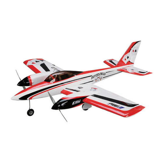
- Page 1 Deuces Wild ARF Assembly Manual Specifications Wingspan: 62 in (1570mm) Length: 62.5 in (1580mm) Wing Area: 740 sq in (47.7 sq dm) Weight w/o Battery: 9.2–10.5 lb (4.2–4.7 kg) Weight w/Battery: 7.75–8.5 lb (3.5–3.9 kg)
-
Page 2: Table Of Contents
Along with the Recommended Radio Equipment .......... 3 superior features that come with every E-flite Platinum Series Required Tools and Adhesives ..........4 plane, the Deuces Wild is full of enhanced details. All flight Notes Regarding Servos and ESC ........ -
Page 3: Contents Of Kit/Parts Layout
ST47 Standard Servo (6, 7 w/retracts) JSP98020 6-inch Y-Harness (3) EFLREX3L 3-inch Extension, Lightweight (4) EFLREX9L 9-inch Extension, Lightweight (2) EFLREX12L 12-inch Extension, Lightweight (2) The Spektrum trademark is used with permission of Bachmann Industries, Inc. E-flite Deuces Wild Assembly Manual... -
Page 4: Required Tools And Adhesives
60-Amp Pro Switch-Mode BEC Low-tack masking tape Mixing sticks Brushless ESC Paper towels Pin drill EFLB32003S (2 req) E-flite 3S 11.1V 3200mAh 20C Li-Po Rubbing alcohol Mixing cups APC12080E (1 req) 12x8 Electric Propeller Hobby knife (#11 blade) Pliers APC12080EP (1 req) -
Page 5: Note On Lithium Polymer Batteries
Keep loose items that can get entangled in the propeller away from the prop, including loose clothing, or other objects such as pencils and screwdrivers. Especially keep your hands away from the propeller. E-flite Deuces Wild Assembly Manual... - Page 6 3. Use a pin drill and 1/16-inch (1.5mm) drill bit to drill 5. Secure the elevator servo in the fuselage using the four holes for the servo mounting screws. the hardware provided with the servo and a #1 Phillips screwdriver. E-flite Deuces Wild Assembly Manual...
- Page 7 Never cut the receiver antenna as this will greatly reduce the range of your radio system. E-flite Deuces Wild Assembly Manual...
-
Page 8: Tail Attachment
You will thread this on until the end of the rod is flush with the nylon control horn. Note: If you are installing retracts, plug a 3-inch (76mm) extension into the port marked GEAR at this time as well. E-flite Deuces Wild Assembly Manual... - Page 9 Do not over-tighten the nuts and damage the fuselage. At this time the Rudder/Fin, Stab/Elevator, and Fuselage should fit tight against each other. 3. Slide the threaded rods into the holes in the rear of the fuselage. E-flite Deuces Wild Assembly Manual...
-
Page 10: Rudder And Elevator Linkage Installation
Make sure to slide a silicone clevis retainer onto the clevis before threading it onto the pushrod wire. 3. Use a pin drill and 5/64-inch (2mm) drill bit to enlarge the outer hole of the elevator servo horn. E-flite Deuces Wild Assembly Manual... - Page 11 Slide the servo horn onto the pushrod wire with the splined part of the horn that fits onto the servo toward the bend. 5. Use pliers to bend the pushrod wire 90 degrees at the mark made in the last step. E-flite Deuces Wild Assembly Manual...
- Page 12 Use a #1 Phillips servo horn. You may need to use pliers to apply enough screwdriver to reattach the servo horn to the elevator force to snap the pushrod keeper onto the wire. servo at the center position. E-flite Deuces Wild Assembly Manual...
- Page 13 12. Slide the wire into the rudder pushrod tube and connect the clevis to the rudder servo horn. Plug a Y-harness into the receiver rudder port of your receiver. The rudder and nose wheel steering servo will plug into this Y-harness. E-flite Deuces Wild Assembly Manual...
- Page 14 You will need to rotate the horn so it can be aligned with the pushrod for this step. Once the wire has been inserted, you can rotate the control horn so it is aligned with the pushrod wire. E-flite Deuces Wild Assembly Manual...
- Page 15 This is necessary may need to use pliers to apply enough force to snap the so the keeper doesn't bind against the fuselage during pushrod keeper onto the wire. the operation of the rudder. E-flite Deuces Wild Assembly Manual...
-
Page 16: Aileron Servo Installation
Drill bit: 1/16-inch (1.5mm), 5/64-inch (2mm) 1. Use sandpaper to roughen the ends of the four servo mounting blocks. Doing so will allow the epoxy applied to them in the next step a better surface to adhere to. E-flite Deuces Wild Assembly Manual... - Page 17 5. Apply 2–3 drops of thin CA into the holes to harden the surrounding wood. This provides a hard surface for the screws, making them more secure when installed. E-flite Deuces Wild Assembly Manual...
- Page 18 Once complete reinstall the servo horn using panel as shown. a #1 Phillips screwdriver. Use a pin drill and 5/64-inch (2mm) drill bit to enlarge to outer hole in the remaining servo arm as shown. E-flite Deuces Wild Assembly Manual...
- Page 19 With the aileron in the center position, use a felt-tipped pen to mark the pushrod where it crosses the hole in the Thread the clevis onto the 4 -inch (108mm) aileron aileron servo arm. pushrod wire. E-flite Deuces Wild Assembly Manual...
- Page 20 15. Slide the pushrod wire into the servo arm. 17. Repeat Steps 2 through 16 to install the remaining aileron servo and linkage. E-flite Deuces Wild Assembly Manual...
-
Page 21: Flap Servo Installation
3. Apply 2–3 drops of thin CA into each of the four holes. This will harden the surrounding wood to provide a hard surface for the screws to bite into so they will be more secure when installed. E-flite Deuces Wild Assembly Manual... - Page 22 7. Slide the brass pushrod connector in the hole drilled in rods until they are flush on top. Make sure they are the previous step. positioned equally or the flaps will not have the same amount of throw. E-flite Deuces Wild Assembly Manual...
- Page 23 You may need to use pliers to make a shown installed in the up flap position. slight bend in the linkage so it will not bind when the flaps are in operation. E-flite Deuces Wild Assembly Manual...
- Page 24 3mm x 5mm machine screw to secure the flap to these positions. linkage in the connector. Use threadlock on the screw to Flap Up: prevent it from vibrating loose. E-flite Deuces Wild Assembly Manual...
- Page 25 Half Flap: Full Flap: E-flite Deuces Wild Assembly Manual...
-
Page 26: Fixed Gear Installation
Note: Due to the model being designed for retracts and fixed gear, you might need to slightly sand the flashing off the edges of the fixed gear mounts to ensure an interference free fit in the wing. E-flite Deuces Wild Assembly Manual... - Page 27 3. Apply 2–3 drops of thin CA into each of the holes. landing gear. This will harden the surrounding wood and provide a harder surface for the screws, helping prevent them from pulling loose on a hard landing. E-flite Deuces Wild Assembly Manual...
- Page 28 7. Use a drill and 3/32-inch (2.5mm) drill bit to drill the wire. Make sure to slide a silicone clevis retainer onto the locations for the four screws. clevis before threading it onto the pushrod wire. E-flite Deuces Wild Assembly Manual...
- Page 29 13. Use a #1 Phillips screwdriver to remove the nose front of the fuselage. gear steering servo horn from the steering servo. Use a pin drill and 5/64-inch (2mm) drill bit to enlarge the outer hole of the steering servo horn. E-flite Deuces Wild Assembly Manual...
- Page 30 Use the rudder trim at the radio to correct for rudder trim in the air only. You may wish to trim the pushrod wire with side cutters once you have finalized the setting and nose wheel steering adjustment. E-flite Deuces Wild Assembly Manual...
-
Page 31: Retract Gear Installation
Your wires struts are pre-bent to the correct length and have been sized for the Deuces Wild. E-flite Deuces Wild Assembly Manual... - Page 32 6. Cut a 10-inch (254mm) piece of air line. Attach the 4. Use a drill and 3/32-inch (2.5mm) drill bit to drill the air line to the fitting on the nose gear retract. locations for the four screws. E-flite Deuces Wild Assembly Manual...
- Page 33 9. Secure the nose gear in the fuselage using a #2 Phillips screwdriver and four 3mm x 8mm self-tapping countersink screws. Note: You do not want any more than a 1/16-inch (1.5mm) gap between the crimp and the aft portion of the steering arm. E-flite Deuces Wild Assembly Manual...
- Page 34 12. Slide the two brass pushrod connectors in the holes drilled in the previous step. Note: The wheel is shown on the building surface for clarity and contrast. E-flite Deuces Wild Assembly Manual...
- Page 35 This will cause your nose gear to not lock down during extension. These should be a small amount of play in the steering cables (approximately 1 degree left and right on the nose wheel) to ensure correct operation. E-flite Deuces Wild Assembly Manual...
- Page 36 19. Cut a 3-inch (76mm) piece of air line and attach it to 17. Use a hobby knife to remove the covering from the fuselage to expose the pre-drilled hole for the air the air tank. fill fitting. E-flite Deuces Wild Assembly Manual...
- Page 37 3-inch (76mm) line coming from the T-fitting and air tank air line. Note: The air tank shown in the photos is not of the correct size. The correct size air tank is included with your retract package. E-flite Deuces Wild Assembly Manual...
- Page 38 This will harden the surrounding wood and provide a the wing. Use a pencil to transfer the locations for the harder surface for the screws, helping prevent them from mounting screws on to the landing gear rails. pulling loose. E-flite Deuces Wild Assembly Manual...
- Page 39 Use a drill and 3/16-inch (5mm) drill bit to enlarge the hole in the main wheel. 27. Secure the main gear in the wing center section using a #2 Phillips screwdriver and four 3mm x 8mm self- tapping countersink screws. E-flite Deuces Wild Assembly Manual...
-
Page 40: Retract Servo Installation
1. Use 6-minute epoxy to secure the retract servo tray in the wing as shown. Note: The wheel is shown on the building surface for clarity and contrast. 30. Repeat Steps 21 through 29 to install the remaining main gear retract. E-flite Deuces Wild Assembly Manual... - Page 41 4. Apply 2–3 drops of thin CA into each of the holes to harden the surrounding wood. This will provide a harder surface for the screws to bite into when installed. E-flite Deuces Wild Assembly Manual...
- Page 42 Attach a 3-inch (76mm) piece of air line to the T-fitting. Use either side cutters or scissors to cut the air 6. Attach the actuator valve to the plywood valve mount line. using the hardware provided with the valve. E-flite Deuces Wild Assembly Manual...
- Page 43 10. Connect a 6-inch piece of air line to the remaining fitting on the actuator valve. A female quick disconnect that mates to the male quick disconnect on the line coming from the air tank will need to be attached to this line. E-flite Deuces Wild Assembly Manual...
- Page 44 Install the servo horn on the retract servo. Note: You will need your transmitter and receiver for the next steps to set up your retract end points. E-flite Deuces Wild Assembly Manual...
- Page 45 Your retract servo should now be set way in between either side. Using threadlock, tighten the up and not binding. Trim the pushrod with side cutters machine screw and proceed to the next step. once you have the final adjustments complete. E-flite Deuces Wild Assembly Manual...
-
Page 46: Aileron And Throttle Servo Extensions
You may need to remove the servo horn and adjust it on the servo shaft at least once during the alignment process. Note: We used low-tack tape on each aileron extension lead to differentiate it from the throttle extension. E-flite Deuces Wild Assembly Manual... - Page 47 3. Use the string to pull the aileron and throttle aileron extensions. Repeat for the opposite side. extensions through the wing. The throttle extension will require routing through the opening above the wing tube as shown. E-flite Deuces Wild Assembly Manual...
-
Page 48: Power 25 Motor Installation
#2 Phillips screwdriver. Make sure to use threadlock on the screws to prevent them from vibrating loose. 3. Repeat Steps 1 and 2 to install the remaining motor. E-flite Deuces Wild Assembly Manual... -
Page 49: Power 32 Motor Installation
X-mount. The X-mount should sit on the back of the motor during this, providing you the ability to install each screw one at a time. E-flite Deuces Wild Assembly Manual... - Page 50 The motor will towards the firewall. be secured to the firewall using four 4-40 x 1-inch socket head screws and a 3/32-inch ball wrench in a later step. 3. Position the motor inside the nacelle. E-flite Deuces Wild Assembly Manual...
- Page 51 1-inch socket head screws that secure the X-mount to the firewall. Make sure to use threadlock to prevent the screws from vibrating loose. Hint: You may want to magnetize your Phillips screwdriver to hold the screw during this operation. E-flite Deuces Wild Assembly Manual...
-
Page 52: Propeller And Spinner Installation
The standard rotation propeller is installed on the left motor and the pusher propeller is installed on the right motor. Wing Right Wing Left E-flite Deuces Wild Assembly Manual... - Page 53 Note: It may be necessary to relieve the back opening in the spinner back plate to accept the E-flite prop collet. We use a rotary tool with a high speed bit to accomplish ...
- Page 54 Use low-tack tape to hold the nacelle in position while the epoxy cures. 6. Test fit the motor nacelles to the wing. The E-flite decal will face out toward the tip of the wing. E-flite Deuces Wild Assembly Manual...
- Page 55 Note: Use paper towels and rubbing alcohol to clean up 9. If using the E-flite 60 Amp ESC, you only need one any excess epoxy that squeezes out from the nacelles of the BEC's to be active. To disarm the BEC on one of onto the wing in this step.
-
Page 56: Wing Installation
1/4-20 x 2-inch nylon bolt (2) 4-40 x 1-inch socket head bolt (2) Required Tools and Adhesives Ball driver: 3/32-inch Flat screwdriver 1. Slide the wing tube into the socket in the wing center section. E-flite Deuces Wild Assembly Manual... -
Page 57: Canopy And Gear Door Installation
2-inch nylon bolts and a flat screwdriver to secure the wing to the fuselage. Ensure you connect the air lines as well as the servo wires from the wing into the respective ports on the receiver before fully installing the wing. E-flite Deuces Wild Assembly Manual... - Page 58 Drill the holes as close to the top and bottom of the cover from vibrating loose. as possible. 5. Repeat Steps 2 through 4 to install the remaining gear cover. E-flite Deuces Wild Assembly Manual...
-
Page 59: Center Of Gravity And Nose Cone Installation
The amount necessary may be small, and some configurations do not need weight at all. If you need nose weight, it is best to install it at the very far forward point of the nose cone. E-flite Deuces Wild Assembly Manual... -
Page 60: Control Throws
5/32-inch down Note: Measurements are taken at the widest point on the surface. These are general guidelines measured from our own flight tests. You can experiment with higher rates to match your preferred style of flying. E-flite Deuces Wild Assembly Manual... -
Page 61: Range Test Your Radio
Check all the control horns, servo horns, and clevises to make sure they are secure and in good condition. Replace any items that would be considered questionable. Failure of any of these components in flight would mean the loss of your aircraft. E-flite Deuces Wild Assembly Manual... -
Page 62: Flying Your Deuces Wild
Power up and steer the model straight. problem is. As the model approaches takeoff speed, pull back slightly on the We hope you enjoy flying your Deuces Wild ARF as much as elevator. Once you are airborne, retract the landing gear if you we do. -
Page 63: Safety, Precautions, And Warnings
Horizon. to all equipment not specifically designed and protected for Return of any goods by Purchaser must be approved in writing by this purpose. Horizon before shipment. E-flite Deuces Wild Assembly Manual... -
Page 64: Damage Limits
Provided warranty conditions have been met, your Product will be repaired or replaced free of charge. Repair or replacement decisions are at the sole discretion of Horizon Hobby. E-flite Deuces Wild Assembly Manual... -
Page 65: Instructions For Disposal Of Weee By Users In The European Union
CM187NS your local city office, your household waste disposal service or United Kingdom where you purchased the product. Horizon Technischer Service Otto-Hahn-Str. 9a 25337 Elmshorn Germany E-flite Deuces Wild Assembly Manual... -
Page 66: 2008 Official Ama National Model Aircraft Safety Code
Only personnel involved with flying the aircraft are allowed at or in front of the flight line. Intentional flying behind the flight line is prohibited. E-flite Deuces Wild Assembly Manual... - Page 67 E-flite Deuces Wild Assembly Manual...
- Page 68 © 2008 Horizon Hobby, Inc. 4105 Fieldstone Road Champaign, Illinois 61822 (877) 504-0233 horizonhobby.com E-fliteRC.com 13397...