Table of Contents
Advertisement
Quick Links
Advertisement
Table of Contents

Related Manuals for E-FLITE Super Airliner ARF


Summary of Contents for E-FLITE Super Airliner ARF
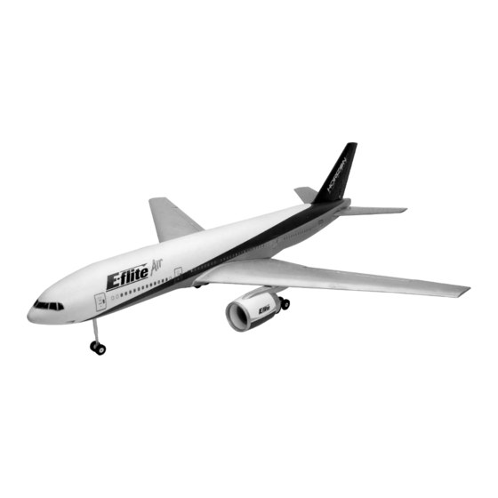
- Page 1 Super Airliner ARF Assembly Manual...
-
Page 2: Table Of Contents
Table of Contents Introduction............3 Questions.or.Assistance........6 Required.Radio.Equipment........3 Limited.Warranty.&.Limits.of.Liability.....7 Specifications.............4 Inspection.or.Repairs...........8 Outrunner.Motor.Setup........4 Warranty.Inspection.and.Repairs......8 Optional.Accessories...........4 Non-Warranty.Repairs.........8 Required.Tools.and.Adhesives.......4 Aileron.Servo.Installation........9 Contents.of.Kit/Parts.Layout........5 Motor.Installation..........13 Warning............5 Landing.Gear.Installation........18 Before.Starting.Assembly........5 Elevator.Servo.Installation........23 Note.on.Lithium.Polymer.Batteries......6 Rudder.Installation..........26 Using.the.Manual..........6 Final.Assembly..........29 Limited.Warranty.Period........6 Center.of.Gravity./.Battery.Installation....31 Safety.Precautions..........6 Control.Throws..........32 Questions,.Assistance,.and.Repairs.......6 Flying.the.Super.Airliner. -
Page 3: Introduction
We hope you enjoy your experience with this new offering E-flite bringing you, the modeler, the jet experience without from E-flite. So start building and set the date for your first the hassle of glow powered ducted fans or the cost of takeoff with E-flite Air! turbine engines. -
Page 4: Specifications
Specifications Required Tools and Adhesives Wingspan: 55 in (1400mm) Tools Length: 57 in (1450mm) Small Phillips Screwdriver Wing Area: 505 sq in (32.5 sq dm) (EFLA257 - included with EFLA250) Weight w/o Battery: 2.6 lb (1.2 kg) Hex Wrench: 1.5mm Weight w/Battery: 3.25 lb (1.5 kg) (EFLA251 - included with EFLA250) -
Page 5: Contents.of.kit/Parts.layout
Contents of Kit/Parts Layout Warning An RC aircraft is not a toy! If misused, it can cause serious Large Replacement Parts: bodily harm and damage to property. Fly only in open EFL7001 Wing w/Ailerons areas, preferably at AMA (Academy of Model Aeronautics) EFL7002 Fuselage w/Hatch &... -
Page 6: Note.on.lithium.polymer.batteries
Note on Lithium Polymer Batteries Safety Precautions Lithium Polymer batteries are significantly This is a sophisticated hobby product and not a toy. It must more volatile than alkaline or Ni-Cd/ be operated with caution and common sense and requires Ni-MH batteries used in RC applications. some basic mechanical ability. -
Page 7: Limited.warranty.&.Limits.of.liability
Limited Warranty & Limits of Liability Pursuant to this Limited Warranty, Horizon Hobby, Inc. will, REPAIR OR REPLACEMENT AS PROVIDED UNDER at its option, (i) repair or (ii) replace, any product determined THIS WARRANTY IS THE EXCLUSIVE REMEDY OF THE by Horizon Hobby, Inc. -
Page 8: Inspection.or.repairs
Inspection or Repairs Non-Warranty Repairs If your product needs to be inspected or repaired, please Should your repair not be covered by warranty and the call for a Return Merchandise Authorization (RMA). Pack expense exceeds 50% of the retail purchase cost, you will the product securely using a shipping carton. -
Page 9: Aileron.servo.installation
Aileron Servo Installation 1. Plug a 6" Y-harness into the receiver. Plug the two aileron servos into the Y-harness. Turn on the Required Parts radio system and center the trim and stick at the • Wing • 4 " (114mm) linkage w/clevis transmitter, ensure sub trims are at zero. - Page 10 Hint:.Use.threadlock.or.a.drop.of.thin.CA.on. 2. Enlarge the outer hole in the servo arm using the.nut.to.prevent.it.from.loosening.during.flight. a 5/64" (2mm) drill. 4. Mix a small drop of 6-minute epoxy and apply it onto the servo pocket. Press the servo into the pocket and allow the epoxy to cure before continuing to the next step.
- Page 11 5. Attach a 12" (305mm) extension to the servo 6. Apply the wiring decal over the servo wiring lead. Use a hobby knife to cut an opening at the from the engine pod over the servo. center of the wing.
- Page 12 8. Plug the servo extension into the Y-harness 9. Use side cutters to remove the excess pushrod and turn on the radio system. Center the aileron. wire so it will not interfere with the wing while the Use a 3mm setscrew to secure the pushrod wire in servo is moving.
-
Page 13: Motor.installation
Motor Installation 1. Route the motor wires through the pre-drilled holes in the fan housing. Required Parts • Wing • Motor (2) • Brushless speed control (2) • 2mm x 6mm screw (4) • Red wire, 25" (680mm) (2) •... - Page 14 2. Position the motor in the fan housing. Use 3. Slide the fan onto the motor shaft. Tighten the two 2mm x 6mm screws to secure the motor screw in the front of the fan using a flat blade to the fan housing.
- Page 15 4. Solder the appropriate connectors onto the 5. Route the lead and battery wires from the motor wires. Solder the 25" (680mm) wire for speed control through the opening made in the the battery onto the speed control and protect aileron servo installation.
- Page 16 6. Solder a connector to the battery wires that 7. Test fit the foam motor nacelle over the fan. matched your battery connector. Plug the speed Trim the foam using a hobby knife as necessary to control into the receiver.
- Page 17 8. Test fit the remaining foam nacelle to the 9. Tuck the wires neatly into the wire channels. fan. Use 30-minute epoxy to glue the foam fan Trim the foam if necessary to fit the connection nacelles to the fan and to the structure supporting between the servo and servo extension.
-
Page 18: Landing.gear.installation
Landing Gear Installation 11. Run the motors at full throttle and look for any rubbing of the fan blades to the outer shroud. Required Parts If any rubbing occurs, you can remove the fan • Wing • Fuselage rotor assembly and work the area with a rotary •... - Page 19 1. Loosen the setscrew in the main landing 2. Apply a small amount of threadlock onto gear assembly. Slide the gear onto the landing the setscrew. Tighten the setscrew onto the gear wire. Position the gear parallel to the wing landing gear wire.
- Page 20 4. Plug the steering servo into the rudder channel 5. Position the servo so the wheels are parallel to of the receiver. Center the trims and sub trim the plywood mounting plate. Use a pencil to mark on the radio and position the servo arm on the the location of the servo onto the plate.
- Page 21 6. Use medium CA to glue the two 1/2" x 3/8" x 7. Use the hardware provided with the servo to 3/8" (13mm x 9.5mm x 9.5mm) servo mounting attach it to the mounting blocks. blocks onto the mounting plate. Note:.The.mounting.blocks.must.be.on.the.
- Page 22 8. Turn the radio on and double-check that the 9. Attach a 12" servo extension to the steering wheels are parallel to the mounting plate. If not, servo. Slide the mounting plate into the fuselage. simply loosen the screw and setscrew so the Use a 2mm x 8mm sheet metal screw to secure wheels can be repositioned.
-
Page 23: Elevator.servo.installation
Elevator Servo Installation 1. Use hook and loop to attach the receiver inside the fuselage. Plug a 6" Y-harness into the rudder Required Parts channel of the receiver. Plug the steering servo • Fuselage • Pushrod connector assembly (2) into one lead from the Y-harness. - Page 24 2. Install the grommets and brass eyelets into the 3. Disconnect the clevises from the elevator horn elevator servo. Mount the elevator servo into the and pull the pushrod wires partially out of fuse, and then plug the servo into the receiver. the pushrod tubes.
- Page 25 4. Drill the outer hole in a servo arm using a 5/64" (2mm) drill bit. Attach the pushrod connector to the servo arm using a 2mm nut and threadlock. 6. Slide the elevator pushrod wires through the pushrod connector. Center the elevators and secure the wires using the 3mm setscrew.
-
Page 26: Rudder.installation
Rudder Installation Required Parts • Fuselage • Pushrod connector assembly (2) • Rudder w/fin • Servo Required Tools and Adhesives • Ruler • Drill • 6-minute epoxy • Drill bit: 5/64" (2mm) • 1.5mm hex wrench 7. Use medium CA to glue the pushrod tubes to the pushrod tube support. - Page 27 1. Position the rudder into the slot on the top of the 3. Enlarge the outer hole of the rudder servo arm fuselage. Measure from the tip of the rudder to using a 5/64" (2mm) drill bit. Attach the pushrod each stabilizer tip to make sure the measurements connector to the servo horn.
- Page 28 4. Slide the pushrod support onto the pushrod. Use 5. Slide the pushrod wire through the pushrod medium CA to glue the tube in position against connector. Center the rudder and rudder servo. the rear wing bolt plate and the servo tray. With Secure the wire using a 3mm setscrew.
-
Page 29: Final.assembly
Final Assembly 1. Remove the cover from the battery opening. Place the motor batteries into the fuselage. Use a piece Required Parts of hook and loop between the two batteries as • Fuselage • Wing well as between the battery and battery tray to •... - Page 30 2. Attach the wing to the fuselage using four 3mm x 3. Plug the speed controls into the batteries. Each 40mm screws and four 3mm washers. Remember battery will plug into its own individual speed to plug in the aileron and speed controls before control.
-
Page 31: Center.of.gravity./.Battery.installation
Center of Gravity / Battery Installation An important part of preparing the aircraft for flight is properly balancing the model. Caution: Do not inadvertently skip this step! The recommended Center of Gravity (CG) location for your Airliner is 5 " (140mm) back from the leading edge against the fuselage. -
Page 32: Control.throws
Control Throws The amount of control throw should be adjusted as closely as Note:.The.throws.listed.are.a.good.starting. possible using mechanical means, rather than making large point.for.most.flight.conditions. changes electronically at the radio. By moving the position Once the control throws have been set, slide the clevis of the clevis at the control horn toward the outermost hole, retainers onto the clevises to secure their positions. -
Page 33: Flying.the.super.airliner
Flying the Super Airliner during the flight. You will find you will need to use more stick With batteries charged and hooked up, check all control throw during basic and aerobatic flight than you will with a surfaces for correct throws and directions. Verify both propeller-driven model. -
Page 34: 2006 Official Ama National Model Aircraft Safety Code
2006 Official AMA National Model Aircraft Safety Code GENERAL 5) I will not fly my model unless it is identified with my name and address or AMA number on or in the 1) I will not fly my model aircraft in sanctioned events, model. -
Page 35: Official Ama National Model Aircraft Safety Code
2006 Official AMA National Model Aircraft Safety Code 4) I will operate my model using only radio control Documents of agreement and reports may exist frequencies currently allowed by the Federal between (1) two or more AMA Chartered Clubs, Communications Commission. (Only properly licensed (2) AMA clubs and individual AMA members not Amateurs are authorized to operate equipment on associated with AMA Clubs, or (3) two or more... - Page 36 © 2006 Horizon Hobby, Inc. 4105 Fieldstone Road Champaign, Illinois 61822 (877) 504-0233 www.horizonhobby.com www.E-fliteRC.com 8790...