Table of Contents
Advertisement
Quick Links
Advertisement
Chapters
Table of Contents

Related Manuals for E-FLITE Tensor 4D


Summary of Contents for E-FLITE Tensor 4D
- Page 1 Tensor 4D Assembly Manual...
-
Page 2: Table Of Contents
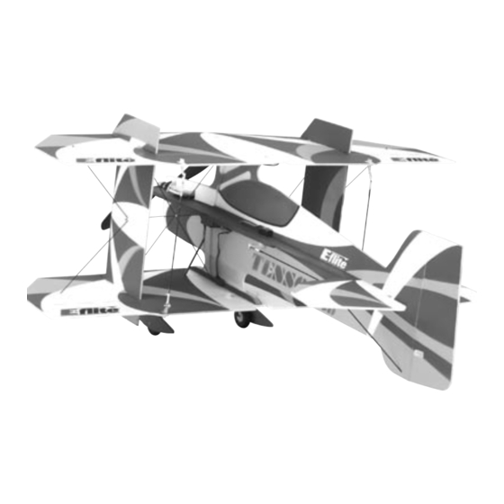
Table of Contents Introduction Introduction ............. 2 A true breakthrough in electric flight, the Tensor 4D Specifications ..........2 lightweight design takes extreme 3D aerobatics to a Warning ............3 new level. The Tensor is designed by Aerodynamicist Additional Required Equipment ......3 George Hicks, a top-level Unlimited Aerobatic ace. -
Page 3: Warning
Recommended JR® Systems Small Phillips screwdriver Servos: JR 241 Sub-micro servo (3) Motor/Gearbox Receiver: JR R610M 6-channel micro FM Rx or R610UL E-flite™ Park 370 Outrunner, 1080KV Radio: JR 4-channel system Propeller: 10x4.7 Battery and Speed Control Requirements Adhesives Li-Po Battery: 7.4V 860 2-Cell... -
Page 4: Contents Of Kit/Parts Layout
Contents of Kit/Parts Layout Large Replacement Parts: Small Replacement Parts: EFL2101 Wing Set w/Struts EFL2108 Carbon Fiber Wing Supports EFL2102 Vertical Fuselage w/Rudder EFL2109 Pushrods and Control Rods EFL2103 Horizontal Fuselage EFL2107 Nylon String (120") EFL2104 Tail Assembly EFLA200 Micro Control Horns EFL2105 Wheel Pants EFLA201... -
Page 5: Required Items
Required Items Before Starting Assembly Before beginning the assembly of your Tensor 4D, EFLP1047 10x4.7 Slow Flyer Propeller (2) remove each part from its bag for inspection. Closely JRP4487 Quattro UL, R610UL, 2-S241 JRPS241 S241 Sub-micro Servo inspect the fuselage, wing panels, rudder and EFLB1000 7.4v 860mAh 2-cell Li-Po, JST... -
Page 6: Warranty Information
Warranty Information Please note that once assembly of the model has been started, you must contact Horizon Hobby, Inc. Horizon Hobby, Inc. guarantees this kit to be free directly regarding any warranty question. Please from defects in both material and workmanship at the do not contact your local hobby shop regarding date of purchase. -
Page 7: Fuselage Assembly
Fuselage Assembly 2. Slide the horizontal fuselage partially into position. The unpainted side will face the bottom Required Parts of the fuselage. Vertical fuselage Horizontal fuselage Horizontal fuselage support (2) Elevator/stabilizer Carbon elevator joiner brace Required Tools and Adhesives Foam-safe CA Square ... - Page 8 3. Use foam-safe CA to attach the carbon 4. Slide the elevator/stabilizer assembly stabilizer joiner brace to the bottom of into position. the elevator.
- Page 9 5. Slide the horizontal fuselage fully forward in the 6. Use foam-safe CA to glue the horizontal fuselage. Center it in the main fuselage, making fuselage to the vertical fuselage. sure the notch at the rear fits with the stabilizer. Note: Do not use accelerator unless you are sure it will not harm the foam or paint on Note: There are small notches along the center...
- Page 10 7. Slide the stabilizer forward against the 8. Use foam-safe CA to glue the stabilizer horizontal fuselage. Use a square to check the into position. alignment to the fuselage. 9. Use foam-safe CA to glue the horizontal fuselage supports into position on the bottom of the fuselage support.
-
Page 11: Radio Installation
Radio Installation 1. Plug in the aileron, elevator and rudder servos to the receiver following the instructions from Required Parts your radio system. Turn on the radio and center Fuselage assembly the trims on the transmitter. Install long servo Micro control connector (2) arms on the servos. - Page 12 Note: The control horns can be modified 2. Attach the micro control horn to the elevator to greatly increase surface throws. Remove the using the micro control horn backplate. Place a back flange of the horn using scissors. Install few drops of foam-safe CA on the backplate to the horn by sliding the horn through the control ensure its security.
- Page 13 3. Install the rudder control horn, making sure it is 4. Trim one of the servo arms from the elevator on the opposite side of the elevator horn. servo. Cut a hole in the horizontal fuselage support to fit your servo. The servo must rest flush with the support.
- Page 14 5. Repeat Step 4 for the rudder servo. 6. Prepare one of the .065" x 16" carbon pushrods by attaching one of the 1/32" x 2" pushrod ends using 10" of string and thin CA. Make a 90-degree bend 1/4" from the end of the pushrod end.
- Page 15 7. Pass the bend in the pushrod through on of the 8. Tape the elevator so it will remain centered. holes in the elevator control horn. Use the outer Measure back 1/2" from the elevator servo arm hole for minimum throw and the inner hole for on the pushrod.
-
Page 16: Micro Pushrod Keeper
10. Install a micro control connector and 11. Attach the L-bend to the control horn using a connector backplate to the servo arm. micro pushrod keeper. - Page 17 12. Slide the pushrod end through the micro 13. Repeat Steps 7 through 13 to assemble and connector. Center the elevator and secure the install the rudder pushrod. pushrod using a 2mm x 4mm screw.
-
Page 18: Wing Installation
Wing Installation 2. Carefully check to make sure the lower wing is square to the fuselage. Use foam-safe CA to Required Parts glue the lower wing to the fuselage. Fuselage Assembly Lower wing Side force generator (2) Required Tools and Adhesives Foam-safe CA Hobby knife Square... - Page 19 3. Locate the side force generators. Use a sharp 4. Position the side force generator in the holes hobby knife to remove the upper and lower closest to the trailing edge of the bottom wing. fences from the main section. Use a square and foam-safe CA to glue the side force generator into position.
- Page 20 6. Place the top wing onto a flat surface. Position the side force generators and fuselage onto the wing. Hold the wing flat while gluing the fuselage and side force generators to the wing. Note: It is recommended to use a square to check the side force generator alignment to the top wing.
-
Page 21: Carbon Rod Installation
Carbon Rod Installation Required Parts Assembled airframe .046" x 11 ” carbon rod (4) .046" x 6 " carbon rod (6) Required Tools and Adhesives Foam-safe CA Thin CA T-Pin Note: You may want to locate a thin piece of depron or other foam for the next section. A thin board will work too. - Page 22 2. Slide a .046" x 11 " carbon rod from 3. Place the top wing on a surface that will allow the lower fuselage to the upper side force the wing panel to lie perfectly flat. Apply glue to generator.
- Page 23 5. Slide a .046" x 11 " carbon rod from 7. Repeat Steps 5 and 6 to complete the the upper fuselage to the lower side force cross bracing. generator. Leave at least 1/16" of the rod exposed at both ends. Glue only the rod at the fuselage.
- Page 24 8. Install one of the .046" x 6 " rods through 9. Use a straight edge to make sure the side the hole in the center of the side force generator force generator is not bent in or out on the and into the fuselage spine.
- Page 25 11. Locate two .046" x 6 " carbon rods for use 12. Cut a 10" piece of string. Wrap the string as the tip bracing. Glue the braces at the side around the junction of the inner braces. Use thin force generator first, and then check the wing CA to secure the string to the braces.
-
Page 26: Aileron Servo Installation
Aileron Servo Installation 1. Position the aileron servo on the bottom of the bottom wing so the output shaft is 4 " forward Required Parts of the trailing edge. Mark the position of the Assembled airframe front and rear of the servo onto the wing Micro control connector (4) using a T-pin. - Page 27 2. Cut a hole in the bottom wing and 3. Install the aileron servo using foam-safe CA. through the vertical fuselage that will fit your Make sure to glue the servo to both the wing particular servo. Make sure the hole is and the fuselage.
- Page 28 5. Build and install the linkages using two 6. Trim the remaining four control horns as shown. 1/32" x 3 " pushrods. Secure the linkages Enlarge the hole in two (2) of the control horns to the control horn using two micro pushrod using a 1/16"...
- Page 29 7. Install the remaining two micro connectors in 8. Install a horn from the previous step in the the drilled out horns. Make sure to install the upper wing. The connector will face outward, connectors opposite each other as shown. allowing access to the screw.
- Page 30 9. Install a control horn in the bottom aileron. 10. Assemble an aileron connecting pushrod using .065" x 7" carbon rod, 1/32" x 2" pushrod end and 10" of string. Bend the rod at a 90-degree angle and attach it to the bottom aileron control horn.
- Page 31 11. Cut the carbon at the rod at the mark made 12. Repeat Steps 8 through 11 to assemble in the previous step using a razor saw. Finish and install the remaining aileron connecting the assembly of the pushrod using a pushrod.
-
Page 32: Installing The Electronics
Installing the Electronics 2. Slide the motor into position in the fuselage. Glue the plywood mount to the fuselage using Required Parts foam-safe CA. Trim the fuselage as necessary to Assembled airframe Plywood motor mount clear the motor and wiring to the motor. 4-40 x 3/8"... - Page 33 3. Mount the receiver in an inconspicuous location 4. Solder any necessary connectors to your on the fuselage spine using hook and loop or speed control. Cut a small hole in the fuselage double-sided tape. Plug the elevator, rudder spine to pass the battery lead through.
- Page 34 5. Use hook and loop tape to secure the battery 6. Set up the operation of the motor using the directly to the side of the fuselage behind the instructions included with your particular speed motor positioned to obtain the correct CG. control at this time.
-
Page 35: Landing Gear Installation
Landing Gear Installation Note: Be very careful not to get CA onto the wheel, preventing it from rolling. Required Parts Assembled airframe Landing gear (2) 2. Slide the gear into position, but do not glue it " wheel (2) Wheel stopper (2) Wheel pant (2) yet. - Page 36 4. Position the wheels so they are parallel to the 5. Attach the wheel pants by gluing them to the fuselage centerline. Check to make sure the wheel stoppers. installation of the landing gear is not deforming the bottom wing. Use foam-safe CA to glue the landing gear to the wing, vertical fuselage and horizontal fuselage support.
-
Page 37: Final Assembly
Final Assembly 2. Repeat step 1 for the remaining carbon rod. Required Parts Assembled airframe 3. While the plane is upside down, install .065" x 6" carbon rod (2) the lower fences onto the bottom wing. Upper and lower side force generator (2) Required Tools and Adhesives Foam-safe CA ... -
Page 38: Control Throws
Control Throws 4. Turn the plane over so it is resting on its wheels. Install the upper fences using foam-safe CA. Aileron: 30 degrees Up 30 degrees Down (Use 40% expo) Elevator: 60 degrees Up 60 degrees Down (Use 60% expo) Rudder: 40 degrees Right 40 degrees Left... -
Page 39: Center Of Gravity
Center of Gravity General Set-up Tips for 3D Flight An important part of preparing the aircraft for People often spend a tremendous amount of time flight is properly balancing the model. constructing a perfectly straight airplane only to neglect the radio installation. The control system is Caution: Do not inadvertently skip this step! arguably of equal importance to actual construction and must be given adequate attention to ensure... - Page 40 flight is to hold the airplane vertically and advance This brings us to the most important aspect of 3D the throttle to full power. The static thrust should be setup—control surface deflection. Do you need enough to make the airplane accelerate vertically large amounts of deflection to hover? The truth from a standstill.
-
Page 41: Trimming And Flying The Tensor 4D
Trimming and Flying the Tensor 4D Large amounts of throw tend to make the airplane feel very sensitive around neutral. Because of this, Now that the airplane mechanical set-up is correct, it is highly recommended that you use a radio it is time to fine-tune the set-up in the air. - Page 42 an asymmetric vertical tail configuration, the Tensor Left and right rudder knife-edges will require has nearly equal vertical tail area above and below slightly different levels of mixing because of P- the thrustline. As a result the Tensor needs no side factor.
-
Page 43: Basic Guide For Learning To Fly 3D Maneuvers
Basic Guide for Learning to Fly 3D The Tensor is especially good at the 3D type maneuvers such as Torque Rolls, Elevators / Maneuvers Harriers, and High-Alpha Rolls. The large amount The Tensor is quite capable of performing a wide of aileron area in the propeller slipstream actually range of 3D maneuvers, but the ultimate goal is make it possible to perform anti-torque rolls... - Page 44 How much should you have to practice? If you are the more confidence you will have with the real serious about learning how to hover or torque roll, airplane and the nerves will eventually subside, work on the simulator 30 minutes to an hour each thus freeing your mind to concentrate on flying the night for a month.
- Page 45 Another common misnomer is that the ailerons do With this in mind let’s tackle the “Elevator” and not work while hovering. This could not be further “Harrier,” which is the second most popular 3D from the truth. If you do not use the ailerons during maneuver.
-
Page 46: 2004 Official Ama National Model Aircraft Safety Code
2004 Official AMA 5) I will not fly my model unless it is identified with my name and address or AMA number on or in the National Model Aircraft Safety Code model. (This does not apply to models while being flown indoors.) GENERAL 6) I will not operate models with metal-bladed... - Page 47 3) At all flying sites a straight or curved line(s) must 6) For Combat, distance between combat engagement be established in front of which all flying takes place line and spectator line will be 500 feet per cubic inch with the other side for spectators. Only personnel of engine displacement.
- Page 48 © 2004 Horizon Hobby, Inc. 4105 Fieldstone Road Champaign, Illinois 61822 (877) 504-0233 www.horizonhobby.com 7184...