Table of Contents
Advertisement
Available languages
Available languages
IT
MANUALE
TECNICO
Assistenza tecnica Italia
Commerciale Italia
Comelit Group S.p.A. - Via Don Arrigoni 5 - 24020 Rovetta S. Lorenzo BG Italy - tel. +39) 0346 750 011 - fax +39) 0346 71436
www.comelit.eu
www.simplehome.eu
EN
TECHNICAL
MANUAL
MT KIT 10
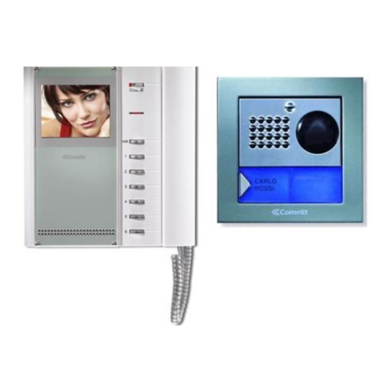
KIT VIDEO
BR VO KIT COLOR
COLOR BR VO KIT
COLOR BR VO KIT
Technical service abroad (+39) 0346750092
0346/750090
Export department
0346/750091
info@comelit.it
commerciale.italia@comelit.it
FR
MANUEL
TECHNIQUE
(+39) 0346750093
export.department@comelit.it
Advertisement
Chapters
Table of Contents

Related Manuals for Comelit COLOR BRAVO 8184


Summary of Contents for Comelit COLOR BRAVO 8184
- Page 1 Technical service abroad (+39) 0346750092 0346/750090 Commerciale Italia Export department 0346/750091 (+39) 0346750093 Comelit Group S.p.A. - Via Don Arrigoni 5 - 24020 Rovetta S. Lorenzo BG Italy - tel. +39) 0346 750 011 - fax +39) 0346 71436 www.comelit.eu www.simplehome.eu info@comelit.it commerciale.italia@comelit.it export.department@comelit.it...
- Page 2 • All the equipment must only be used for the purpose it was designed for. Comelit Group S.p.A. does not assume responsibility for improper use of the appliances, for modifications made by others for any reason or purpose, or for non-original accessories and materials.
- Page 3 MT KIT 1 KIT VIDEO BR VO KIT COLOR SOMMARIO SCHEMI DI COLLEGAMENTO • GENERALITÀ pag. • - BK/01C Schema base per kit monofamiliari Art. 8184 pag. 73 - BK/02BC Schema base per kit bifamiliari Art. 8185 POSTI ESTERNI • con collegamento in derivazione pag.
- Page 4 GROUP S P A GENERALITÀ Descrizione morsettiera LL connessione monitor (video, chiamata, fonica, apri porta) SE-SE connessione elettroserratura I Kit Video Citofonici Monofamiliare Art. 8184 e Bifamiliare ~ ~ alimentazione posto esterno Art. 8185 sono utilizzabili in edifici civili o terziari dove è richiesto PR morsetto di programmazione un’efficace controllo dell’accesso a fronte di semplici operazioni di - morsetto negativo da utilizzare in fase di programmazione...
- Page 5 MT KIT 1 Istruzioni di installazione Art. 4875KC, 4876KC • Murare la scatola a 160÷165 cm • Togliere il frontalino in acciaio dal pavimento finito, inox per eseguire le regolazioni in una zona agevole per la dei volumi e l’orientamento ripresa del visitatore.
- Page 6 GROUP S P A POSTI INTERNI 9. Pulsante disponibile di serie. 10. Pulsanti opzionali (utilizzando la scheda Art. 5733 o Art. 5734) per attivazione funzioni supplementari . Art. 5702 11. Pulsanti opzionali (utilizzando la scheda Art. 5733) o Led di segnalazione opzionali (utilizzando la scheda Art.
- Page 7 MT KIT 1 Installazione monitor Art. 5702 a parete Art. 5714KC DI P DI P cm 10,2 cm 11 cm 14,4 cm 1,4 cm 8,1 Staffa di fissaggio del monitor cm 1,4 La staffa di fissaggio Art. 5714KC consente l’installazione del Monitor a muro o tramite la base da tavolo Art.
- Page 8 GROUP S P A Procedura per togliere il Monitor Montaggio Monitor Art. 5702 sulla base da tavolo Art. 5712 Posizionamento etichetta sul monitor MT KIT 1...
- Page 9 MT KIT 1 Istruzioni di installazione Scheda opzionale Art. 5733, Art. 5734 D I P D IP 5734 5734 1 Estrarre la staffa e la scheda opzionale dalla propria confezione. 2 Avvitare la scheda opzionale con le apposite viti sul supporto plastico della staffa.
- Page 10 GROUP S P A Istruzioni per installazione citofono Style Art. 2608, 2628 e 2610 95mm 47,5mm 75,5mm 215mm Cover intercambiabile disponibile per gli Art. 2628 e Art. 2610 MT KIT 1...
- Page 11 MT KIT 1 Citofono Style Art. 2608 Citofono Basic con 2 pulsanti di serie. Non è utilizzabile per sfruttare la funzione intercomunicante. Il Citofono va montato sempre utilizzando l’Art. 1214/2C come mostrato nello schema di collegamento BK/DC a pagina 84. 1.
- Page 12 GROUP S P A Citofono Style Art. 2628 Citofono Elegance con funzioni e pulsanti supplementari. 11. Morsetti connessione impianto: L L connessione alla linea bus. Non è utilizzabile per sfruttare la funzione intercomunicante. CFP CFP ingresso chiamata da piano. Il Citofono va montato sempre utilizzando l’Art. 1214/2C come P3 C3 morsetti pulsante P3 C.
- Page 13 MT KIT 1 Citofono Style Art. 2610 Citofono Elegance con funzioni e pulsanti supplementari e 11. Morsetti connessione impianto: servizio intercomunicante. L L connessione alla linea bus. CFP CFP ingresso chiamata da piano. L’Art. 2610 ha la possibilità, (mediante apposito settaggio) di P2 C2 morsetti pulsante P2 C.
- Page 14 UTP5 Cat 5 (sez. 0,2 mm 150 m 40 m Ø 0,5 mm AWG 24)* (130 feet) (495 feet) Cavo Comelit Art. 4576 50 m 150 m e Art. 4578 (sez. 0,5 mm Ø 0,8 mm AWG 20)* (495 feet) (165 feet) * Nel caso si utilizzi un cavo multicoppiola usare una sola delle coppiole disponibili.
- Page 15 Cavo intrecciato e schermato (sez. 1 mm Ø 1,2 mm AWG 17) Cavo UTP5 cat 5 (sez. 0,2 mm Ø 0,5 mm AWG 24) Cavo Comelit Art. 4576 e Art. 4578 (sez. 0,5 mm Ø 0,8 mm AWG 20) MT KIT 1...
- Page 16 GROUP S P A IMPOSTAZIONI E DESCRIZIONE FUNZIONAMENTO SISTEMA BRAVO KIT Impostazioni staffa Art. 5714KC e citofoni Style Art. 2608, 2628 e 2610 La figura seguente mostra la posizione dei micro-interruttori e del Jumper JP1 della staffa 5714KC e dei micro-interruttori dei citofoni Style Art.
- Page 17 MT KIT 1 I valori di S1-1, S1-2, S1-3, S1-4 e S1-5 definiscono l’indirizzo di chiamata. Per la codifica sia delle staffe che dei citofoni fare riferimento alla seguente tabella. Tabella di programmazione dei Micro interruttori per codice utente su Staffe e citofoni Riferimento per Riferimento per intercomunicante...
- Page 18 GROUP S P A Il valore di S1-6, S1-7 e S1-8 (solo per staffa Art. 5714KC) definisce la modalità operativa in cui opererà il Sistema Bravo KIT come riportato nella seguente tabella. S1-6 S1-7 S1-8 Funzioni tasti Apriporta Pulsante Attuatore / Pulsante Libero Pulsante 1 Accensione interna / Richiesta Video Pulsante 2...
- Page 19 MT KIT 1 MICRO-INTERRUTTORI S1-1, S1-2, S1-3, S1-4 E S1-5 Anche senza sollevare la cornetta si ha la possibilità di visualizzare l’immagine trasmessa dal posto esterno, sempre premendo il Pulsante 2 - richiesta video. I valori dei micro-interruttori S1-1, S1-2, S1-3, S1-4 e S1-5 definiscono l’indirizzo di chiamata della staffa in oggetto nei Nella configurazione classica di BRAVO KIT, quindi, si possono confronti del posto esterno di chiamata.
- Page 20 GROUP S P A Per l'utilizzo e l'abilitazione del servizio vedi variante BK/PC a Gestione funzione Dottore La funzione Dottore permette pagina 89. In impianti dotati di due posti esterni, è possibile l’azionamento automatico dell’apriporta su chiamata all’indirizzo del visualizzare alternativamente l’immagine da un posto esterno o Videocitofono e/o Citofono dove la funzione è...
- Page 21 MT KIT 1 Impostazione citofono (opzionale) Art. 2610 Funzione Autoaccensione e Richiesta Video Funzione Autoaccensione (consigliata solo per impianti con 1 Nel caso si decida di ampliare il sistema BRAVO KIT con o 2 ingressi). L’ accensione del monitor avviene premendo e l’aggiunta di un Citofono opzionale Art.
- Page 22 GROUP S P A Programmazioni speciali Art. 4660KC Fig. 1 Fig. 2 Fig. 1A Fig. 2A Art. 3309 Fig. 3 Fig. 4 Sull’Art. 4660KC è possibile effettuare una serie di programmazioni 4. Attendere che venga emesso un tono di conferma avvenuta speciali in funzione delle varie esigenze di impianto.
- Page 23 MT KIT 1 ESPANDIBILITÀ DEL SISTEMA BRAVO KIT Negli schemi BK/EN/100C e BK/EN/101C a pag. 90, 92 riportati dell'Art. 4660C a bordo dell'Art. 4875KC o 4876KC come descritto nella sezione A di questo manuale viene mostrata una possibile nella seguente procedura e le staffe 5714KC con il codice configurazione d’impianto che offre la possibilità...
- Page 24 GROUP S P A DESCRIZIONE SCHEMI DI COLLEGAMENTO BRAVO KIT namento, fare riferimento alle indicazioni riportate a pagina 12. Configurazione Micro-interruttori (di seguito chiamati DIP) sulla staffa: DIP 1 su ON - DIP 2, DIP 3, DIP 4, DIP 5 su OFF: Schema base per kit monofamiliari Art.
- Page 25 MT KIT 1 DESCRIZIONE VARIANTI DI COLLEGAMENTO BRAVO KIT è possibile comandare il relè a bordo dell’attuatore tramite i pulsanti dedicati sul monitor e/o citofono. Portata relè attuatore: 10A. Per le modalità d’uso dell’Art. 1256 Utilizzo modulo telecamera scorporata Art. 1259C rifarsi al foglio tecnico FT SB2 02 dello stesso articolo.
-
Page 27: Table Of Contents
MT KIT 1 BR VO KIT COLOR VIDEO KIT SUMMARY CONNECTION DIAGRAMS • GENERAL INFORMATION page 26 • - BK/01C Main diagram for single-residence kits Art. 8184. page 73 - BK/02BC Main diagram for two-residence kits Art. 8185 EXTERNAL UNITS •... -
Page 28: General Information
GROUP S P A GENERAL INFORMATION Description of terminal block LL monitor connection (video, audio, audio, door lock release) SE-SE electric lock connection The Single-residence Video Door Entry Kits Art. 8184 and Two- ~ ~ external unit power supply residence Video Door Entry Kits Art. 8185 can be used in PR programming terminal residential or service sector buildings where effective access - negative terminal to be used in programming stage... -
Page 29: Installation Instructions Art. 4875Kc, 4876Kc
MT KIT 1 Installation instructions Art. 4875KC, 4876KC • Wall-mount the box 160÷165 cm • Remove the stainless steel front from the finished floor, to carry out volume adjustments in an area where it is easy to see and adjust the camera. the visitor. -
Page 30: Internal Units
GROUP S P A INTERNAL UNITS 11. Optional pushbuttons (using card Art. 5733) or optional signalling LEDs (using card Art. 5734) available for different functions as given on page 40. Art. 5702 12 Brightness control (turn clockwise to increase brightness). 13. -
Page 31: Wall-Mounting Of Monitor Art. 5702
MT KIT 1 Wall-mounting of monitor Art. 5702 Art. 5714KC DI P DI P cm 10,2 cm 11 cm 14,4 cm 1,4 cm 8,1 Monitor fixing bracket cm 1,4 The fixing bracket Art. 5714KC enables wall-mounting of the Monitor or installation by means of desk base Art. 5712 (for more information see page 29, 30). - Page 32 GROUP S P A Procedure for removing the Monitor Mounting Monitor Art. 5702 on desk base Art. 5712 Positioning of label on monitor MT KIT 1...
- Page 33 MT KIT 1 Optional card Art. 5733, Art. 5734 installation instructions D I P D IP 5734 5734 1 Remove the bracket and optional card from their package. 2 Secure the optional card on the plastic support of the bracket with the special screws.
- Page 34 GROUP S P A Style telephone Art. 2608, 2628 and 2610 installation instructions 95mm 47,5mm 75,5mm 215mm Interchangeable cover available for Art. 2628 and Art. 2610 MT KIT 1...
-
Page 35: Style Telephone Art. 2608
MT KIT 1 Style telephone Art. 2608 Basic telephone with 2 pushbuttons standard. Cannot be used for the intercom function. The Telephone must always be mounted using Art. 1214/2C as shown in the BK/DC connection diagram on page 84. 1. Door lock release pushbutton 2. -
Page 36: Style Telephone Art. 2628
GROUP S P A Style telephone Art. 2628 Elegance telephone with additional functions and 11. System connection terminals: pushbuttons. L L bus line connection. CFP CFP floor door call input. Cannot be used for the intercom function. P3 C3 terminals for pushbutton P3 C. NO. 24V 100mA The Telephone must always be installed using Art. -
Page 37: Style Telephone Art. 2610
MT KIT 1 Style telephone Art. 2610 Elegance telephone with additional functions and 11. System connection terminals: L L bus line connection. pushbuttons and intercom service. CFP CFP floor door call input. P2 C2 pushbutton P2 C terminals. NO. 24V 100mA dedicated By means of special setting, Art. -
Page 38: General Installation And Operation Instructions
UTP5 Cat. 5 150 m 40 m (section 0.2 mm Ø 0.5 mm AWG 24)* (495 feet) (130 feet) Comelit cable Art. 4576 150 m 50 m and Art. 4578 (section 0.5 mm Ø 0.8 mm (495 feet) (165 feet) AWG 20)* * In case of multipair cable, it is advisable to use only one of the pairs for the system. -
Page 39: Table Of Settings Art. 1216
Braided and screened cable (section 1 mm Ø 1.2 mm AWG 17) UTP5 cable cat. 5 (section 0.2 mm Ø 0.5 mm AWG 24) Comelit cable Art. 4576 and Art. 4578 (section 0.5 mm Ø 0.8 mm AWG 20) MT KIT 1... - Page 40 GROUP S P A BRAVO KIT SYSTEM SETTINGS AND DESCRIPTION OF OPERATION Settings of bracket Art. 5714KC and Style telephones Art. 2608, 2628 and 2610 The following figure shows the position of the microswitches and Jumper JP1 of bracket 5714KC and the microswitches of Style telephones Art.
-
Page 41: Setting Of Bracket Art. 5714Kc Main Or Secondary
MT KIT 1 The values of S1-1, S1-2, S1-3, S1-4 and S1-5 define the call address. Refer to the following table for the coding of brackets and telephones. Table of user code programming microswitches on Brackets and telephones Reference for Reference for intercom User code... - Page 42 GROUP S P A The value of S1-6, S1-7 and S1-8 (only for bracket Art. 5714KC) defines the mode in which the Bravo KIT System will operate as given in the following table. S1-6 S1-7 S1-8 Button functions Door lock release Pushbutton Actuator / Free Pushbutton Pushbutton 1...
- Page 43 MT KIT 1 MICROSWITCHES S1-1, S1-2, S1-3, S1-4 AND S1-5 without lifting the handset, simply by pressing Pushbutton 2 - video request. In the classic BRAVO KIT configuration, it is therefore possible to The values of the microswitches S1-1, S1-2, S1-3, S1-4 and S1-5 have at most 2 secondary Video doorphones and 1 main Video define the call address of the bracket in question with respect to the doorphone for each Call button, all powered by the same Art.
-
Page 44: Monitor Ringtone Selection Procedure
GROUP S P A On secondary Monitors, Pushbutton 2 also has the video request Monitor ringtone selection procedure function (for more information see page 43). The user can select the Monitor ringtone from a list of available ringtones, carrying out the following procedure: Switchboard call Press the Pushbutton set in this mode to send a call to the system porter Switchboard. -
Page 45: Setting Of Optional Telephone Art. 2610
MT KIT 1 Setting telephone (optional) Art. 2610 Video request and Automatic Switch-on function Automatic Switch-on function (recommended only for systems To extend the BRAVO KIT system by adding the optional with 1 or 2 entrances). Press and immediately release the Telephone Art. -
Page 46: Special Programming Art. 4660Kc
GROUP S P A Special programming Art. 4660KC Fig. 1 Fig. 2 Fig. 1A Fig. 2A Art. 3309 Fig. 3 Fig. 4 A number of special programming operations can be carried out on 4. Wait for a programming confirmation tone and remove the Art. -
Page 47: Bravo Kit System Expandability
MT KIT 1 BRAVO KIT SYSTEM EXPANDABILITY The diagrams BK/EN/100C and BK/EN/101C on page 90, 92, in of Art. 4660C on Art. 4875KC or 4876KC as described in the section A of this manual, show a possible system configuration following procedure, and the brackets 5714KC with the for managing up to a max. -
Page 48: A Second Art. 4876Kc, An Additional Secondary Monitor And
GROUP S P A DESCRIPTION OF BRAVO KIT CONNECTION DIAGRAMS the maximum operation distances. Configuration of microswitches (hereinafter DIP) on the bracket: DIP 1 ON - DIP 2, DIP 3, DIP 4, DIP 5 OFF: Basic wiring for single-family kits Art. 8184 set user code number 1 for call from two-residence external unit Diagram BK/01C Page 73... -
Page 49: Secondary Monitor With The Same User Code
MT KIT 1 DESCRIPTION OF BRAVO KIT CONNECTION VARIANTS Addition of actuator Art. 1256 Diagram BK/AC Page 86 Use of remote camera module Art. 1259C By connecting Art. 1256 in parallel to the terminals of bracket 5714KC the relay on the actuator can be controlled using the Diagram BK/05C Page 81 dedicated pushbuttons on the monitor and/or telephone. - Page 51 MT KIT 1 KIT VIDÉO BR VO KIT COLOR SOMMAIRE SCHÉMAS DE BRANCHEMENT • GÉNÉRALITÉS page 50 • - BK/01C Schéma base pour kit un appartement Art. 8184. page 73 - BK/02BC Schéma base pour kit deux appartements POSTES EXTÉRIEURS •...
-
Page 52: Généralités
GROUP S P A GÉNÉRALITÉS Description bornier LL connexion moniteur (vidéo, appel, phonie, ouvre-porte) SE-SE connexion électroserrure Les Kit Visiophoniques pour un appartement Art. 8184 et deux ~ ~ alimentation poste externe appartements Art. 8185 peuvent être utilisés dans des bâtiments PR borne de programmation privacys ou tertiaires dans lesquels un contrôle efficace de l’accès - borne négative à... -
Page 53: Instructions D'installation Art. 4875Kc, 4876Kc
MT KIT 1 Instructions d’installation Art. 4875KC, 4876KC • Murer le boîtier à 160÷165 cm • Enlever la façade en acier inox du sol fini, pour effectuer les réglages des dans une zone aisée pour voir le volumes et l’orientation de la visiteur. -
Page 54: Postes Intérieurs
GROUP S P A POSTES INTÉRIEURS CV4 comme indiqué dans la variante BK/PC page 89. 9. Bouton disponible de série. 10. Boutons en option (en utilisant la carte Art. 5733 ou Art. Art. 5702 5734) pour l’activation de fonctions supplémentaires. 11. -
Page 55: Installation Moniteur Art. 5702 Mural
MT KIT 1 Installation moniteur Art. 5702 mural Art. 5714KC DI P DI P cm 10,2 cm 11 cm 14,4 cm 1,4 cm 8,1 Bride de fixation du moniteur cm 1,4 Le bride de fixation Art. 5714KC permet d’installer le moniteur en saillie ou avec la base de table Art. - Page 56 GROUP S P A Procédure pour enlever le moniteur Installation moniteur Art. 5702 sur la base de table Art. 5712 Positionnement étiquette sur moniteur MT KIT 1...
-
Page 57: Instructions D'installation Carte En Option Art. 5733, Art. 5734
MT KIT 1 Instructions d’installation Carte option Art. 5733, Art. 5734 D I P D IP 5734 5734 1 Extrayez la bride et la carte en option de leurs emballages. 2 Vissez la carte option avec les vis spéciales sur le support plastique de la bride. -
Page 58: Instructions Pour Installation Combiné Parlophonique Style Art. 2608, 2628 Et 2610
GROUP S P A Instructions pour installation combiné parlophonique Style Art. 2608, 2628 et 2610 95mm 47,5mm 75,5mm 215mm Façade interchangeable disponible pour les Art. 2628 et Art. 2610 MT KIT 1... - Page 59 MT KIT 1 Combiné parlophonique Style Art. 2608 Combiné parlophonique Basic avec 2 boutons de série. Non utilisable pour la fonction intercommunicante. Le combiné parlophonique doit être monté en utilisant l’Art. 1214/2C comme l’indique le schéma de connexion BK/DC page 84. 1.
- Page 60 GROUP S P A Combiné parlophonique Style Art. 2628 Combiné parlophonique Elegance avec fonctions et boutons 11. Bornes pour le raccordement de l’installation : supplémentaires. L L connexion à la ligne bus. CFP CFP entrée de l’appel depuis l’étage. Non utilisable pour la fonction intercommunicante. P3 C3 bornes bouton P3 C.
- Page 61 MT KIT 1 Combiné parlophonique Style Art. 2610 Combiné parlophonique Elegance avec fonctions et boutons 11. Bornes pour le raccordement de l’installation : L L connexion à la ligne bus. supplémentaires et service intercommunicant. CFP CFP entrée de l’appel depuis l’étage. P2 C2 bornes bouton P2 C.
-
Page 62: Indications Générales D'installation Et Fonctionnement
UTP5 Cat 5 (sect. 0,2 mm 150 m 40 m Ø 0,5 mm AWG 24)* (495 feet) (130 feet) Câble Comelit Art. 4576 150 m 50 m et Art. 4578 (sect. 0,5 mm Ø 0,8 mm AWG 20)* (495 feet) (165 feet) * Lorsque l’on utilise un câble multipaires torsadées, on doit utiliser uniquement une paire torsadée disponible. - Page 63 Câble tressé et blindé (sect. 1 mm Ø 1,2 mm AWG 17) Câble UTP5 cat. 5 (sect. 0,2 mm Ø 0,5 mm AWG 24) Câble Comelit Art. 4576 et Art. 4578 (sect. 0,5 mm Ø 0,8 mm AWG 20) MT KIT 1...
-
Page 64: Programmations Et Description Fonctionnement Systeme Bravo Kit
GROUP S P A PROGRAMMATIONS ET DESCRIPTION FONCTIONNEMENT SYSTÈME BRAVO KIT Programmations bride Art. 5714KC et combinés parlophoniques Style Art. 2608, 2628 et 2610 La figure suivante montre la position des microswitches et du cavalier JP1 de la bride 5714KC et des microswitches des combinés parlophoniques Style Art. -
Page 65: Tableau De Programmation Microswitches Pour Code Usager Sur Brides Et Combinés Parlophoniques
MT KIT 1 Les valeurs de S1-1, S1-2, S1-3, S1-4 et S1-5 définissent l’adresse d’appel. Pour le codage des brides et des combinés parlophoniques, se référer au tableau suivant. Tableau de programmation des microswitches pour code usager sur brides et combinés parlophoniques Référence pour Référence pour intercommunicant... - Page 66 GROUP S P A La valeur de S1-6, S1-7 et S1-8 (uniquement pour bride Art. 5714KC) définit la modalité opérationnelle dans laquelle opère le système Bravo KIT, comme indiqué dans le tableau suivant. S1-6 S1-7 S1-8 Fonctions touches Ouvre-porte Bouton Actionneur / Bouton libre Bouton 1 Éclairage intérieur / Demande vidéo...
-
Page 67: Description Programmations Et Fonctions Boutons
MT KIT 1 MICROSWITCHES S1-1, S1-2, S1-3, S1-4 ET S1-5 À ce stade, le moniteur du visiophone principal s’éteint et l’image s’affiche au moniteur du visiophone sur lequel on a appuyé sur le Bouton 2 - Demande vidéo. Les valeurs des microswitches S1-1, S1-2, S1-3, S1-4 et S1-5 Même sans soulever le combiné, il est possible de visualiser définissent l’adresse d’appel de la bride en objet, par rapport à... - Page 68 GROUP S P A Auto-allumage / Demande Vidéo La pression du Bouton 2 L’activation de la communication avec l’unité extérieure interrompt la conversation interne en cours. dans cette modalité permet de visualiser sur l’écran du moniteur Un appel intercommunicant n’est pas prioritaire sur une l’image transmise depuis la plaque de rue même si aucun appel n’a conversation/un appel avec l’unité...
-
Page 69: Programmation Combiné Parlophonique Option Art. 2610
MT KIT 1 Programmation combiné parlophonique (option) Art. 2610 Fonction auto-allumage et demande vidéo Fonction Auto-allumage (conseillée uniquement pour les Si vous décidez d’augmenter le système BRAVO KIT en ajoutant installations avec 1 ou 2 entrées). un combiné parlophonique en option Art. 2610, veuillez trouver ci- Pour allumer le moniteur, appuyer sur le bouton 2 et le relâcher dessous le tableau nécessaire pour définir les fonctions que le immédiatement (si les programmations faites à... -
Page 70: Programmations Spéciales Art. 4660Kc
GROUP S P A Programmations spéciales Art. 4660KC Fig. 1 Fig. 2 Fig. 1A Fig. 2A Art. 3309 Fig. 3 Fig. 4 Sur l’Art. 4660KC, il est possible d’effectuer une série de avec I (Figure 3). programmations spéciales en fonction des différentes exigences 4. -
Page 71: Modularité Du Système Bravo Kit
MT KIT 1 MODULARITÉ DU SYSTÈME BRAVO KIT Les schémas BK/EN/100C et BK/EN/101C pages 90 et 92 boutons de l’Art. 4660C embarqué sur l’Art. 4875KC ou 4876KC contenus à la section A de ce manuel illustrent une configuration comme décrit dans la procédure suivante et les brides 5714KC avec d’installation possible, offrant la possibilité... -
Page 72: Connexion En Cascade
GROUP S P A DESCRIPTION SCHÉMAS DE CONNEXION BRAVO KIT fonctionnement, se référer aux indications page 60. Configuration microswitches (dénommés ci-après DIP) sur la bride : DIP 1 sur ON - DIP 2, DIP 3, DIP 4, DIP 5 sur OFF : Schéma base pour kit un appartement Art. -
Page 73: Connexion En Cascade
MT KIT 1 Schéma pour kit un appartement avec alimentateur face à la plaque de rue. Pour les modalités d’emploi de l’Art. 1256, voir la feuille technique FT SB2 02 de cet article. complémentaire Art. 1395. Schéma BK/01/AC page 80 Adjonction actionneur Art. - Page 74 GROUP S P A KIT VIDEO BRAVO-KIT COLOR BRAVO-KIT VIDEO KIT COLOR KIT VIDÉO BRAVO-KIT COLOR SCHEMI DI COLLEGAMENTO BK/01C • EN CONNECTION DIAGRAMS BK/02BC • SCHÉMAS DE BRANCHEMENT BK/02AC • BK/03BC • BK/03AC • BK/04BC • BK/04AC • BK/01/AC •...
- Page 75 (325 feet) UTP5 Cat 5 150 m 0,2 mm (Ø 0,5 mm - Ø 5/10 AWG 24) (495 feet) Comelit Art. 4576 / Art. 4578 150 m 0,5 mm (Ø 0,8 mm - Ø 8/10 AWG 20) (495 feet) 4875KC...
- Page 76 40 m 0,2 mm (Ø 0,5 mm - Ø 5/10 AWG 24) 4876KC (495 feet) (130 feet) Comelit Art. 4576 / Art. 4578 150 m 50 m 0,5 mm (Ø 0,8 mm - Ø 8/10 AWG 20) (495 feet) (165 feet)
- Page 77 (325 feet) UTP5 Cat 5 150 m 0,2 mm (Ø 0,5 mm - Ø 5/10 AWG 24) (495 feet) Comelit Art. 4576 / Art. 4578 150 m 4876KC 0,5 mm (Ø 0,8 mm - Ø 8/10 AWG 20) (495 feet)
- Page 78 GROUP S P A BK/03BC Schema per kit bifamiliari Art. 8185 ampliati con un secondo Art. 4876KC. Collegamento in derivazione. Wiring diagram for two-family kit Art. 8185 expanded with a second Art. 4876KC. Branched connection. Schéma pour kit deux appartements Art. 8185 avec un second Art. 4876KC. Connexion en dérivation. 4876KC 4876KC Pulsante comando apriporta locale...
- Page 79 MT KIT 1 BK/03AC Schema per kit bifamiliari Art. 8185 ampliati con un secondo Art. 4876KC. Collegamento in cascata. Basic wiring diagram for two-family kit Art. 8185 expanded with a second Art. 4876KC. Cascade connection. Schéma pour kit deux appartements Art. 8185 avec un second Art. 4876KC. Connexion en cascade. 4876KC 4876KC Pulsante comando apriporta locale...
- Page 80 GROUP S P A BK/04BC Schema per kit bifamiliari ampliati con un secondo Art. 4876KC, un ulteriore monitor secondario e un citofono per ciascuna unità familiare. Collegamento in derivazione. Wiring diagram for two-family kit expanded with a second Art. 4876KC, an additional secondary monitor and a telephone for each family unit.
- Page 81 MT KIT 1 BK/04AC Schema per kit bifamiliari ampliati con un secondo Art. 4876KC, un ulteriore monitor principale e un citofono per ciascuna unita familiare. Collegamento in cascata. Wiring diagram for two-family kit expanded with a second Art. 4876KC, an additional main monitor and a telephone for each family unit.
- Page 82 150 m 300 m 0,2 mm (Ø 0,5 mm - Ø 5/10 AWG 24) (495 feet) (990 feet) Comelit Art. 4576 / Art. 4578 150 m 300 m 0,5 mm (Ø 0,8 mm - Ø 8/10 AWG 20) (495 feet)
- Page 83 MT KIT 1 BK/05C Utilizzo modulo telecamera scorporata Art. 1259C. Use of remote camera module Art. 1259C. Utilisation module caméra déportée Art. 1259C. Da alimentare separatamente To be powered separately À alimenter séparément Per settaggio e funzionamento Art. 1259C vedi FT/SBC/05. For setting and operation Art.
-
Page 84: Sb2/Aar
GROUP S P A SB2/AAR Collegamento amplificatore video Art. 4833C. Connection of video amplifier Art. 4833C. Connexion amplificateur vidéo Art. 4833C. LINEA MONTANTE LINE RISER LIGNE MONTANT DAL POSTO ESTERNO FROM EXTERNAL UNIT DEPUIS LA PLAQUE DE RUE BK/HC Aggiunta di un monitor principale in parallelo, collegamento in cascata. Addition of main monitor in parallel connection in cascade. -
Page 85: Bk/Ic
MT KIT 1 BK/IC Aggiunta di un monitor principale in parallelo, collegamento in derivazione. Addition of a main monitor in parallel, with branched connection. Adjonction d un moniteur principal en parallèle. Connexion en dérivation. MONITOR PRINCIPALE MONITOR PRINCIPALE MAIN MONITOR MAIN MONITOR MONITEUR PRINCIPAL MONITEUR PRINCIPAL... -
Page 86: Bk/Dc
GROUP S P A BK/DC Aggiunta di un citofono in parallelo in derivazione dal montante. Addition of a parallel telephone. Branch connection from riser. Adjonction d un combiné parlophonique en parallèle en dérivation du montant. BKC/AAB Collegamento citofoni aggiuntivi in derivazione dal monitor. Connection of additional telephones, branch connection from monitor. -
Page 87: Bkc/Aaa
MT KIT 1 BKC/AAA Collegamento citofoni aggiuntivi in cascata dal monitor. Connection of additional telephones, connection in cascade from monitor. Connexion combinés parlophoniques supplémentaires en cascade du moniteur. BK/EC Aggiunta pilotaggio luce esterna tramite Art. 1256. Addition of external light control using of Art. 1256. Adjonction pilotage éclairage extérieur par Art. -
Page 88: Bk/Ac
GROUP S P A BK/AC Aggiunta attuatore Art. 1256. Addition of actuator Art. 1256. Adjonction actionneur Art. 1256. Per settaggio funzioni A,C,D,E dell'Art. 1256, vedi FT/SB2/02. For setting of functions A,C,D,E of Art. 1256, see FT/SB2/02. Pour programmation des fonctions A,C,D,E de l'Art. 1256, voir FT/SB2/02. -
Page 89: Bk/Oac
MT KIT 1 BK/OAC Variante utilizzo segnalazione PORTA APERTA. DOOR OPEN signalling use variant. Variante utilisation signalisation PORTE OUVERTE. Contatto N.C. per segnalazione PORTA APERTA (il led dei posti interni lampeggia). N.C. contact for DOOR OPEN signalling (the LED of the internal units flashes). Contact N.F. -
Page 90: Gen/Aab
GROUP S P A GEN/AAB Utilizzo Art. 1232 per filtraggio disturbi indotti sui morsetti S+ e S-. Use of Art. 1232 for filter induced interference on terminals S+ and S-. Utilisation Art. 1232 pour filtrage perturbations induites sur les bornes S+ et S-. VARIANTE B - VARIANT B Aggiunta pulsante di chiamata fuori porta. -
Page 91: Bk/Pc
MT KIT 1 BK/PC Utilizzo pulsante 1 per usi vari. Use of pushbutton 1 for various purposes. Emploi bouton 1 pour usages divers. 1205/B N.B. Le impostazioni di S1-6, S1-7 e S1-8 sono in funzione della configurazione desiderata (vedi tabella a pag 16). NOTE: The S1-6, S1-7 and S1-8 settings depend on the configuration required (see table on page 40). -
Page 92: Bk/En/100C
GROUP S P A BK/EN/100C Schema per connessione a porta principale di 3 BRAVO KIT tramite Art. 4834/9. Diagram for connecting 3 BRAVO KITS to main entrance panel by means of Art. 4834/9. Schéma pour connexion à porte principale de 3 BRAVO KIT avec l Art. 4834/9. Soluzione utilizzabile al massimo per 9 Bravo Kit. - Page 93 MT KIT 1 4875KC Pulsante comando apriporta locale Door-release button Bouton commande ouvre-porte local MT KIT 1...
-
Page 94: Bk/En/101C
GROUP S P A BK/EN/101C Schema di connessione a porta principale con centralino Art. 1998A (opzionale) di 30 BRAVO KIT (massimo). Derivazione Bravo Kit da 1214KC. Wiring diagram of a main door connection with porter switchboard Art. 1998A (optional) with 30 BRAVO KITS (maximum). Bravo Kit branch from 1214KC. Schema de connexion a la plaque de rue principale avec standard Art. - Page 95 MT KIT 1 4875KC 4875KC Pulsante comando apriporta locale Door-release button Bouton commande ouvre-porte local MT KIT 1...
- Page 96 Commerciale Italia Export department 0346/750091 (+39) 0346750093 [ B ] Comelit Group Belgium [ D ] Comelit Group Germany GmbH [ E ] Comelit Espana S.L. [ F ] Comelit Immotec Z.3 Doornveld 170 Brusseler Allee 23- 41812 Erkelenz Josef Estivill 67/69 - 08027 Barcelona...