MTD 500 series Shop Manual
Medium frame 2 & 3 stage
Hide thumbs
Also See for 500 series:
- Operator's manual (89 pages) ,
- Owner's manual (21 pages) ,
- Illustrated parts manual (12 pages)
Table of Contents
Advertisement
Quick Links
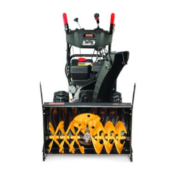
Medium Frame 2 & 3 Stage Snow Throwers
NOTE: These materials are for use by trained technicians who are experienced in the service and repair of outdoor power
equipment of the kind described in this publication, and are not intended for use by untrained or inexperienced individuals.
These materials are intended to provide supplemental information to assist the trained technician. Untrained or inexperi-
enced individuals should seek the assistance of an experienced and trained professional. Read, understand, and follow all
instructions and use common sense when working on power equipment. This includes the contents of the product's Oper-
ators Manual, supplied with the equipment. No liability can be accepted for any inaccuracies or omission in this publication,
although care has been taken to make it as complete and accurate as possible at the time of publication. However, due to
the variety of outdoor power equipment and continuing product changes that occur over time, updates will be made to these
instructions from time to time. Therefore, it may be necessary to obtain the latest materials before servicing or repairing a
product. The company reserves the right to make changes at any time to this publication without prior notice and without
incurring an obligation to make such changes to previously published versions. Instructions, photographs and illustrations
used in this publication are for reference use only and may not depict actual model and component parts.
MTD Products Inc. - Product Training and Education Department
Professional Shop Manual
(500, 600 and 700 series)
2005 to present
© Copyright 2013 MTD Products Inc. All Rights Reserved
Advertisement
Table of Contents

Related Manuals for MTD 500 series


Summary of Contents for MTD 500 series
- Page 1 Instructions, photographs and illustrations used in this publication are for reference use only and may not depict actual model and component parts. © Copyright 2013 MTD Products Inc. All Rights Reserved MTD Products Inc. - Product Training and Education Department...
-
Page 3: Table Of Contents
Auger Cable Adjustments (2-wheel Track Drives) ..........15 Speed Selector Cable ..................16 Speed Selector Rod ....................18 Auger and Drive Lever Interlock................20 Chapter 3: 500 Series Drive System Axle Assemblies ....................23 Hex Drive Shaft ....................26 Planetary Gears....................27 Friction Wheel Replacement ................29 Chapter 4: 600 Series Drive System Axle Assemblies ....................31... - Page 4 Chapter 6: 700 Series 3-Wheel Track-Drive System Track Removal/replacement ................53 Track Drive Assembly ..................58 Drive Axle Assemblies ..................59 Hex Drive Shaft and Planetary Gears ..............60 Friction Wheel Replacement ................63 Idler Hold Down Tools ..................64 Chapter 7: Auger Housing and Gear Box Skid Shoes ......................
-
Page 5: Chapter 1: Introduction
• Common sense in operation and safety is assumed. • In no event shall MTD or Cub Cadet be liable for poor text interpretation or poor execution of the proce- dures described in the text. • If the person using this manual is uncomfortable with any procedures they encounter, they should seek the help of a qualified technician or Cub Cadet Technical Support. - Page 6 Medium Frame 2 & 3 Stage Snow Throwers • Be prepared in case of emergency: ! CAUTION ! CAUTION Keep a fire extinguisher nearby Keep a first aid kit nearby Keep emergency contact numbers handy • Replace any missing or damaged safety labels on shop equipment. •...
-
Page 7: Fasteners
Identifying Snow Thrower Series NOTE: Medium frame two stage snow throwers are available as a 500, 600 or 700 series. 500 Series The 500 series features: • Steerable drive wheels • Auger housing width of 22” - 30” • 2 stage and 3 stage augers available. -
Page 8: Understanding Model And Serial Numbers
Medium Frame 2 & 3 Stage Snow Throwers 600 Series The 600 series features: • Solid drive wheel axles • Auger housing width of 22” - 30” • 2 stage augers Figure 1.2 700 Series The 700 series features: • Track drive (2 and 3 wheel versions) •... - Page 9 Introduction The model number is 31AH64FG795. The break down of what the model number means is as follows: • 31 - - - - - - - - - - - - - - - - - - - - - - - - Indicates that this is a snow thrower. •...
- Page 10 Medium Frame 2 & 3 Stage Snow Throwers...
-
Page 11: Chapter 2: Belts And Cables
Belts and Cables Chapter 2: Belts And Cables Auger Belt To remove/replace the Auger Belt: NOTE: Prior to servicing or replacing any belts stop the engine and allow it to cool. Then disconnect spark plug and ground it to the engine NOTE: If the unit is throwing the Auger Belt, inspect the round part of the Auger Housing that the impeller 3/8”... - Page 12 Medium Frame 2 & 3 Stage Snow Throwers Loosen the idler pulley enough for the belt to clear it using a 1/2” wrench. Slip the belt off of the engine pulley. Figure 2.3 Drain the fuel into an approved container. Carefully tip the snow thrower forward so it rests on the auger housing.
- Page 13 Belts and Cables NOTE: On 2005 through 2007 model years, the Return Spring hooked into a hole in the impeller housing. See Figure 2.6. NOTE: The idler bracket has a tab that acts as a brake, pressing against the Auger Belt whenever the Auger Control Lever is released.
-
Page 14: Drive Belt
Medium Frame 2 & 3 Stage Snow Throwers Drive Belt To remove/replace the drive belt: NOTE: Prior to servicing or replacing any belts, stop Torsion Drive the engine and allow it to cool. Then discon- Spring Idler Bracket nect spark plug and ground it to the engine Remove Auger Belt as described on the Auger Belt section of this chapter. -
Page 15: Auger Control Cable
Belts and Cables Auger Control Cable To remove/replace the Auger Control Cable: NOTE: The auger control is on the left side of the handle bars. Place an alignment mark on the adjustment bracket and the frame. See Figure 2.10. Loosen the hex screws securing the adjustment bracket to release tension off of the cable. - Page 16 Medium Frame 2 & 3 Stage Snow Throwers Detach the spring end of the cable from the Idler Pulley Bracket. See Figure 2.13. Install the cable by following the previous steps in reverse order. NOTE: When attaching he spring end of the cable, the open side of the spring faces the engine.
-
Page 17: Drive Clutch Control Cable
Belts and Cables Drive Clutch Control Cable To remove/replace the Drive Control Cable: NOTE: The drive control is on the right handle. Stop the engine and allow it to cool. Disconnect the spark plug wire and ground it to the engine. Drain the fuel into an approved container. -
Page 18: Auger And Drive Cable Adjustments (500, 600 And 3-Wheel Track Drives)
Medium Frame 2 & 3 Stage Snow Throwers Auger and Drive Cable Adjustments (500, 600 and 3-wheel Track Drives) NOTE: Prior to servicing or replacing any belts, stop the engine and allow it to cool. Then discon- nect spark plug and ground it to the engine Loosen the hex screws that secure the bracket that guides the cable needing adjustment using a 3/8”... -
Page 19: Auger Cable Adjustments (2-Wheel Track Drives)
Belts and Cables Auger Cable Adjustments (2-wheel Track Drives) Check the adjustment of the auger control: When the Auger Control Lever is released, in the disengaged or “up” position, the cable should have very little slack. It should not be tight. In a well-ventilated area, start the snow thrower engine. -
Page 20: Speed Selector Cable
Medium Frame 2 & 3 Stage Snow Throwers Speed Selector Cable To adjust the Speed Selector Cable: NOTE: Inspect the drive platter and friction wheel before adjusting the speed sector cable. Ensure that the friction wheel can freely travel through the whole range of positions. NOTE: A damaged or binding friction wheel can mimic a speed selector cable that is out of adjustment. - Page 21 Belts and Cables Loosen the cable screw and nut enough to free the z- fitting from the from the Speed Control Pivot Bracket. Screw See Figure 2.21. Figure 2.21 Remove the hair pin clip from the cable end. See Fig- ure 2.22.
-
Page 22: Speed Selector Rod
Medium Frame 2 & 3 Stage Snow Throwers Speed Selector Rod To adjust the Speed Selector Rod: NOTE: Inspect the drive platter and friction wheel before adjusting the Speed Selector Cable. Ensure that the friction wheel can freely travel trough the whole range of positions. NOTE: A damaged or binding friction wheel can mimic a speed selector cable that is out of adjustment. - Page 23 Slide the ball joint out of the Selector Assembly. Install the Selector Shaft by following the previous steps in reverse order. NOTE: The ball joint is a wear item. MTD recommends replacing the ball joint when installing the Speed Ball Joint Selector Shaft.
-
Page 24: Auger And Drive Lever Interlock
Medium Frame 2 & 3 Stage Snow Throwers Auger and Drive Lever Interlock To remove/service the Auger And Drive Lever Interlock: Loosen, but do not remove the two screws holding the auger cable using a 3/8” socket. See Figure 2.28. NOTE: Place an alignment mark on the adjustment bracket and the frame for reassembly. - Page 25 Belts and Cables NOTE: The pivot rod for early production models were nail headed. Current production models have a pow- ered medal end. See Figure 2.31. Nail headed Powdered metal end Figure 2.31 NOTE: The shoulder nuts are attached to the clutch lock Shoulder nut cams with a socket head screw.
- Page 26 Medium Frame 2 & 3 Stage Snow Throwers...
-
Page 27: Chapter 3: 500 Series Drive System
500 Series Drive System Chapter 3: 500 Series Drive System Axle Assemblies NOTE: Units with steerable drive wheels have a split axle Axle Shafts to allow each wheel to be driven independently of each other. See Figure 3.1. Axle Support Tube Figure 3.1... - Page 28 Medium Frame 2 & 3 Stage Snow Throwers Remove the wheels using a 1/2” wrench. NOTE: The ends of the axle shafts are a double-D. See Figure 3.3. Figure 3.3 Slide the spacers off of the axle. See Figure 3.4. Spacer Bushing Figure 3.4...
- Page 29 500 Series Drive System 56 tooth gear Slide one of the large 56T gears inward, while gently pulling the axle outward enough to expose the key that engages the gear. See Figure 3.6. Remove the key. 10. Hold the axle support tube and pull the shaft from the housing.
-
Page 30: Hex Drive Shaft
Medium Frame 2 & 3 Stage Snow Throwers Hex Drive Shaft To remove/replace a Hex Drive Shaft: Stop the engine and allow it to cool, disconnect the spark plug wire and ground it to the engine. Drain the fuel into an approved container. Carefully tip the snow thrower forward, so it rests on the auger housing opening. -
Page 31: Planetary Gears
500 Series Drive System Planetary Gears To inspect or repair the planetary gears. it is not nec- essary to completely remove the drive assembly from the snow thrower. Stop the engine and allow it to cool, disconnect the spark plug wire and ground it to the engine. - Page 32 Medium Frame 2 & 3 Stage Snow Throwers Inside of each planetary gear set is a series of plan- Sun Gear Planetary gears etary gears that rotate around a sun gear and rotate inside of the ring gear. See Figure 3.13. NOTE: The groves are grease grooves.
-
Page 33: Friction Wheel Replacement
500 Series Drive System Friction Wheel Replacement To remove/replace the Friction Wheel: Remove the Hex Drive Shaft by following the proce- dures described in the Hex Drive Shaft section of this chapter. Remove the bearing from one side of the Hex Drive Shaft. - Page 34 Medium Frame 2 & 3 Stage Snow Throwers...
-
Page 35: Axle Assemblies
600 Series Drive System Chapter 4: 600 Series Drive System Axle Assemblies With the engine stopped and allowed to cool, discon- nect the spark plug wire and ground it to the engine. Drain the fuel into an approved container. Carefully tip the snow thrower forward, so it rests on the auger housing opening. - Page 36 Medium Frame 2 & 3 Stage Snow Throwers Slide the spacers and washers off of the axle. See Figure 4.3. NOTE: There are usually 2 washers on the left side Spacer and only 1 on the right side. Bushing Washers Figure 4.3 Remove the E-rings from the axle shaft.
-
Page 37: Hex Drive Shaft Assembly
600 Series Drive System Hex Drive Shaft Assembly To remove/replace the Hex Drive Shaft Assembly: Remove the Axle Assembly as described in Axle Assemblies section of this chapter. Remove the E-ring from the left side of the drive shaft assembly. See Figure 4.6. Figure 4.6 Remove the bolt or nut, depending on production 9/16”... - Page 38 Medium Frame 2 & 3 Stage Snow Throwers Rotate the friction wheel assembly until the collar is free from the pin on the shift assembly. Maneuver the shaft partially through the wheel drive frame, then tilt the assembly forward to free it from the housing.
-
Page 39: Friction Wheel Replacement
600 Series Drive System Friction Wheel Replacement Remove the drive shaft by following the procedures described in the Hex Drive Shaft Assembly section of this chapter. Remove the bearing from one end of the shaft. Slide the Friction Wheel Assembly off of the shaft. NOTE: On the single speed models, drive out the roll pin holding the friction wheel to the hex shaft. - Page 40 Medium Frame 2 & 3 Stage Snow Throwers Inspect the parts for damage or wear. Install the rubber Friction Wheel by following the previous steps in reverse order. NOTE: Tighten the screws in a star pattern. See Figure 4.12. NOTE: The torque for the 1/4”-20 screws is 72 - 108 in lbs (8 - 12 Nm).
-
Page 41: Chapter 5: 700 Series 2-Wheel Track-Drive System
700 Series 2-Wheel Track-Drive System Chapter 5: 700 Series 2-Wheel Track-Drive System Track Adjustment To adjust track: Disconnect the spark plug wire from the spark plug Bottom of track and ground against engine. Note the direction Drain fuel from fuel tank. of the Track Tread NOTE: The tension on the tracks of the snow thrower can Pattern. -
Page 42: Track And Track Wheels
Medium Frame 2 & 3 Stage Snow Throwers Track and Track Wheels To remove/replace the Track and Track Wheels: Drive wheel NOTE: The Track and Track Wheels are removed and installed as one assembly. Disconnect spark plug wire from spark plug and ground it against the engine. -
Page 43: Hex Drive Shaft
700 Series 2-Wheel Track-Drive System Hex Drive Shaft To remove/replace the Hex Drive Shaft: Stop the engine and allow it to cool, disconnect the spark plug wire and ground it to the engine. Drain the fuel tank into an approved container. Carefully tip the snow thrower forward so it rests on the auger housing opening. - Page 44 Medium Frame 2 & 3 Stage Snow Throwers Remove the Patch Bolt and washer that secures the left Hex Drive Shaft Bearing. See Figure 5.8. Remove the bearing and spacer. Patch bolt Figure 5.8 Slide the Hex Drive Shaft out of the unit from the right side.
- Page 45 700 Series 2-Wheel Track-Drive System 12. Slide the Hex Drive Shaft into the frame from the right side, passing it through the Friction Wheel Assembly. NOTE: The side without the E-ring goes in first. Figure 5.11 13. Align the Hex Drive Shaft with the sprocket. 14.
- Page 46 Medium Frame 2 & 3 Stage Snow Throwers Install the bearing on the right side. See Figure 5.14. Install the Patch Bolt and washer. Place a small amount of 3-in-1, or similar oil, on a rag. Wipe a light coating of oil on the Hex Drive Shaft.
-
Page 47: Friction Wheel Replacement
700 Series 2-Wheel Track-Drive System Friction Wheel Replacement To remove/replace the Friction Wheel: Remove the Hex Drive Shaft by following the proce- dures described in the Hex Drive Shaft section of this chapter. Slide the Friction Wheel Assembly off of the pin on the Shift Arm. -
Page 48: Axle Shaft
Medium Frame 2 & 3 Stage Snow Throwers Axle Shaft To remove/replace an Axle Shaft: Remove the Track and Track Wheels of the affected axle by following the procedures described in the Track and Track Wheels section of this chapter. Remove the bottom access panel. - Page 49 700 Series 2-Wheel Track-Drive System 11. Drive out the old bushings using a drift punch. See Figure 5.21. Figure 5.21 12. Install new bushings in the axle tube. 13. Set the axle tube in place. 14. Slip the chain over the axle tube. 15.
-
Page 50: Planetary Gears And Shaft
Medium Frame 2 & 3 Stage Snow Throwers Planetary Gears and Shaft To remove/replace the planetary gears and shaft: Slip the chains off of both axles by following the pro- cedures described in the Axle Shaft section of this Triggers chapter. - Page 51 700 Series 2-Wheel Track-Drive System Slide the Planetary Shaft to the right enough for it to clear the transmission housing. See Figure 5.27. Slip the drive chain off of the sprocket on the end of the shaft. Figure 5.27 Remove the Planetary Shaft Assembly from the transmission box.
- Page 52 Medium Frame 2 & 3 Stage Snow Throwers Ring Gear Remove the Sun Gear. See Figure 5.30. Remove the Ring Gear and washer. Planetary Gears Sun Gear Figure 5.30 Remove the snap ring from the right Planetary Gear Set. See Figure 5.31. Remove the shim washers.
- Page 53 700 Series 2-Wheel Track-Drive System 23. Grease the needle bearing and the planetary gear posts on the carrier with Arctic Grease (737-0318- CRTG). See Figure 5.33. 24. Install the planetary gears on the carrier. NOTE: The grooves on the planetary gears are for grease. They are not timing marks.
- Page 54 Medium Frame 2 & 3 Stage Snow Throwers Measure the free travel of each Planetary Gear Set using a feeler gauge. NOTE: There should be 0.010” - 0.030” travel. NOTE: If there is too much travel, add a 0.020” shim, part number 936-0502. If there is not enough travel remove a shim.
-
Page 55: Steering Trigger Cables
700 Series 2-Wheel Track-Drive System Steering Trigger Cables To remove/replace a steering trigger cable: Disconnect the spark plug wire from spark plug and ground it against the engine. Drain the fuel tank into an approved container. E-ring Tip the snow thrower forward so that it rests on its auger housing opening. - Page 56 Medium Frame 2 & 3 Stage Snow Throwers Remove the bottom access panel. Remove the eight screws that hold the rear alumi- num housing in place, using a 1/2” wrench. See Fig- ure 3.40. Lift the housing out of the snow thrower. Figure 3.40 Squeeze the tabs on the end of the cable.
-
Page 57: Chapter 6: 700 Series 3-Wheel Track-Drive System
700 Series 3-Wheel Track-Drive System Chapter 6: 700 Series 3-Wheel Track-Drive System Track Removal/replacement To remove/replace the Tracks: NOTE: There is a spring loaded idler on both tracks, that will take up the slack in the Tracks as they stretch. Both of the spring loaded idlers need to be held down when doing any work or adjustments to the Tracks. - Page 58 Medium Frame 2 & 3 Stage Snow Throwers Remove the four screws that hold the bottom access panel in place using a 3/8” wrench. Slide the panel out from under the top of the frame. Rotate the panel until it is perpendicular to the frame and slide it out of the slot in the frame.
- Page 59 700 Series 3-Wheel Track-Drive System Rear Wheel 10. Slide the Rear Wheel off of the Rear Axle. See Figure 6.6. 11. Remove the Rear Wheel. 12. Lift the Track off of the machine. 13. Repeat on the opposite side. Figure 6.6 To install the tracks: Rear Axle If the Rear Axle fell out, set the it on the machine so...
- Page 60 Medium Frame 2 & 3 Stage Snow Throwers Place the Rear Wheel into its groove in the Track. Groove Slide the Rear Wheel onto the Rear Axle with the Track. See Figure 6.9. Install the retaining nut a couple of threads deep. IMPORTANT: Do not tighten the nut.
- Page 61 700 Series 3-Wheel Track-Drive System 11. Measure the Track tension: NOTE: Track tension must be checked with the Tracks off of the ground. 11a. Lay a straight edge across the section of Track between the Drive Wheel and the Rear Wheel. Pressure reading 11b.
-
Page 62: Track Drive Assembly
Medium Frame 2 & 3 Stage Snow Throwers Track Drive Assembly To remove/replace the Track Drive Assembly: Drive Wheel Remove the Tracks by following the procedures described in the Track removal/replacement section of this chapter. Remove the screw that secures the Drive Wheel to the drive axle using a 1/2”... -
Page 63: Drive Axle Assemblies
700 Series 3-Wheel Track-Drive System Drive Axle Assemblies To remove the Drive Axles: Remove the Tracks by following the procedures Split bushings described in the Track removal/replacement section of this chapter. Remove the Track Drive Assemblies by following the procedures described in the Track Drive Assemblies section of this chapter. -
Page 64: Hex Drive Shaft And Planetary Gears
Medium Frame 2 & 3 Stage Snow Throwers Hex Drive Shaft and Planetary Gears To remove the Hex Drive Shaft: Remove the Drive Axles by following the proce- dures described in the previous section of this chap- ter. Triggers Clamp down both Steering Triggers. See Figure 6.19. - Page 65 700 Series 3-Wheel Track-Drive System Thin Washer Thick Washer Remove the bearing and washers. NOTE: Keep track of the order of the washers for reas- sembly. See Figure 6.22. Bearing Figure 6.22 Carefully remove the E-ring that secures the Plane- tary Set.
- Page 66 Medium Frame 2 & 3 Stage Snow Throwers Inside of each Planetary Gear Set is a series of Planetary Gears Planetary Gears that rotate around a Sun Gear and rotate inside of the Ring Gear. See Figure 6.25. NOTE: The groves are grease grooves. Although the Planetary Gears rarely have any ser- vice issues, a good working knowledge is important.
-
Page 67: Friction Wheel Replacement
700 Series 3-Wheel Track-Drive System Friction Wheel Replacement To remove/replace the Friction Wheel: Remove the Hex Drive Shaft by following the proce- dures described in the Hex Drive Shaft section of this chapter. Remove the bearing and washers from one side of the Hex Drive Shaft. -
Page 68: Idler Hold Down Tools
Medium Frame 2 & 3 Stage Snow Throwers Idler Hold Down Tools Two tools are needed to hold down the spring loaded idlers. The components needed to assemble the tools are: • (2) forked angle brackets (50 x 55 mm). •... - Page 69 700 Series 3-Wheel Track-Drive System 50 mm 65 mm...
- Page 70 Medium Frame 2 & 3 Stage Snow Throwers...
-
Page 71: Chapter 7: Auger Housing And Gear Box
Auger Housing and Gear Box Chapter 7: Auger Housing and Gear Box NOTE: The Shave Plate and Skid Shoes on the bottom of the snow thrower are subject to wear. They should be checked periodically and replaced when necessary. Skid Shoes Reversible NOTE: There is a variety of Skid Shoes available for medium frame snow throwers. -
Page 72: Shave Plate
Medium Frame 2 & 3 Stage Snow Throwers Shave Plate To remove/replace the Shave Plate: Drain the fuel from the fuel tank. Tip the snow thrower back enough to access the shave plate. NOTE: Laying the snow thrower on its back will cause the engine cylinder to fill with oil. -
Page 73: Auger Housings
Auger Housing and Gear Box Auger Housings To remove/replace the Auger Housing: Disconnect and ground the spark plug wire. Remove the Discharge Chute by following the proce- dures described in appropriate discharge chute chap- ter. Remove the two screws that secure the belt cover 3/8”... - Page 74 Medium Frame 2 & 3 Stage Snow Throwers NOTE: On 2-Wheel Track units: • Remove the six nuts that hold the Auger Hous- ing to the transmission box using a 1/2” wrench. See Figure 7.8. Separate the Auger Housing from the transmission box.
-
Page 75: Auger Assemblies
Auger Housing and Gear Box Auger Assemblies To remove/replace the Auger Assembly: NOTE: The procedures for removing/replacing the Auger Assemblies are basically the same for a 2-stage and a 3-stage unit. Any differences will be covered when they arise. Separate the Auger Housing from the Transmission Box by following the procedures described in the Auger Housing section of this chapter. - Page 76 Medium Frame 2 & 3 Stage Snow Throwers Remove the screws holding the Bearing Housing on each side. See Figure 7.14. NOTE: This is a good opportunity to inspect the Auger Bearing for signs of wear. Figure 7.14 Pull the auger from the housing. Slight rotation of the assembly may be necessary to pull the Impeller Shaft clear of the rear bearing.
- Page 77 Auger Housing and Gear Box NOTE: 3-stage units have augers on the front and back of the Gear Box called Accelerators. See Figure 7.17. Pry off the front cap. 10. Remove the screw and washer from the end of the Input Shaft.
-
Page 78: 2-Stage Gear Boxes
Medium Frame 2 & 3 Stage Snow Throwers 2-Stage Gear Boxes To rebuild a 2-stage Gear Box: Remove the Gear Box by following the procedures Fill Plug described in the Auger Assemblies section of this chapter. Gently pry out the Fill Plug. See Figure 7.20. Turn the transmission over and drain any oil into an approved container. - Page 79 Auger Housing and Gear Box Remove the Input Shaft Assembly. Input Shaft Figure 7.23 Disassemble the Input Shaft Assembly. NOTE: The Input Shaft might be a little swollen at the dou- ble D, preventing the bushing and collar from slid- ing off.
- Page 80 Medium Frame 2 & 3 Stage Snow Throwers Remove the seals from the housings. Thoroughly clean the housings and remove all of the old sealant. Press new seals into the housings. See Figure 7.26. Seal Figure 7.26 Reassemble the Output Shaft, Worm Gear and washers.
- Page 81 Auger Housing and Gear Box 19. Apply 1.5 - 2 oz of 737-0168A grease to the gears and inside of the housing. See Figure 7.29. 20. Work the gears to distribute the grease between them. Figure 7.29 Thin bead of sealant 21.
-
Page 82: 3-Stage Gear Boxes
Medium Frame 2 & 3 Stage Snow Throwers 3-Stage Gear Boxes To rebuild a 3-stage Gear Box: Remove the Gear Box by following the procedures Cover described in the Auger Assemblies section of this chapter. Remove the four screws that secure the cover to the gear box housing using a 3/8”... - Page 83 Auger Housing and Gear Box Remove the rear Input Shaft (long side) Seal. Remove the snap ring. See Figure 7.34. Snap Ring Figure 7.34 10. Remove the Input Shaft from the rear of the Gear Box. 11. Lift the Worm Gear out of the Gear Box. See Figure 7.35.
- Page 84 Medium Frame 2 & 3 Stage Snow Throwers Drive out the front bearing.Figure 7.37. Remove the seal. Clean and dry all components. Inspect the components. NOTE: If there are signs of wear or damage, replace the affected component(s). Figure 7.37 Install the front bearing, using a brass punch to seat it.
- Page 85 Auger Housing and Gear Box 20. Set the Worm Gear inside the housing. See Figure 7.40. Figure 7.40 Short end 21. Insert the Input Shaft into the housing so that the short end rests in the front bearing. See Figure 7.41. 22.
- Page 86 Medium Frame 2 & 3 Stage Snow Throwers Insert the key into the Output Shaft. Insert the Output Shaft into the housing from the left side, passing it through the Worm Gear. See Figure 7.43. Rotate the Output Shaft until the key lines up with the slot in the Worm Gear.
-
Page 87: Chapter 8: Discharge Chute And Controls (Manual Crank)
Discharge Chute and Controls (Manual Crank) Chapter 8: Discharge Chute and Controls (Manual Crank) Remote Pitch Control Head (Plastic Chutes) To remove/replace the Remote Pitch Control Head: NOTE: The Remote Pitch Control Head consists of a Cable Guide, Cable Guide Bracket, and the cables that run to the pitch control lever/joystick. - Page 88 Medium Frame 2 & 3 Stage Snow Throwers Cable bracket Slide the Cable Guide out from in between the Cable Bracket and the Discharge Chute. See Figure 8.3. Disconnect the cables from the cable guide. Cable guide Figure 8.3 Mark one of the cables and its location in the Cable Bracket.
- Page 89 Discharge Chute and Controls (Manual Crank) Attach the cables to the Cable Guide. See Figure 8.6. Slide the Chute Deflector onto the Discharge Chute. NOTE: Do not apply grease to the inside surface of the Chute Deflector or the outside surface of the Dis- charge Chute.
-
Page 90: Remote Pitch Control Head (Steel Chutes)
Medium Frame 2 & 3 Stage Snow Throwers Remote Pitch Control Head (Steel Chutes) To remove/attach the Pitch Control Head to/from the Chute Deflector: NOTE: The Remote Pitch Control Head consists of a Cable Guide, Cable Guide Bracket, and the cables that run to the pitch control lever/ joystick. - Page 91 Discharge Chute and Controls (Manual Crank) Disconnect the cables from the Cable Guide. See Figure 8.10. Unhook the Cable Bracket from the Chute Deflector. Figure 8.10 To install the Chute Deflector: Hook the Cable Bracket onto the Chute Deflector. See Figure 8.11. Attach both cables to the Cable Guide.
- Page 92 Medium Frame 2 & 3 Stage Snow Throwers Set the Chute Wiper in place. Set the Chute Deflector on the chute. Wiper Figure 8.13 Align the deflector and the chute by inserting a car- riage bolt through the chute, wiper, deflector, Cable Guide and the Cable Bracket.
-
Page 93: Discharge Chute (Manual Crank, Cork Screw Style)
Discharge Chute and Controls (Manual Crank) Discharge Chute (Manual Crank, Cork Screw Style) To remove/replace the Discharge Chute: Pry open the three Flange Keepers securing the dis- charge chute to the chute adapter.Figure 8.15 Lift the chute assembly off the mounting base of the main housing. -
Page 94: Discharge Chute (With Remote Head)
Medium Frame 2 & 3 Stage Snow Throwers Discharge Chute (with Remote Head) Remove the hair pin clip that secures the shaft from the hand crank or joystick, if equipped. See Figure 8.16. Hair Pin Clip Figure 8.16 Remove the bow tie clip. Remove the clevis pin that holds the Remote Head Bow Tie Clip to the Support Bracket. - Page 95 Discharge Chute and Controls (Manual Crank) Remove the bolt that secures the Remote Head to the Discharge Chute. See Figure 8.19. Figure 8.19 The Discharge Chute will lift off of the Chute Collar. See Figure 8.20. Figure 8.20 Separate the Remote Head from the chute. See Fig- ure 8.21.
-
Page 96: Manual Crank, Cork Screw Style
Medium Frame 2 & 3 Stage Snow Throwers Manual Crank, Cork Screw Style To remove/replace the Chute Crank: Remove the flat washer and hair pin clip from the end of the Chute Crank. See Figure 8.22. Remove the wing nut from the eye bolt that attaches the crank to the handle. -
Page 97: Remote Head
Discharge Chute and Controls (Manual Crank) Remote Head To disassemble a manual crank Remote Head: NOTE: Procedures for rigid and flexible shaft Remote Heads are the same. Remove the hair pin clip that attaches the crank to the Remote Head. Slide the shaft out of the Remote Head. - Page 98 Medium Frame 2 & 3 Stage Snow Throwers Move the remote head to a workbench for service. Remove the four screws that hold the Gear Support to the cover using a 5/16” wrench. See Figure 8.27. Figure 8.27 Lift the Gear Set out of the Remote Head Cover. See Figure 8.28.
- Page 99 Discharge Chute and Controls (Manual Crank) 14. Insert a pick or similar tool into the hole in the Gear Shaft while removing the nut with a 9/16” wrench. See Figure 8.30. Figure 8.30 15. Remove the hex bushings, spring and washers from the shaft.
- Page 100 Medium Frame 2 & 3 Stage Snow Throwers Install the large holed washers and hex bushings onto the gear shaft. Install the small holed washers and the spring onto the Gear Shaft. Install the lock nut. Tighten it to a torque of 35 - 50 in lbs (4 - 6 Nm).
-
Page 101: Chapter 9: Discharge Chute And Controls (Joystick, Cable Style)
Discharge Chute and Controls (Joystick, Cable Style) Chapter 9: Discharge Chute and Controls (Joystick, Cable Style) Remote Pitch Control Head (Plastic Chutes) To remove/replace the Pitch Control Head: NOTE: The Remote Pitch Control Head consists of a Cable Guide, Cable Guide Bracket, and the cables that run to the pitch control lever/joystick. - Page 102 Medium Frame 2 & 3 Stage Snow Throwers Cable Bracket Slide the Cable Guide out from in between the Cable Bracket and the Discharge Chute. See Figure 9.3. Disconnect the cables from the Cable Guide. Cable Guide Figure 9.3 Unhook the cable assembly from the Chute Deflec- tor.
- Page 103 Discharge Chute and Controls (Joystick, Cable Style) Attach the cables to the Cable Guide. See Figure 9.6. Slide the Chute Deflector onto the Discharge Chute. NOTE: Do not apply grease to the inside surface of the Chute Deflector or the outside surface of the Dis- charge Chute.
-
Page 104: Discharge Chute (With Remote Head)
Medium Frame 2 & 3 Stage Snow Throwers Discharge Chute (with Remote Head) Remove the pitch control by following the proce- dures in the Remote Pitch Control Head section of this chapter. Remove the bow tie clip. Remove the clevis pin that holds the Remote Head to the Support Bracket. - Page 105 Discharge Chute and Controls (Joystick, Cable Style) Separate the Remote Head from the chute. See Fig- ure 9.10. Install the chute by following the previous steps in reverse order. NOTE: Some early production units with a remote head had Flange Keepers. If there were Flange Keepers on the discharge chute remove and discard them.
-
Page 106: Joystick (Cable Style)
Medium Frame 2 & 3 Stage Snow Throwers Joystick (Cable Style) To remove/replace the joystick: NOTE: The Remote Head and cables are part of the joystick and can not be serviced separately. NOTE: The procedures described here will cover the 2-way and the 4-way joystick. Bow Tie Remove the bow tie clip from the clevis pin that Clip... - Page 107 Discharge Chute and Controls (Joystick, Cable Style) Remove the six screws that fasten the joystick to the dash with a 3/8” wrench. See Figure 9.14. NOTE: Folding the handle bars down will allow easier access to the joystick assembly. Remove the joystick and its mounting bracket. Install the joystick by following the previous steps in reverse order.
- Page 108 Medium Frame 2 & 3 Stage Snow Throwers...
-
Page 109: Chapter 10: Discharge Chute And Controls (Joystick, Hex Shaft)
Discharge Chute and Controls (Joystick, Hex Shaft) Chapter 10: Discharge Chute and Controls (Joystick, Hex Shaft) Remote Pitch Control Head (Plastic Chutes) To remove/replace the Remote Pitch Control Head: NOTE: The Remote Pitch Control Head consists of a Cable Guide, Cable Guide Bracket, and the cables that run to the pitch control lever/joystick. - Page 110 Medium Frame 2 & 3 Stage Snow Throwers Cable Bracket Slide the Cable Guide out from in between the Cable Bracket and the Discharge Chute. See Figure 10.3. Disconnect the cables from the Cable Guide. Cable Guide Figure 10.3 Mark one of the cables and its location in the Cable Bracket.
- Page 111 Discharge Chute and Controls (Joystick, Hex Shaft) Attach the cables to the Cable Guide. See Figure 10.6. Slide the Chute Deflector onto the Discharge Chute. NOTE: Do not apply grease to the inside surface of the Chute Deflector or the outside surface of the Dis- charge Chute.
-
Page 112: Remote Head (Joystick, Hex Shaft)
Medium Frame 2 & 3 Stage Snow Throwers Remote Head (Joystick, Hex Shaft) To disassemble the Remote Head: Remove the two screws, indicated by the arrows in Figure 10.7, from the grip assembly using a #2 Phil- lips screwdriver. Slide the grip assembly off of the metal lever. Figure 10.7 Remove the final screw with the grip held in a hori- zontal position. - Page 113 Discharge Chute and Controls (Joystick, Hex Shaft) 11. Separate the Remote Head from the chute. See Fig- Separate here ure 10.10. Figure 10.10 NOTE: There is a flat washer between the Remote Head and the chute. If this washer is missing, the Flat washer Remote Head may bind up.
- Page 114 Medium Frame 2 & 3 Stage Snow Throwers Lift the Gear Support out of the cover enough to unhook the cable from the lock. See Figure 10.13. Remove the Gear Set from the cover Cable Figure 10.13 NOTE: If the cable or housing is to be replaced, dis- connect it from the Remote Head Housing.
- Page 115 Discharge Chute and Controls (Joystick, Hex Shaft) 17. Lift the Worm Gear Assembly out of the Gear Sup- port. 18. Slide the bushings washers and the Worm Gear off of the Gear Shaft. See Figure 10.16. Figure 10.16 19. Swing the Latch Pawl clockwise until there is enough clearance to remove the Pinion Gear Bushing.
- Page 116 Medium Frame 2 & 3 Stage Snow Throwers Slide the Worm Gear onto the Gear Shaft so that the alignment marks are facing and in-line with the holes in the Gear Shaft. See Figure 10.19. NOTE: If the worm gear is install backwards, the chute will not have full rotation.
- Page 117 Discharge Chute and Controls (Joystick, Hex Shaft) 28. Set the housing on top of the Gear Set. Install the four screws using a 5/16” wrench.Tighten the screws to a torque of 20 - 30 in lbs (2 - 3 Nm). See Figure 10.22.
-
Page 118: Joystick (Hex Shaft)
Medium Frame 2 & 3 Stage Snow Throwers Joystick (Hex Shaft) To disassemble a joystick: NOTE: The procedure to rebuild a 2-way and a 4- way joystick are very similar, any differences will be call out when necessary. Remove the two screws, indicated by the arrows in Figure 10.25, from the grip assembly using a #2 Phillips screwdriver. - Page 119 Discharge Chute and Controls (Joystick, Hex Shaft) NOTE: If working on a 2-way joystick, skip to step 11. 10. Remove the lock nut from the left side housing using a 1/2” wrench. See Figure 10.28. Lock nut Figure 10.28 11. Remove the eight screws that holds the housing assembly together using a #2 Phillips screwdriver.
- Page 120 Medium Frame 2 & 3 Stage Snow Throwers Lift the shaft and Sector Gear out of the housing. See Figure 10.31. Slide the Sector Gear and washers off of the shaft. The shaft can be separated by removing the roll pins.
- Page 121 Discharge Chute and Controls (Joystick, Hex Shaft) Pin the Pinion Gear to the Sector Gear with a 1/8” Arrow hex key, so that the arrow on the Pinion Gear is fac- ing the handle. See Figure 10.34. Handle Figure 10.34 Set the Pinion Gear, Sector Gear and shaft into the left housing with the hex key still in place.
- Page 122 Medium Frame 2 & 3 Stage Snow Throwers Set the right housing on top of the left housing. Hex key Install the eight screws. Slide the hex key out of the housing. See Figure 10.37. On 4-way units, install the lock nut and ground wire (if equipped) on the left side of the housing.
-
Page 123: Chapter 11: Discharge Chute And Controls (Electric)
Discharge Chute and Controls (Electric) Chapter 11: Discharge Chute and Controls (Electric) Remote Pitch Control Head (Plastic Chutes) To remove/replace the Remote Pitch Control Head: NOTE: The Remote Pitch Control Head consists of a Cable Guide, Cable Guide Bracket, and the cables that run to the Chute Control Assembly. - Page 124 Medium Frame 2 & 3 Stage Snow Throwers Cable Bracket Slide the Cable Guide out from in between the Cable Bracket and the Chute Deflector. See Figure 11.3. Disconnect the cables from the Cable Guide. Cable Guide Figure 11.3 Unhook the cable assembly from the Chute Deflec- tor.
- Page 125 Discharge Chute and Controls (Electric) Attach the cables to the Cable Guide. See Figure 11.6. Slide the Chute Deflector onto the Discharge Chute. NOTE: Do not apply grease to the inside surface of the Chute Deflector or the outside surface of the Dis- charge Chute.
-
Page 126: Remote Pitch Control Head (Steel Chutes)
Medium Frame 2 & 3 Stage Snow Throwers Remote Pitch Control Head (Steel Chutes) To remove/replace the Remote Pitch Control Head: NOTE: The Remote Pitch Control Head Consists of a Cable Guide, Cable Guide Bracket, and the cables that run to the Chute Control Assembly.. - Page 127 Discharge Chute and Controls (Electric) Disconnect the cables from the Cable Guide. See Figure 11.10. Unhook the Cable Bracket from the Chute Deflector. Figure 11.10 To install the Chute Deflector: Hook the Cable Bracket onto the Chute Deflector. See Figure 11.11. Attach both cables to the Cable Guide.
- Page 128 Medium Frame 2 & 3 Stage Snow Throwers Set the Chute Wiper in place. Set the Chute Deflector on the chute. Wiper Figure 11.13 Align the deflector and the chute by inserting a car- riage bolt through the cute, wiper, deflector, Cable Guide and the Cable Bracket.
-
Page 129: Discharge Chute
Discharge Chute and Controls (Electric) Discharge Chute Remove the hair pin clip that secures the shaft to the Remote Head. See Figure 11.15. Hair Pin Clip Figure 11.15 Remove the bow tie clip. Remove the clevis pin that holds the Remote Head to the Support Bracket. - Page 130 Medium Frame 2 & 3 Stage Snow Throwers Remove the bolt that secures the Remote Head to the Discharge Chute. See Figure 11.18. Figure 11.18 The Discharge Chute will lift off of the Chute Collar. See Figure 11.19. Figure 11.19 Separate the Remote Head from the chute.
- Page 131 Discharge Chute and Controls (Electric) Remote Head (Electric) Remove the Remote Head by follow the procedures described in the Discharge Chute section of this chapter. Move the Remote Head to a workbench for service. Remove the five screws that hold the Gear Support to the cover using a 5/16”...
- Page 132 Medium Frame 2 & 3 Stage Snow Throwers Remove the Pinion Gear Bushing. See Figure 11.24. Pinion Gear Bushing Figure 11.24 To reassembly the Remote Head: Slide the Worm Gear onto the Gear Shaft so that the alignment marks are facing and in-line with the holes in the Gear Shaft.
- Page 133 Discharge Chute and Controls (Electric) 3/4” 13. Insert the Pinion Gear so that the travel stop is 3/4” from the edge of the bracket. NOTE: Lubricate all friction surfaces with Renolit Polar Grease part number 937-04085. Figure 11.27 14. Set the housing on top of the Gear Set. Install the five screws using a 5/16”...
-
Page 134: Electric Chute Control
Medium Frame 2 & 3 Stage Snow Throwers Electric Chute Control Starting in 2012, an electric 4-way chute control sys- tem is available for some snow thrower models. There are two versions of the system: • Electric chute control with heated hand grips •... -
Page 135: Electric Joystick And Harness
Discharge Chute and Controls (Electric) Electric Joystick and Harness To remove/replace an electric joystick and harness: NOTE: The joystick is soldered into the harness. If the joy- stick needs to be replaced, the whole harness must be replaced. Ground lead Remove the screw that holds the harness ground lead to the engine using a 10 mm wrench. -
Page 136: Electric Joystick Bracket
Medium Frame 2 & 3 Stage Snow Throwers Remove the nut that is holding the joystick in place. See Figure 11.34. Gently remove the joystick from the Joystick Bracket. Install the joystick and harness by following the pre- vious step in reverse order. NOTE: Make sure the harness grommet is seated in the Joystick Bracket. - Page 137 Discharge Chute and Controls (Electric) Remove the right hand grip. NOTE: Unit without Heated Hand Grips can skip to step 7. 6a. Remove the two screws that hold the hand grip in place using a #2 Phillips screwdriver. See Figure 11.37. Slide the grip off of the handle.
- Page 138 Medium Frame 2 & 3 Stage Snow Throwers Loosen, but do not remove, the two screws that hold the control panel to the right handle bar. Figure 11.40 Shoulder Nut Shoulder Bolt While holding the Cam Lock’s shoulder nut with a 1/ 2”...
- Page 139 Discharge Chute and Controls (Electric) 13. Slip the Control Lever and Torsion Spring out of the machine. See Figure 11.43. Figure 11.43 14. Remove the two screws that are holding the Joystick Bracket to the handle bar with a #2 Phillips screw- driver.
-
Page 140: Chute Control Assembly
Medium Frame 2 & 3 Stage Snow Throwers Chute Control Assembly To remove/replace the Chute Control Assembly: Remove the hair pin clip that secures the shaft to the Remote Head. NOTE: The shaft has an offset so that it can be used to manually rotate the chute. -
Page 141: Chute Control Motors
Discharge Chute and Controls (Electric) Chute Control Motors To remove/replace a Chute Control Motor: Remove the Chute Control Assembly by following the procedures described in the previous section of this chapter. Remove the screws, indicated by the arrows in Fig- ure 11.48, using a #2 Phillips screwdriver. - Page 142 Medium Frame 2 & 3 Stage Snow Throwers Slide the coupler off of the motor. Figure 11.51 Remove the Chute Pitch Adapter. See Figure 11.52. NOTE: The pitch adapter may have fallen off when the housings where separated. Chute Pitch Adapter Figure 11.52 Turn the housing over.
- Page 143 Discharge Chute and Controls (Electric) Chute Pitch Adapter 11. Install the motors by following the previous steps in reverse order. NOTE: Make sure the Chute Pitch Adapter engages the Cable Guide as the housings are brought together. See Figure 11.54. NOTE: Tighten the screw that was removed in step 9 to a torque of 15 - 25 in lbs (2 - 3 Nm).
-
Page 144: Electric Chute Control Pitch Cables
Medium Frame 2 & 3 Stage Snow Throwers Electric Chute Control Pitch Cables To remove/replace the Pitch Cables: Remove the Chute Control Assembly by following the procedures described in the Chute Control Assembly section of this chapter. Remove the screws, indicated by the arrows in Fig- ure 11.56, using a #2 Phillips screwdriver. - Page 145 Discharge Chute and Controls (Electric) Cable Guide Disconnect the cables from the Cable Guide. See Figure 11.59. Figure 11.59 Squeeze in the barbs on the Cable Jacket End, while pulling the cable out of the housing. See Figure 11.60. Figure 11.60 Chute Pitch Adapter Install the cables by following the previous steps in reverse order.
- Page 146 Medium Frame 2 & 3 Stage Snow Throwers NOTE: Make sure the Rotation Motor Harness Grommet is seated in the notch in the hous- ings. NOTE: Make sure both motor harnesses are routed to the rear of the assembly as the housings are brought together.
-
Page 147: Schematics
Discharge Chute and Controls (Electric) Schematics Up, down, right and left refers to chute direction, which corresponds to back, forward, right and left respectively on the joystick. Electric chute control with heated hand grips Electric chute control without heated hand grips... - Page 148 Medium Frame 2 & 3 Stage Snow Throwers...
- Page 150 MTD Products Inc - Product Training and Education Department FORM NUMBER - 769-09302 09/2013...