Konica Minolta bizhub C30P Service Manual
Hide thumbs
Also See for bizhub C30P:
- Reference manual (292 pages) ,
- User manual (276 pages) ,
- System administrator manual (52 pages)
Table of Contents
Advertisement
Advertisement
Chapters
Table of Contents
Troubleshooting

Related Manuals for Konica Minolta bizhub C30P


Summary of Contents for Konica Minolta bizhub C30P
-
Page 1: Service Manual
SERVICE MANUAL FIELD SERVICE 2007.05 2007.05 Ver. 2.0 Ver. 2.0... -
Page 2: Table Of Contents
WARNING INDICATIONS ON THE MACHINE ............S-18 MEASURES TO TAKE IN CASE OF AN ACCIDENT ............S-21 Composition of the service manual ................. C-1 Notation of the service manual ..................C-2 bizhub C30P Main body General ........................... 1 Maintenance ........................5 Adjustment/Setting......................87 Troubleshooting...................... - Page 3 Blank Page...
-
Page 4: Safety And Important Warning Items
IMPORTANT NOTICE Because of possible hazards to an inexperienced person servicing this product as well as the risk of damage to the product, KONICA MINOLTA BUSINESS TECHNOLOGIES, INC. (hereafter called the KMBT) strongly recommends that all servicing be performed only by KMBT-trained service technicians. -
Page 5: Safety Warnings
[1] MODIFICATIONS NOT AUTHORIZED BY KONICA MINOLTA BUSINESS TECHNOLOGIES, INC. KONICA MINOLTA brand products are renowned for their high reliability. This reliability is achieved through high-quality design and a solid service network. Product design is a highly complicated and delicate process where numerous mechanical, physical, and electrical aspects have to be taken into consideration, with the aim of arriving at proper tolerances and safety factors. - Page 6 SAFETY AND IMPORTANT WARNING ITEMS [2] POWER PLUG SELECTION In some countries or areas, the power plug provided with the product may not fit wall outlet used in the area. In that case, it is obligation of customer engineer (hereafter called the CE) to attach appropriate power plug or power cord set in order to connect the product to the supply.
-
Page 7: Connection To Power Supply
SAFETY AND IMPORTANT WARNING ITEMS [3] CHECKPOINTS WHEN PERFORMING ON-SITE SERVICE KONICA MINOLTA brand products are extensively tested before shipping, to ensure that all applicable safety standards are met, in order to protect the customer and customer engi- neer (hereafter called the CE) from the risk of injury. However, in daily use, any electrical equipment may be subject to parts wear and eventual failure. - Page 8 SAFETY AND IMPORTANT WARNING ITEMS Power Plug and Cord WARNING • When using the power cord set (inlet type) that came with this product, make sure the connector is securely inserted in the inlet of the product. When securing measure is provided, secure the cord with the fixture properly.
- Page 9 SAFETY AND IMPORTANT WARNING ITEMS Wiring WARNING • Never use multi-plug adapters to plug multiple power cords in the same outlet. If used, the risk of fire exists. • When an extension cord is required, use a specified one. Current that can flow in the extension cord is limited, so using a too long extension cord may result in fire.
- Page 10 SAFETY AND IMPORTANT WARNING ITEMS Ventilation CAUTION • The product generates ozone gas during operation, but it will not be harmful to the human body. If a bad smell of ozone is present in the following cases, ventilate the room. a.
- Page 11 SAFETY AND IMPORTANT WARNING ITEMS Work Performed with the Product Powered On WARNING • Take every care when making adjustments or performing an operation check with the product powered. If you make adjustments or perform an operation check with the external cover detached, you may touch live or high-voltage parts or you may be caught in moving gears or the timing belt, leading to a risk of injury.
- Page 12 SAFETY AND IMPORTANT WARNING ITEMS Safety Checkpoints WARNING • Check electrode units such as a charging corona unit for deterioration and sign of leakage. Current can leak, leading to a risk of trouble or fire. • Before disassembling or adjusting the write unit (P/H unit) incorporating a laser, make sure that the power cord has been disconnected.
-
Page 13: Handling Of Consumables
SAFETY AND IMPORTANT WARNING ITEMS Safety Checkpoints WARNING • Make sure that all screws, components, wiring, connec- tors, etc. that were removed for safety check and mainte- nance have been reinstalled in the original location. (Pay special attention to forgotten connectors, pinched cables, forgotten screws, etc.) A risk of product trouble, electric shock, and fire exists. - Page 14 SAFETY AND IMPORTANT WARNING ITEMS Handling of Service Materials CAUTION • Use only a small amount of cleaner at a time and take care not to spill any liquid. If this happens, immediately wipe it off. A risk of fire exists. •...
- Page 15 SAFETY AND IMPORTANT WARNING ITEMS [4] Used Batteries Precautions ALL Areas CAUTION Danger of explosion if battery is incorrectly replaced. Replace only with the same or equivalent type recommended by the manufacturer. Dispose of used batteries according to the manufacturer’s instructions. Germany VORSICHT! Explosionsgefahr bei unsachgemäßem Austausch der Batterie.
-
Page 16: Internal Laser Radiation
SAFETY AND IMPORTANT WARNING ITEMS [5] Laser Safety • This is a digital machine certified as a Class 1 laser product. There is no possibility of danger from a laser, provided the machine is serviced according to the instruction in this manual. - Page 17 SAFETY AND IMPORTANT WARNING ITEMS U.S.A., Canada (CDRH Regulation) • This machine is certified as a Class 1 Laser product under Radiation Performance Stan- dard according to the Food, Drug and Cosmetic Act of 1990. Compliance is mandatory for Laser products marketed in the United States and is reported to the Center for Devices and Radiological Health (CDRH) of the U.S.
- Page 18 SAFETY AND IMPORTANT WARNING ITEMS Finland, Sweden LUOKAN 1 LASERLAITE KLASS 1 LASER APPARAT VAROITUS! • Laitteen käyttäminen muulla kuin tässä käyttöohjeessa mainitulla tavalla saat- taa altistaa käyttäjän turvallisuusluokan 1 ylittävälle näkymättömälle laser- säteilylle. puolijohdelaser Laserdiodin suurin teho 15 mW aallonpituus 770-800 nm VARNING!
-
Page 19: Laser Safety Label
SAFETY AND IMPORTANT WARNING ITEMS Laser Safety Label • A laser safety label is attached to the inside of the machine as shown below. A011P0E504DA Laser Caution Label • A laser caution label is attached to the outside of the machine as shown below. A011P0C503DA S-16... -
Page 20: Precautions For Handling The Laser Equipment
SAFETY AND IMPORTANT WARNING ITEMS PRECAUTIONS FOR HANDLING THE LASER EQUIPMENT • When laser protective goggles are to be used, select ones with a lens conforming to the above specifications. • When a disassembly job needs to be performed in the laser beam path, such as when working around the printerhead and PC Drum, be sure first to turn the printer OFF. -
Page 21: Warning Indications On The Machine
SAFETY AND IMPORTANT WARNING ITEMS WARNING INDICATIONS ON THE MACHINE Caution labels shown are attached in some areas on/in the machine. When accessing these areas for maintenance, repair, or adjustment, special care should be taken to avoid burns and electric shock. High voltage •... - Page 22 SAFETY AND IMPORTANT WARNING ITEMS High voltage • This area generates high voltage. Be careful not to touch here when the power is turned ON to avoid getting an elec- tric shock. High voltage • This area generates high voltage. Be careful not to touch here when the power is turned ON to avoid getting an elec-...
- Page 23 SAFETY AND IMPORTANT WARNING ITEMS WARNING • Do not burn used Print Units. Toner expelled from the fire is dangerous. WARNING • Do not burn used Waste Toner Bottle. Toner expelled from the fire is dangerous. WARNING • Do not burn used Toner Cartridge. Toner expelled from the fire is dangerous.
-
Page 24: Measures To Take In Case Of An Accident
MEASURES TO TAKE IN CASE OF AN ACCIDENT MEASURES TO TAKE IN CASE OF AN ACCIDENT 1. If an accident has occurred, the distributor who has been notified first must immediately take emergency measures to provide relief to affected persons and to prevent further damage. - Page 25 MEASURES TO TAKE IN CASE OF AN ACCIDENT Blank Page S-22...
-
Page 26: Composition Of The Service Manual
Composition of the service manual This service manual consists of Theory of Operation section and Field Service section to explain the main machine and its corresponding options. Theory of Operation section gives, as information for the CE to get a full understanding of the product, a rough outline of the object and role of each function, the relationship between the electrical system and the mechanical system, and the timing of operation of each part. -
Page 27: Notation Of The Service Manual
Notation of the service manual A. Product name In this manual, each of the products is described as follows: (1) bizhub C30P Main body (2) Microsoft Windows 95: Windows 95 Microsoft Windows 98: Windows 98 Microsoft Windows Me: Windows Me Microsoft Windows NT 4.0:... - Page 28 SERVICE MANUAL FIELD SERVICE Main body 2007.05 Ver. 2.0...
- Page 29 Revision history After publication of this service manual, the parts and mechanism may be subject to change for improvement of their performance. Therefore, the descriptions given in this service manual may not coincide with the actual machine. When any change has been made to the descriptions in the service manual, a revised version will be issued with a revision mark added as required.
- Page 30 Field Service Ver. 2.0 May 2007 CONTENTS bizhub C30P Main body General System configuration....................1 Product specifications ..................... 2 Maintenance Periodical check ...................... 5 Maintenance items....................5 3.1.1 Parts to be replaced by users (CRU) ............5 3.1.2 Parts to be replaced by a service engineer (FRU) ........6 Maintenance parts ....................
- Page 31 Field Service Ver. 2.0 May 2007 Disassembly/adjustment-prohibited items ............38 Disassembly/assembly/cleaning list (other parts) ..........39 6.2.1 Disassembly/assembly parts list..............39 6.2.2 Cleaning parts list ..................40 Disassembly/assembly procedure..............41 6.3.1 Front door ....................41 6.3.2 Upper front cover ..................41 6.3.3 Right front cover..................
- Page 32 Field Service Ver. 2.0 May 2007 6.3.34 Media feed clutch /2 (CL3) ................79 6.3.35 Temperature/ humidity sensor (TEM/HUMS) ..........82 6.3.36 IDC sensor board /Re, IDC sensor board /Fr (IDCSB/R, IDCSB/L) .... 83 Cleaning procedure .................... 84 6.4.1 Tray 1 feed roller..................84 6.4.2 Tray 2 feed roller..................
- Page 33 Field Service Ver. 2.0 May 2007 9.4.6 JOB SEPARATION ................... 121 9.4.7 IMAGE ROTATION..................121 QUALITY MENU....................122 9.5.1 COLOR MODE ..................122 9.5.2 BRIGHTNESS ..................122 9.5.3 HALFTONE....................122 9.5.4 EDGE ENHANCEMENT................123 9.5.5 EDGE STRENGTH................... 123 9.5.6 ECONOMY PRINT ................... 124 9.5.7 GLOSSY MODE ..................
- Page 34 Field Service Ver. 2.0 May 2007 9.9.11 LCD CONTRAST ..................145 9.9.12 SECURITY....................145 9.9.13 CLOCK...................... 146 9.9.14 HDD FORMAT ..................147 9.9.15 CARD FORMAT ..................147 9.9.16 RESTORE DEFAULTS ................148 9.9.17 ENABLE WARNING.................. 154 9.10 MAINTENANCE MENU ..................156 9.10.1 How to enter the MAINTENANCE MENU ..........
- Page 35 Field Service Ver. 2.0 May 2007 13.4.4 Misfeed at transfer section................ 179 13.4.5 Misfeed at fusing/exit section..............180 13.4.6 Media misfeed in control logic..............181 Malfunction code....................182 14.1 Trouble codes (service call) ................182 14.1.1 Trouble code list ..................182 14.2 Resetting a malfunction..................
- Page 36 Field Service Ver. 2.0 May 2007 14.3.31 C015: BOOT ROM error at startup ............195 14.3.32 C025: Controller ROM error (Configuration information error)....195 14.3.33 C026: Controller ROM error (Access error) ..........195 14.3.34 C027: Controller ROM error (Data error) ..........195 14.3.35 C050: HDD access error ................
- Page 37 Field Service Ver. 2.0 May 2007 Appendix Parts layout drawing.................... 219 17.1 Main body......................219 17.2 Lower feeder unit (option)................. 222 17.3 Duplex option (option) ..................223 17.4 Staple finisher (option) ..................224 Connector layout drawing ................... 227 Timing chart ......................228 viii...
-
Page 38: General
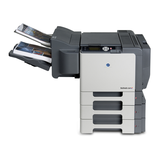
Field Service Ver. 2.0 May 2007 1. System configuration General System configuration System front view A011F1C501DA Main body Lower feeder unit Duplex option Lower feeder unit Hard disk kit Staple finisher... -
Page 39: Product Specifications
2. Product specifications Field Service Ver. 2.0 May 2007 Product specifications A. Type Type Desktop tandem full-color laser beam printer Printing system Semiconductor laser and electrostatic image transfer to media Exposure system 4 laser diode and polygon mirror PC drum type OPC (organic photo conductor) Photoconductor Blade cleaning system... - Page 40 Field Service Ver. 2.0 May 2007 2. Product specifications Media types Tray 1 • Plain paper (60 to 90 g/m / 16 to 24 lb) • Recycled paper (60 to 90 g/m / 16 to 24 lb) • Thick stock 1 (91 to 150 g/m / 24 to 40 lb) •...
- Page 41 2. Product specifications Field Service Ver. 2.0 May 2007 D. Machine specifications Power requirements AC 110 to 127 V, -10 % +6 % (AC 120 V -10 % +10 %: only US/Canada) Voltage: AC 220 to 240 V, -10 % +10 % Frequency: 50 to 60 Hz ±...
-
Page 42: Maintenance
Field Service Ver. 2.0 May 2007 3. Periodical check Maintenance Periodical check Maintenance items 3.1.1 Parts to be replaced by users (CRU) Class Part to be replaced Number of prints Clean Replace Description High-capacity toner 12,000 (MP **) cartridge *(C,M,Y,K) Processing Print unit (C,M,Y,K) 30,000 (MP **) -
Page 43: Parts To Be Replaced By A Service Engineer (Fru)
3. Periodical check Field Service Ver. 2.0 May 2007 3.1.2 Parts to be replaced by a service engineer (FRU) Class Part to be replaced Number of prints Clean Replace Description 150,000 (MP *) Fusing Fusing unit section 130,000 (2P/J Tray 2 media feed Feed roller 300,000... -
Page 44: Concept Of Parts Life
Field Service Ver. 2.0 May 2007 3. Periodical check Concept of parts life Description Near life value Life value • Detected by the waste toner full Monochrome Monochrome sensor. : 32,000 prints : 36,000 prints • A waste toner full condition is detected when about 4,000* mono- Waste toner chrome printed pages are pro-... -
Page 45: Maintenance Procedure (Periodical Check Parts)
3. Periodical check Field Service Ver. 2.0 May 2007 Maintenance Procedure (periodical check parts) 3.4.1 Replacing the tray 2 feed roller A. Periodically replace parts/cycle • Tray 2 feed roller: Every 300,000 prints B. Procedure 1. Slide out Tray 2. 2. -
Page 46: Replacing The Tray 1 Feed Roller
Field Service Ver. 2.0 May 2007 3. Periodical check 3.4.2 Replacing the tray 1 feed roller A. Periodically replace parts/cycle • Tray 1 feed roller: Every 300,000 prints B. Procedure 1. Open the tray 1. 2. Remove the tray 1 cover. 3. - Page 47 3. Periodical check Field Service Ver. 2.0 May 2007 NOTE Make sure that the bearing goes all the way into both of [1] shown on the left when installing the feed roller cover. A011F2C502DA 7. Remove the two screws [1]. 8.
-
Page 48: Replacing The Ozone Filter
Field Service Ver. 2.0 May 2007 3. Periodical check 10. Snap off the C-clip [1] and then remove the clutch [2] and the feed roller [3]. A011F2C552DA NOTE • When reinstalling the feed roller [1] and the clutch, make sure that it is mounted in the direction shown in the illustration on the left. -
Page 49: Replacing The Toner Cartridge (C/M/Y/K)
3. Periodical check Field Service Ver. 2.0 May 2007 3.4.4 Replacing the toner cartridge (C/M/Y/K) A. Periodically replace parts/cycle • High-capacity toner cartridge (C/M/Y/K): Every 12,000 prints B. Removal procedure 1. Open the front door. 2. Slide the lock lever [1] to the right. A011F2C505DA 3. - Page 50 Field Service Ver. 2.0 May 2007 3. Periodical check C. Reinstallation procedure 1. Take the toner cartridge out of its plastic bag. 2. Gently shake the toner cartridge [1] three times to agitate the toner. A011F2C508DA 3. Grasp the toner cartridge handle [1] and slide the toner cartridge [2] in.
-
Page 51: Replacing The Print Unit (C,M,Y,K)
3. Periodical check Field Service Ver. 2.0 May 2007 5. Raise the lock lever [1]. A011F2C511DA 6. Slide the lock lever [1] to the left to lock the toner cartridge. 7. Close the front door. A011F2C512DA NOTE • When removing or reinstalling the toner cartridge while it is being used or after it has been used up, do not hold it or place it upside down, as spilled toner could result. - Page 52 Field Service Ver. 2.0 May 2007 3. Periodical check 3. Pull down the lock lever [1] to unlock the print unit. A011F2C514DA 4. Press down the “Push” marked place [1]. 5. Pull the print unit [2] out. A011F2C515DB C. Reinstallation procedure 1.
- Page 53 3. Periodical check Field Service Ver. 2.0 May 2007 2. Remove the shipping tape from the print unit [1]. A011F2C517DA 3. Remove the protective cover [1]. A011F2C518DB 4. Slide the print unit [1] in. A011F2C519DA...
- Page 54 Field Service Ver. 2.0 May 2007 3. Periodical check 5. Raise the lock lever [1]. A011F2C520DA 6. Slide the lock lever [1] to the left to lock the print unit. 7. Close the front door. A011F2C521DA NOTE • When installing and removing the print unit, take care not to touch the surface of the PC drum [1].
-
Page 55: Replacing The Waste Toner Bottle
3. Periodical check Field Service Ver. 2.0 May 2007 3.4.6 Replacing the waste toner bottle A. Periodically replace parts/cycle • Waste toner bottle: Every 36,000 prints (when printed in black only) Every 9,000 prints (when printed in black only) B. Procedure 1. -
Page 56: Replacing The Transfer Roller
Field Service Ver. 2.0 May 2007 3. Periodical check 3.4.7 Replacing the transfer roller A. Periodically replace parts/cycle • Transfer roller: Every 120,000 prints B. Procedure 1. Open the right door. 2. Press the locks [2] located at the front and rear ends of the transfer roller [1] inward to unlock the transfer roller [1]. -
Page 57: Replacing The Transfer Belt
3. Periodical check Field Service Ver. 2.0 May 2007 3.4.8 Replacing the transfer belt A. Periodically replace parts/cycle • Transfer belt: Every 120,000 prints B. Procedure 1. Turn OFF the power switch. 2. Open the front door. 3. Remove the print unit (C,M,Y,K). See P.14 4. - Page 58 Field Service Ver. 2.0 May 2007 3. Periodical check 9. Grasp the transfer belt handle and pull the transfer belt out. A011F2C530DA 10. Remove the packing material from the new transfer belt. NOTE • Use care not to touch the belt of the transfer belt.
-
Page 59: Replacing The Fusing Unit
3. Periodical check Field Service Ver. 2.0 May 2007 3.4.9 Replacing the fusing unit CAUTION • Before replacing the fusing unit, make sure that it has sufficiently cooled down. A. Periodically replace parts/cycle • Fusing unit: Every 150,000 prints (continuous printing) Every 130,000 prints (2 pages /job) B. -
Page 60: Service Tool
Field Service Ver. 2.0 May 2007 4. Service tool Service tool CE tool list Tool name Shape Quantity Remarks Laser lens cleaning tool A011 1901 ## A011F2C544DA Consumable parts 4.2.1 Toner cartridge Part name Life expectancy High-capacity toner cartridge - black (K) 12,000 prints High-capacity toner cartridge - yellow (Y) 12,000 prints... -
Page 61: Firmware Upgrade
5. Firmware upgrade Field Service Ver. 2.0 May 2007 Firmware upgrade Firmware upgrading procedure 5.1.1 Checking the current firmware version 1. Display [SERVICE MENU]. 2. Display [FIRMWARE VERSION]. FIRMWARE VERSION CONTROLLER F/W ENGINE F/W BOOT F/W A011F2E545DA 3. Select the firmware to be updated and check the current version. For details, See P.164 of “Adjustment/Setting.”... - Page 62 Field Service Ver. 2.0 May 2007 5. Firmware upgrade B. Connection for Windows (1) Starting the firmware updater NOTE • Before starting the firmware updater, turn on the printer, and make sure that it is correctly connected. 1. Download the firmware updater. 2.
- Page 63 5. Firmware upgrade Field Service Ver. 2.0 May 2007 5. The list of printer drivers is displayed. Select the appropriate connection for the environ- ment where the printer is being used. A011F2E606DA • For a network connection: Select “Network port.” See P.27 •...
- Page 64 Field Service Ver. 2.0 May 2007 5. Firmware upgrade (2) For a network connection 1. When “Network port” is selected, a list of printer drivers for the network port appears. 2. Select the printer driver, and then click the [Next]. A011F2E558DA 3.
- Page 65 5. Firmware upgrade Field Service Ver. 2.0 May 2007 4. The result of the firmware transfer is displayed. Click the [Exit]. A011F2E560DA 5. If the firmware was successfully updated, the printer will automatically restart.
- Page 66 Field Service Ver. 2.0 May 2007 5. Firmware upgrade <If spooling of the data fails> NOTE • If spooling fails, data may remain in the printer spooler. Delete this data, and then try again. 1. If spooling of the data fails, the following message appears. 2.
- Page 67 5. Firmware upgrade Field Service Ver. 2.0 May 2007 (3) For a local connection 1. When “Local port” is selected, a list of printer drivers for the local port appears. 2. Select the printer driver, and then click the [Next]. A011F2E563DA 3.
- Page 68 Field Service Ver. 2.0 May 2007 5. Firmware upgrade 4. The result of the firmware transfer is displayed. Click the [Exit]. A011F2E565DA 5. If the firmware was successfully updated, the printer will automatically restart. <If spooling of the data fails> For details, see “For a network connection.”...
- Page 69 5. Firmware upgrade Field Service Ver. 2.0 May 2007 3. A message appears, requesting confirmation to update the firmware. Click the [Start] to begin transferring the firmware. NOTE • Do not turn off the printer while its firmware is being updated. A011F2E567DA 4.
- Page 70 Field Service Ver. 2.0 May 2007 5. Firmware upgrade <If transferring of the data fails> 1. If transferring of the data fails, the following message appears. 2. Click [OK]. A011F2E569DA 3. Check that the printer is ready and that it is correctly connected, and then click the [Update again].
- Page 71 5. Firmware upgrade Field Service Ver. 2.0 May 2007 C. Connection for Macintosh (1) Starting the firmware updater and the updating procedure NOTE • Before starting the firmware updater, turn on the printer, and make sure that it is correctly connected. 1.
- Page 72 Field Service Ver. 2.0 May 2007 5. Firmware upgrade 5. The screen for specifying the IP address of the printer appears. A011F2E573DA 6. Type in the IP address, and then click the [Next]. A011F2E574DA 7. A message appears, requesting confirmation to update the firmware. Click the [Start] to begin transferring the firmware.
- Page 73 5. Firmware upgrade Field Service Ver. 2.0 May 2007 8. The result of the firmware transfer is displayed. Click the [Exit]. A011F2E576DA 9. If the firmware was successfully updated, the printer will automatically restart. <If transferring of the data fails> 1.
-
Page 74: Checking The Version After The Firmware Update
Field Service Ver. 2.0 May 2007 5. Firmware upgrade 5.1.3 Checking the version after the firmware update 1. Display [SERVICE MENU]. 2. Display [FIRMWARE VERSION]. FIRMWARE VERSION CONTROLLER F/W ENGINE F/W BOOT F/W A011F2E545DA 3. Select the firmware that has been updated and check the current version. For details, See P.164 of “Adjustment/Setting.”... -
Page 75: Other
6. Other Field Service Ver. 2.0 May 2007 Other Disassembly/adjustment-prohibited items A. Screws to which blue paint or green paint is applied • Blue paint or green paint is applied to some screws to prevent them from coming loose. • As a general rule, screws to which blue paint or green paint is applied should not be removed or loosened. -
Page 76: Disassembly/Assembly/Cleaning List (Other Parts)
Field Service Ver. 2.0 May 2007 6. Other Disassembly/assembly/cleaning list (other parts) 6.2.1 Disassembly/assembly parts list Section Part name Ref.Page Front door P.41 Upper front cover P.41 Right front cover P.42 Left cover P.42 Exterior parts Rear cover P.43 Exit tray P.43 Rear right cover P.44... -
Page 77: Cleaning Parts List
6. Other Field Service Ver. 2.0 May 2007 6.2.2 Cleaning parts list Section Part name Ref.Page Tray 1 Feed roller P.84 Tray 2 Feed roller P.84 Processing section Laser irradiation section P.85... -
Page 78: Disassembly/Assembly Procedure
Field Service Ver. 2.0 May 2007 6. Other Disassembly/assembly procedure 6.3.1 Front door 1. Open the front door. 2. Remove the E-ring [1]. 3. Slide the front door [2] to the left off the machine. A011F2C553DA 6.3.2 Upper front cover 1. -
Page 79: Right Front Cover
6. Other Field Service Ver. 2.0 May 2007 6.3.3 Right front cover 1. Remove the front door. See P.41 2. Remove the upper front cover. See P.41 3. Remove the screw [1], and remove the right front cover [2]. A011F2C012DA 6.3.4 Left cover 1. -
Page 80: Rear Cover
Field Service Ver. 2.0 May 2007 6. Other 6.3.5 Rear Cover 1. Remove the screw [1]. 2. Slide the rear cover [2] in the direc- tion shown in the illustration on the left off the machine. A011F2C535DA 6.3.6 Exit tray 1. -
Page 81: Rear Right Cover
6. Other Field Service Ver. 2.0 May 2007 7. Remove the screw [1], and remove te exit tray [2]. A011F2C015DA 6.3.7 Rear right cover 1. Open the right door. 2. Remove the rear cover. See P.43 3. Open the cover and remove the screw [1]. -
Page 82: Tray 2
Field Service Ver. 2.0 May 2007 6. Other 6.3.8 Tray 2 1. Slide out tray 2 [1]. 2. Pressing the tabs [2] on both sides, remove tray 2 [1]. A011F2C604DA 6.3.9 Tray 1 1. Open the tray 1. 2. Remove the tray 1 cover. 3. -
Page 83: Operation Board (Ob)
6. Other Field Service Ver. 2.0 May 2007 6.3.10 Operation board (OB) 1. Open the front door. 2. Remove the left cover. See P.42 3. Remove three screws [1], and remove the operation board [2]. A011F2C019DA 4. Disconnect two connectors [1]. A011F2C020DB 6.3.11 Hard disk kit (option) - Page 84 Field Service Ver. 2.0 May 2007 6. Other 3. Remove three mounting pins [1]. A011F2C541DA 4. Disconnect the connector [1], and remove the hard disk kit [2]. A011F2C542DA...
-
Page 85: Print Control Board (Prcb)
6. Other Field Service Ver. 2.0 May 2007 6.3.12 Print control board (PRCB) NOTE • After the Print control board replacement, you need to set the language to be dis- played on the control panel again. See P.139 1. Remove the Rear Cover. See P.43 2. - Page 86 Field Service Ver. 2.0 May 2007 6. Other 8. Remove six screws [1], and remove the print control board assy [2]. A011F2C023DA 9. Remove two screws [1] and the inter- face protective cover [2]. A011F2C024DA 10. Remove the memory [1] from the print control board.
-
Page 87: Mfp Board (Mfpb)
6. Other Field Service Ver. 2.0 May 2007 11. Remove the backup battery from the print control board. See P.66 NOTE • When the print control board is replaced, upgrade the firmware to the latest ver- sion. See P.24 NOTE •... - Page 88 Field Service Ver. 2.0 May 2007 6. Other 5. Disconnect all connectors and flat cables from the MFP board. A011F2C027DA 6. Remove eight screws [1], and remove the MFP board [2]. A011F2C028DA 7. Remove parameter chip (IC4) [1] from the MFP board. NOTE •...
-
Page 89: Dc Power Supply (Dcpu)
6. Other Field Service Ver. 2.0 May 2007 NOTE • When mounting parameter chip (IC4), make sure the notches (“A”) are precisely lined up. 4138fs2544c0 6.3.14 DC power supply (DCPU) 1. Remove the left cover. See P.42 2. Remove the operation board. See P.46 3. -
Page 90: High Voltage Unit /1 (Hv1)
Field Service Ver. 2.0 May 2007 6. Other 7. Disconnect all connectors from the DC power supply. A011F2C032DA 8. Remove eight screws [1] and the DC power supply [2]. A011F2C033DA 6.3.15 High voltage unit /1 (HV1) 1. Remove PWB box /1. See P.67 2. - Page 91 6. Other Field Service Ver. 2.0 May 2007 3. Remove two screws [1], 12 springs [2], and the high voltage unit /1 assy [3]. A011F2C035DA 4. Remove two screws [1], the flat cable [2], and remove the high volt- age unit /1 [3]. A011F2C036DA...
-
Page 92: High Voltage Unit /2 (Hv2)
Field Service Ver. 2.0 May 2007 6. Other 6.3.16 High voltage unit /2 (HV2) 1. Remove the high voltage unit /1. See P.53 2. Disconnect all connectors and flat cables from high voltage unit /2 [1]. A011F2C037DA 3. Remove two screws [1], and remove the high voltage unit /2 [2]. -
Page 93: Toner Level Sensor Board (Tlsb)
6. Other Field Service Ver. 2.0 May 2007 6.3.17 Toner level sensor board (TLSB) 1. Open the Front Door. 2. Remove the toner cartridge (C,M,Y,K). See P.12 3. Remove the print unit (C,M,Y,K). See P.14 NOTE • After the print unit has been removed from the main body, be sure to place it in the plastic bag (black) or wrap it in a light shielding cloth, and store it in a dark place. - Page 94 Field Service Ver. 2.0 May 2007 6. Other 12. Remove three screws [1]. A011F2C042DA 13. Disconnect two connectors [1] and remove the toner level sensor board [2]. A011F2C043DA...
-
Page 95: Ph Unit
6. Other Field Service Ver. 2.0 May 2007 6.3.18 PH Unit A. Removal procedure 1. Open the front door. 2. Remove the toner cartridge (C,M,Y,K). See P.12 3. Remove the print unit (C,M,Y,K). See P.14 NOTE • After the print unit has been removed from the main body, be sure to place it in the plastic bag (black) or wrap it in a light shielding cloth, and store it in a dark place. - Page 96 Field Service Ver. 2.0 May 2007 6. Other 10. Remove the screw [1], and remove the drawing up transportation assy [2]. NOTE • Waste toner may spill out from the waste toner inlet of the drawing up transportation assy. Take care not to tilt the waste toner inlet when removing the drawing up transportation assy.
- Page 97 6. Other Field Service Ver. 2.0 May 2007 13. Pull the connector [1] and the flat cable [2] out and then remove the PH unit [3]. A011F2C049DA B. Reinstallation procedure 1. Remove the shipping tape affixed on the new PH unit shield sheet. 2.
- Page 98 Field Service Ver. 2.0 May 2007 6. Other 4. Install the PH unit [1] into the main body. NOTE • After the PH unit installation, check that the shield sheet is grounded properly onto the base of the PH unit. •...
- Page 99 6. Other Field Service Ver. 2.0 May 2007 7. Install the drawing up transportation assy into the main body. <1> Turn the middle drive gear [3] so that the rear gear [1] keeps its own rectangular slot vertically long. A011F2C054DA <2>...
- Page 100 Field Service Ver. 2.0 May 2007 6. Other 8. While pushing the positioning protru- sion [1] of the drawing up transporta- tion assy against the housing, fix the assy with one screw [2]. NOTE • Check that the two drive gears [3] of the drawing up transportation assy are engaged.
-
Page 101: Driving Unit
6. Other Field Service Ver. 2.0 May 2007 6.3.19 Driving unit 1. Remove the PWB box /1. See P.67 2. Remove the PWB box /2. See P.68 3. Remove the high voltage unit /1. See P.53 4. Remove the color PC drum motor. See P.68 5. -
Page 102: Print Control Board Fan Motor (Fm5)
Field Service Ver. 2.0 May 2007 6. Other 6.3.20 Print control board fan motor (FM5) 1. Remove the rear cover See P.43 2. Remove the rear right cover. See P.44 3. Remove seven screws [1], and remove the print control board pro- tective shield [2]. -
Page 103: Backup Battery
6. Other Field Service Ver. 2.0 May 2007 6.3.21 Backup Battery NOTE • This printer uses a lithium battery to backup memory. Replace the battery with our specified memory backup battery (CR2032). Use of a different battery or the one not equal to our specified battery may present risk of explosion. -
Page 104: Pwb Box /1
Field Service Ver. 2.0 May 2007 6. Other 6.3.22 PWB box /1 1. Remove the print control board. See P.48 2. Remove the MFP board. See P.50 3. Remove the exit tray. See P.43 4. Remove seven screws [1]. A011F2C061DA 5. -
Page 105: Pwb Box /2
6. Other Field Service Ver. 2.0 May 2007 6.3.23 PWB box /2 1. Remove the print control board. See P.48 2. Remove the MFP board. See P.50 3. Remove the PWB box /1. See P.67 4. Remove nine screws [1], and remove the PWB box /2 [2]. -
Page 106: Developing Motor /K (M5)
Field Service Ver. 2.0 May 2007 6. Other 6.3.25 Developing motor /K (M5) 1. Remove the PWB box /1. See P.67 2. Disconnect the connector [1], and remove four screws [2] and the developing motor /K [3]. NOTE • When installing the developing motor /K, try to insert it straight, and take care not to damage the gears. -
Page 107: Toner Supply Motor /C, K (M7)
6. Other Field Service Ver. 2.0 May 2007 6.3.27 Toner supply motor /C, K (M7) 1. Remove the PWB box /1. See P.67 2. Disconnect the connector [1], and remove two screws [2] and the toner supply motor /C, K [3]. NOTE •... -
Page 108: Intermediate Transport Motor (M3)
Field Service Ver. 2.0 May 2007 6. Other 6.3.29 Intermediate transport motor (M3) 1. Remove the PWB box /1. See P.67 2. Remove the PWB box /2. See P.68 3. Disconnect the connector [1], and remove four screws [2] and the inter- mediate transport motor [3]. -
Page 109: Pressure/Retraction Clutch /2 (Cl5)
6. Other Field Service Ver. 2.0 May 2007 4. Remove the E-ring [1] and the bear- ing [2]. Precautions for Reinstallation • When reinstalling the bearing, make sure that the notch [3] on the regis- tration roller clutch comes to the position shown in the left picture. - Page 110 Field Service Ver. 2.0 May 2007 6. Other 5. Disconnect eight connectors. A011F2C075DA 6. Remove the door sensor /Fr (PS14) [1]. A011F2C076DA 7. Remove the gear /1 [1] and the gear /2 [2]. A011F2C077DA...
-
Page 111: Pressure/Retraction Clutch /1 (Cl4)
6. Other Field Service Ver. 2.0 May 2007 8. Remove three screws [1], and remove the 2nd image transfer pres- sure/retraction drive assy [2]. A011F2C078DA 9. Snap off the C-clip [1], and remove the bearing [2] and the pressure/ retraction clutch /2 [3]. NOTE •... -
Page 112: Media Feed Clutch /1 (Cl1)
Field Service Ver. 2.0 May 2007 6. Other 4. Remove the gear [1], and remove the pressure/retraction clutch /1 [2]. A011F2C081DA NOTE • When reinstalling the bearing and pressure/retraction clutch /1, make sure that the protrusion [1] on the pressure/retraction clutch /1 fits into the locking slot [2]. - Page 113 6. Other Field Service Ver. 2.0 May 2007 4. Remove four screws [1]. A011F2C084DA 5. Remove the gear [1] and the gear [2]. NOTE • When the Media feed clutch /1 is reinstalled, replace the gears that have been removed, as these gears could have been damaged.
- Page 114 Field Service Ver. 2.0 May 2007 6. Other 8. Snap off the E-ring [1] and remove the bearing [2]. A011F2C087DB 9. Snap off the E-ring [1] and remove the bearing [2]. A011F2C088DB 10. Remove four screws [1], and remove the media feed and transport assy holding metal plate [2] and the shaft [3].
- Page 115 6. Other Field Service Ver. 2.0 May 2007 11. Remove two gears [1]. A011F2C091DB 12. Remove the Media feed clutch /1 [1]. A011F2C092DB NOTE • When reinstalling the media feed clutch /1, make sure that the protru- sion [1] on the media feed clutch fits into the locking slot [2].
-
Page 116: Media Feed Clutch /2 (Cl3)
Field Service Ver. 2.0 May 2007 6. Other 6.3.34 Media feed clutch /2 (CL3) 1. Remove the PWB box /1. See P.67 2. Remove the PWB box /2. See P.68 3. Disconnect the white connector [1] and the blue connector [2]. A011F2C083DA 4. - Page 117 6. Other Field Service Ver. 2.0 May 2007 7. Snap off the E-ring [1] and remove the bearing [2] and spring [3]. NOTE • When reinstalling the E-ring, fit it to the lower groove [4] of the two grooves in the shaft. A011F2C086DB 8.
- Page 118 Field Service Ver. 2.0 May 2007 6. Other 10. Remove four screws [1], and remove the media feed and transport assy holding metal plate [2] and the shaft [3]. A011F2C090DB 11. Remove three gears [1]. A011F2C095DB 12. Remove the shaft [1] and the media feed clutch /2 [1].
-
Page 119: Temperature/ Humidity Sensor (Tem/Hums)
6. Other Field Service Ver. 2.0 May 2007 NOTE • When reinstalling the shaft and the media feed clutch /2, make sure that the protrusion [1] on the media feed clutch /2 fits into the locking slot [2]. A011F2C097DA 6.3.35 Temperature/ humidity sensor (TEM/HUMS) 1. -
Page 120: Idc Sensor Board /Re, Idc Sensor Board /Fr (Idcsb/R, Idcsb/L)
Field Service Ver. 2.0 May 2007 6. Other 6.3.36 IDC sensor board /Re, IDC sensor board /Fr (IDCSB/R, IDCSB/L) 1. Open the right door. 2. Remove the transfer belt. See P.20 3. Remove two screws [1]. A011F2C101DA 4. Unhook the spring and remove the cover [1]. -
Page 121: Cleaning Procedure
6. Other Field Service Ver. 2.0 May 2007 Cleaning procedure NOTE • The alcohol described in the cleaning procedure represents the isopropyl alcohol. 6.4.1 Tray 1 feed roller 1. Open the tray 1. 2. Press down on the center of the media lifting plate [1] until the left and right locking tabs lock into place. -
Page 122: Laser Irradiation Section
Field Service Ver. 2.0 May 2007 6. Other 6.4.3 Laser irradiation section 1. Open the front door. 2. Align the edge of the laser lens cleaning tool [2] with the marker [1] (at four places) of the waste toner bottle. Insert the tool [2] and make two to three reciprocating motions to clean the laser irradiation section. - Page 123 6. Other Field Service Ver. 2.0 May 2007 Blank Page...
-
Page 124: Adjustment/Setting
Field Service Ver. 2.0 May 2007 7. How to use the adjustment section Adjustment/Setting How to use the adjustment section • “Adjustment/Setting” contains detailed information on the adjustment items and proce- dures for this machine. • Throughout this “Adjustment/Setting,” the default settings are indicated by “ ”. A. -
Page 125: Description Of The Control Panel
8. Description of the control panel Field Service Ver. 2.0 May 2007 Description of the control panel Control panel display 8.1.1 Parts of the control panel display • The following shows the names of each part of the control panel. These names are used throughout this manual. -
Page 126: Message Structure
Field Service Ver. 2.0 May 2007 8. Description of the control panel 8.1.2 Message structure • There are five types of messages. Message Description Normal messages These messages are displayed after warmup has been completed: • Toner remaining gauge • Data-receiving message •... -
Page 127: Normal Messages
However, it's not displayed during the following states: - Operator Call - Service Call - Menu - Help menu - BOOT message - When the toner remaining amount is not determined immediately after startup. - When using toner made by companies other than Konica Minolta... - Page 128 Field Service Ver. 2.0 May 2007 8. Description of the control panel B. Data receiving message/print • The control panel displays the following description at data receiving message/print. Display Description Printer mode is displayed (for example, PRINTING). • PROCESSING is displayed during data receiving or printer startup. •...
-
Page 129: Firmware Update
8. Description of the control panel Field Service Ver. 2.0 May 2007 C. Firmware update • The control panel displays the following description at firmware update. Display Description LCD 1 FIRMWARE UPDATE is displayed. LCD 2 displays the type of firmware (for example, SYSTEM). •... - Page 130 Field Service Ver. 2.0 May 2007 8. Description of the control panel E. Job cancellation • By pressing the Cancel key after the job is sent, the control panel displays the job cancel menu. • When no job is has been sent, pressing the Cancel key has no effect. •...
- Page 131 8. Description of the control panel Field Service Ver. 2.0 May 2007 F. Menu • The menu is displayed when the MENU key is pressed. • The control panel displays the following description at the menu screen. Display Description LCD 1 A Warning icon is displayed. Menu items are displayed (3 items/ 7 items).
-
Page 132: Operator Call Messages
Field Service Ver. 2.0 May 2007 8. Description of the control panel 8.1.4 Operator call messages • These messages are displayed when minor error(s) that can be handled by user occur. • The “Error LED ” lights while the message is displayed on the control panel. •... -
Page 133: Service Call Messages
8. Description of the control panel Field Service Ver. 2.0 May 2007 8.1.5 Service call messages • These messages are displayed when error(s) that cannot be handled by the user occur. • The “Error LED ” turns ON while the message is displayed on the control panel. •... -
Page 134: Help Screen
Field Service Ver. 2.0 May 2007 8. Description of the control panel 8.1.6 Help screen • This screen is displayed when the down key is pressed when a normal message/ warning or operator call message is displayed. • The control panel displays the following description at the help screen. Display Description LCD 1... -
Page 135: List Of Control Panel Messages
8. Description of the control panel Field Service Ver. 2.0 May 2007 List of control panel messages NOTE • When two or more messages are to be displayed, the message with the higher pri- ority will be displayed. • When a message concerning consumables/periodic replacement parts (units) is displayed, print a statistics page from the [PRINT MENU] →... - Page 136 Field Service Ver. 2.0 May 2007 8. Description of the control panel B. Warning messages Message Priority Description (LCD2/LCD3) UNABLE TO Print in sets disabled (full hard disk) High 1 COLLATE JOB (This warning message is displayed during printing.) When a job with stapling is printing, the number of printed pages UNABLE TO already exceeds the number of pages that can be stapled.
-
Page 137: Operator Call Messages
8. Description of the control panel Field Service Ver. 2.0 May 2007 8.2.2 Operator call messages Message Priority Description LCD1 LCD2/LCD3 Device configuration was changed while the main switch was ON. CONFIGURA- TURN OFF • In this condition, key operation on the control panel is High 1 TION ERR THEN ON... - Page 138 Field Service Ver. 2.0 May 2007 8. Description of the control panel Message Priority Description LCD1 LCD2/LCD3 A media jam has occurred at the duplex transport DUPLEX2 section of the duplex option. TRAY1 A media jam has occurred at tray 1 (manual feed tray). 4 PAPER JAM TRAY2 A media jam has occurred at tray 2.
- Page 139 8. Description of the control panel Field Service Ver. 2.0 May 2007 Message Priority Description LCD1 LCD2/LCD3 • No specified media in trays 1 to 4. SSSS *2 • Tray 3/4 is loaded with the specified media but is not PAPER EMPTY TTTT *2 set appropriately.
-
Page 140: Service Call Messages
Field Service Ver. 2.0 May 2007 8. Description of the control panel 8.2.3 Service call messages • For troubleshooting procedures, see “Troubleshooting”. See P.182 Message Description LCD1 LCD2/LCD3 (Service Call ID) (Error description) 0010 P MOTOR 1 Color PC drum motor malfunction 0017 P MOTOR 2 Intermediate transport motor malfunction... - Page 141 8. Description of the control panel Field Service Ver. 2.0 May 2007 Message Description LCD1 LCD2/LCD3 (Service Call ID) (Error description) 3FFB FINISHER ROM Finisher flash ROM error C002, RAM error at startup (standard memory) RAM ERROR C003 RAM error at startup (expanded memory) C013 H/W ADDRESS MAC address error at startup (MAC address is invalid)
-
Page 142: Cancelling A Print Job
Field Service Ver. 2.0 May 2007 8. Description of the control panel Cancelling a print job • A print job being processed or printed can be cancelled by pressing the Cancel key. • When no job has been sent, pressing the Cancel key has no effect. 1. -
Page 143: Menu
9. Menu Field Service Ver. 2.0 May 2007 Menu List of menu functions MENU Ref. page PROOF/PRINT MENU *1 P.110 PRINT MENU CONFIGURATION PG P.110 STATISTICS PAGE P.111 FONT LIST POSTSCRIPT P.115 MENU MAP P.115 DIRECTORY LIST *1 P.115 PAPER MENU PAPER DEFAULT TRAY P.116... - Page 144 Field Service Ver. 2.0 May 2007 9. Menu MENU Ref. page QUALITY MENU PCL SETTING TEXT RGB SOURCE P.125 PRINTING RGB INTENT P.125 RGB GRAY P.126 GRAPHICS RGB SOURCE P.126 PRINTING RGB INTENT P.126 RGB GRAY P.126 PS SETTING IMAGE RGB SOURCE P.127 PRINTING...
- Page 145 9. Menu Field Service Ver. 2.0 May 2007 MENU Ref. page INTERFACE JOB TIMEOUT P.136 MENU ETHERNET TCP/IP ENABLE P.136 IP ADDRESS P.136 SUBNET MASK P.137 DEFAULT GATEWAY P.137 DHCP/BOOTP P.137 TELNET P.137 NETWARE ENABLE P.138 APPLETALK ENABLE P.138 SPEED/DUPLEX P.138 MEMORY DIRECT *6 P.138...
- Page 146 Field Service Ver. 2.0 May 2007 9. Menu MENU Ref. page SYS DEFAULT CARD FORMAT *11 P.147 MENU RESTORE RESTORE NETWORK P.148 DEFAULTS RESTORE PRINTER RESTORE ALLENERGY ENABLE PAPER EMPTY P.154 WARNING TONER LOW P.155 I-UNIT LOW P.155 MAINTENANCE PRINT MENU EVENT LOG P.156 MENU...
-
Page 147: Proof/Print Menu
9. Menu Field Service Ver. 2.0 May 2007 PROOF/PRINT MENU Function • Selects and prints the job held temporarily in the printer. • Selects and deletes the job held temporarily in the printer. NOTE • This menu is available only when an optional hard disk kit is installed. •... -
Page 148: Statistics Page
Field Service Ver. 2.0 May 2007 9. Menu 9.3.2 STATISTICS PAGE Function • Prints a statistics page. • To check consumable status and the usage of the machine. The following items can be checked: Supplies Status PM Parts Information Counter Information Media Information Coverage Information Consumable/periodic replacement parts (units) counter information*1... - Page 149 9. Menu Field Service Ver. 2.0 May 2007 C. Counter Information • The total number of pages that have been printed is counted and displayed based on the description shown in the following table. <Counter information list> Types of count Contents Count timing •...
- Page 150 Field Service Ver. 2.0 May 2007 9. Menu D. Coverage Information • Each coverage information is calculated and displayed based on the description shown in the following table. <Coverage information list> Coverage information Contents • Individual average dot coverage of four colors (YMCK) in the last job is calculated on an A4 basis.
- Page 151 Number of times a High-capacity toner cartridge (K) has been replaced Not used. Number of times a toner cartridge (K) made by companies other than Konica Minolta has been replaced Number of times a High-capacity toner cartridge (C) has been replaced Not used.
-
Page 152: Font List
Field Service Ver. 2.0 May 2007 9. Menu 9.3.3 FONT LIST A. POSTSCRIPT Function • Prints a postscript font list. • To determine which postscript fonts are available on the printer. Setting • Select [PRINT] and press the Menu/Select key. /procedure B. -
Page 153: Paper Menu
9. Menu Field Service Ver. 2.0 May 2007 PAPER MENU 9.4.1 PAPER SOURCE A. DEFAULT TRAY Function • Sets the priority feed tray. • To set the priority media feed tray. Setting 1. Select [DEFAULT TRAY] and press the Menu/Select key. /procedure 2. - Page 154 Field Service Ver. 2.0 May 2007 9. Menu (2) CUSTOM SIZE Function • Sets the custom size of media in tray 1. • To specify the custom size media loaded in tray 1. Setting 1. Select [CUSTOM SIZE] and press the Menu/Select key. /procedure 2.
- Page 155 9. Menu Field Service Ver. 2.0 May 2007 C. TRAY 2 (1) PAPER SIZE Function • Sets the size of the media in tray 2. • To specify the size of the media loaded in tray 2. Setting 1. Select [PAPER SIZE] and press the Menu/Select key. /procedure 2.
- Page 156 Field Service Ver. 2.0 May 2007 9. Menu (2) PAPER TYPE Function • Sets the paper type for tray 3 or tray 4. • To specify the type of media loaded in tray 3 or tray 4. Setting • The default setting is “PLAIN PAPER.” /procedure “PLAIN PAPER”...
-
Page 157: Duplex
9. Menu Field Service Ver. 2.0 May 2007 9.4.2 DUPLEX Function • Sets duplex printing mode. • To specify duplex printing. : Duplex print is OFF LONG EDGE : Duplex print is ON, long edge SHORT EDGE : Duplex print is ON, short edge Setting •... -
Page 158: Finishing
Field Service Ver. 2.0 May 2007 9. Menu 9.4.5 FINISHING Function • Selects an exit tray and finishing option at the staple finisher. • To select an exit tray and finishing option when a optional staple finisher is installed. SUB TRAY : Printing to the sub tray MAIN TRAY : Printing to the main tray... -
Page 159: Quality Menu
9. Menu Field Service Ver. 2.0 May 2007 QUALITY MENU 9.5.1 COLOR MODE Function • Sets the color mode for printing. • To specify whether jobs should be printed in color or grayscale. Setting • The default setting is COLOR. /procedure “COLOR”... -
Page 160: Edge Enhancement
Field Service Ver. 2.0 May 2007 9. Menu C. GRAPHICS PRINTING Function • Sets the halftone characteristic for graphics printing. • To set the halftone characteristic that is used for printing graphics (figures). LINE ART : HALFTONE characteristic that emphasizes the resolution of the print image. -
Page 161: Economy Print
9. Menu Field Service Ver. 2.0 May 2007 9.5.6 ECONOMY PRINT • Selects whether or not to use the economy print mode where job prints with lower Function print density and less toner consumption. • To reduce toner consumption • In the economy print mode, toner consumption will be reduced by approx. 30 % com- pared to the normal mode. - Page 162 Field Service Ver. 2.0 May 2007 9. Menu (2) RGB INTENT Function • Sets the RGB characteristics of the image to be printed. • To set the color conversion characteristic from input RGB to device CMYK that is used for printing the image (picture). VIVID : Color conversion characteristic suited to the image emphasiz- ing on color vividness.
- Page 163 9. Menu Field Service Ver. 2.0 May 2007 (3) RGB GRAY Function • Sets the RGB gray reproduction of the text to be printed. • To set the gray print method that is used for printing text (letter). COMPOSITE BLACK : Print gray with the toner of 4 colors CMYK. BLACK AND GRAY : Print black (R=G=B=0) only with K toner and print gray with toner of 4 colors CMYK.
-
Page 164: Ps Setting
Field Service Ver. 2.0 May 2007 9. Menu 9.5.9 PS SETTING A. IMAGE PRINTING (1) RGB SOURCE Function • Sets the RGB color space of the image to be printed. • To set the input RGB color space that is used for printing the image (picture). sRGB...BlueAdjustRGB : Profile that has been preset to the printer. - Page 165 9. Menu Field Service Ver. 2.0 May 2007 B. TEXT PRINTING (1) RGB SOURCE Function • Sets the RGB color space of the text to be printed. • To set the input RGB color space that is used for printing text (letter). sRGB...BlueAdjustRGB : Profile that has been preset to the printer.
- Page 166 Field Service Ver. 2.0 May 2007 9. Menu C. GRAPHICS PRINTING (1) RGB SOURCE Function • Sets the RGB color space of the graphics to be printed. • To set the input RGB color space that is used for printing graphics (figures). sRGB...BlueAdjustRGB : Profile that has been preset to the printer.
-
Page 167: Calibration
9. Menu Field Service Ver. 2.0 May 2007 D. SIMULATION (1) SIMULATION PROF Function • Sets the simulation profile. • To set a CMYK simulation profile at implementation of the simulation. SWOP...DIC : Profile that has been preset at the printer. Custom profile : Custom profile that has been downloaded to the printer by users. -
Page 168: Color Separation
Field Service Ver. 2.0 May 2007 9. Menu B. AIDC PROCESS Function • Controls the image stability. • To be used to adjust image quality. • To be used when the transfer belt unit and/or the transfer roller are replaced. Setting •... -
Page 169: Memory Direct
9. Menu Field Service Ver. 2.0 May 2007 MEMORY DIRECT • This menu appears only when the optional hard disk kit and/or the compact flash is installed. • This menu does not appear when “DISABLE” is selected in the [INTERFACE MENU] → [MEMORY DIRECT] setting. -
Page 170: Layout
Field Service Ver. 2.0 May 2007 9. Menu 9.7.2 LAYOUT Function • Sets the number of images printed on one page for camera direct photo printing. • To specify the number of camera direct photo printing images to be printed on each sheet. - Page 171 9. Menu Field Service Ver. 2.0 May 2007 C. ECONOMY PRINT Function • Sets whether or not to use the economy print mode during camera direct photo print- ing. • To reduce toner consumption during camera direct photo printing. • In the economy print mode, toner consumption can be reduced by approx. 30 % com- pared to the normal print mode.
- Page 172 Field Service Ver. 2.0 May 2007 9. Menu G. RGB GRAY Function • Sets the RGB gray reproduction of the printed image for camera direct photo printing. • To set the gray print method that is processed by the printer for camera direct photo printing.
-
Page 173: Interface Menu
9. Menu Field Service Ver. 2.0 May 2007 INTERFACE MENU 9.8.1 JOB TIMEOUT Function • Sets the time to activate JOB TIMEOUT. • To specify the amount of time before a print job times out. Setting • The default setting is 15 seconds. /procedure 5 seconds to 300 seconds 9.8.2... - Page 174 Field Service Ver. 2.0 May 2007 9. Menu (3) SUBNET MASK Function • Sets the subnet mask of the printer used in the network. • To set the printer’s subnet mask. Setting 1. Select [SUBNET MASK] and press the Menu/Select key. /procedure 2.
-
Page 175: Memory Direct
9. Menu Field Service Ver. 2.0 May 2007 B. NETWARE (1) ENABLE Function • Enables NetWare. • To specify that the printer is connected to a NetWare network. YES : Enable NetWare. Printing can be done via NetWare. : Disable NetWare. Printing cannot be done via NetWare. Setting •... -
Page 176: Camera Direct
Field Service Ver. 2.0 May 2007 9. Menu 9.8.4 CAMERA DIRECT Function • Select whether to enable or disable camera direct printing. ENABLE : CAMERA DIRECT menu is appeared, and camera direct printing is enabled. DISABLE : CAMERA DIRECT menu is disappeared, and camera direct printing is disabled. - Page 177 9. Menu Field Service Ver. 2.0 May 2007 (2) PS ERROR PAGE Function • Specifies whether error pages are printed at the time of a postscript error. • To specify whether error pages are printed after a postscript error occurs. ON : Error pages are printed at the time of postscript error.
- Page 178 Field Service Ver. 2.0 May 2007 9. Menu (3) FONT SOURCE <FONT NUMBER> Function • Sets the PCL font to be used for PCL printing. • To set the font to be used for printing PCL jobs. Setting 1. Select [FONT NUMBER] and press the Menu/Select key. /procedure 2.
-
Page 179: Paper
9. Menu Field Service Ver. 2.0 May 2007 9.9.3 PAPER A. DEFAULT PAPER (1) PAPER SIZE Function • Sets the default media size. • To set the default media size. Setting • The default setting is A4. /procedure LETTER/LEGAL/EXECUTIVE/”A4”/A5/A6/B5(JIS)/B6(JIS)/GOVT LETTER/STATE- MENT/FOLIO/SP FOLIO/UK QUARTO/FOOLSCAP/GOVT LEGAL/16K/10 x 15/KAI 16/KAI 32/ENV C5/ENV C6/ENV DL/ENV MONARCH/ENV CHOU#3/ENV CHOU#4/ B5(ISO)/ENV #10/ENV YOU#4/JPOST/JPOST-D/CUSTOM... -
Page 180: Gray Scale Page
Field Service Ver. 2.0 May 2007 9. Menu B. UNIT OF MEASURE Function • Sets the measurement units for custom size mode. • Sets the measurement units for SYS DEFAULT MENU/DEFAULT PAPER/CUSTOM SIZE mode. • To change media measurement units. Setting <For North America>... -
Page 181: Hold Job Timeout
9. Menu Field Service Ver. 2.0 May 2007 9.9.7 HOLD JOB TIMEOUT Function • Sets the amount of time before a job saved temporarily in the printer is automatically deleted. • To change the amount of time a job is held before being deleted. Setting •... -
Page 182: Lcd Contrast
Field Service Ver. 2.0 May 2007 9. Menu 9.9.11 LCD CONTRAST Function • Sets the brightness of the control panel LCD display. • To set the brightness of the control panel LCD display. Setting The default setting is 0. /procedure “0”... -
Page 183: Clock
9. Menu Field Service Ver. 2.0 May 2007 9.9.13 CLOCK A. DATE Function • Sets the date of the printer’s built-in clock. • To change the date of the printer’s built-in clock. Setting DATE (DD.MM.YY): For Europe /procedure DATE (MM.DD.YY): For North America The following shows how to set DATE (DD.MM.YY). -
Page 184: Hdd Format
Field Service Ver. 2.0 May 2007 9. Menu 9.9.14 HDD FORMAT Function • Initializes the format of the optional hard disk kit. • To initialize the format of the optional hard disk kit. USER AREA ONLY : Initialize only user area : Initialize all area Setting 1. -
Page 185: Restore Defaults
9. Menu Field Service Ver. 2.0 May 2007 9.9.16 RESTORE DEFAULTS Function • Restores the factory default of each setting. • To restore the defaults of all settings. RESTORE NETWORK : Restore the default for [INTERFACE MENU/ETHERNET] setting. RESTORE PRINTER : Restore the default for [PAPER MENU], [QUALITY MENU], [SYS DEFAULT MENU] and [CAMERA DIRECT] setting. - Page 186 Field Service Ver. 2.0 May 2007 9. Menu List of reset items 2 Reset Item Ref. Item Initial Value RESTORE RESTORE RESTORE Page NETWORK PRINTER ⎯ COLOR MODE Reset Reset COLOR P.122 ⎯ BRIGHTNESS Reset Reset P.122 ⎯ IMAGE PRINTING Reset Reset DETAIL...
- Page 187 9. Menu Field Service Ver. 2.0 May 2007 Reset Item Ref. Item Initial Value RESTORE RESTORE RESTORE Page NETWORK PRINTER ⎯ Reset Reset sRGB P.128 SOURCE ⎯ Reset Reset VIVID P.128 INTENT TEXT BLACK AND ⎯ PRINTING Reset Reset P.128 RGB GRAY GRAY DESTINA-...
- Page 188 Field Service Ver. 2.0 May 2007 9. Menu List of reset items 3 Reset Item Ref. Item Initial Value RESTORE RESTORE RESTORE Page NETWORK PRINTER MEMORY ⎯ TYPE OF FILES Reset Reset P.132 DIRECT ⎯ PAPER SOURCE Reset Reset TRAY2 P.132 ⎯...
- Page 189 9. Menu Field Service Ver. 2.0 May 2007 List of reset items 5 Reset Item Ref. Item Initial Value RESTORE RESTORE RESTORE Page NETWORK PRINTER ⎯ LANGUAGE Reset Reset ENGLISH P.139 ⎯ DEF. EMULATION Reset Reset AUTO P.139 WAIT TIM- ⎯...
- Page 190 Field Service Ver. 2.0 May 2007 9. Menu Reset Item Ref. Item Initial Value RESTORE RESTORE RESTORE Page NETWORK PRINTER ⎯ TRAY 1 Reset Reset ⎯ TRAY 2 Reset Reset PAPER P.154 ⎯ EMPTY TRAY 3 Reset Reset ENABLE DEFAULT ⎯...
-
Page 191: Enable Warning
9. Menu Field Service Ver. 2.0 May 2007 9.9.17 ENABLE WARNING A. PAPER EMPTY (1) TRAY1 Function • Specifies whether a [TRAY 1 Paper Empty] (manual feed tray) is displayed as a nor- mal message when it is empty. • To specify whether to display a [TRAY 1 Paper Empty] message as a normal message. - Page 192 Field Service Ver. 2.0 May 2007 9. Menu (4) TRAY4 Function • Specifies whether a [TRAY 4 Paper Empty] is displayed as a normal message when it is empty. • To specify whether to display a [TRAY 4 Paper Empty] message as a normal message.
-
Page 193: 9.10 Maintenance Menu
9. Menu Field Service Ver. 2.0 May 2007 9.10 MAINTENANCE MENU 9.10.1 How to enter the MAINTENANCE MENU A. Procedure 1. Display [MAINTENANCE MENU] on the menu screen and press the Menu/Select key. 2. [ENTER PASSWORD] message is displayed. 3. Set the first digit of user password with the up key /down key and press the right key . -
Page 194: Alignment
Field Service Ver. 2.0 May 2007 9. Menu C. HALFTONE 128 Function • Prints the halftone pattern with 50 % level for CMYK respectively. • To check the unevenness of the density and the pitch. Setting 1. Set the A4S or letterS media on the tray. /procedure 2. - Page 195 9. Menu Field Service Ver. 2.0 May 2007 B. LEFT ADJUSTMENT Function • Adjusts the left margin of media for single-sided printing. • To correct a misaligned print image. LEFT ADJ TRAY 1: Adjust the left margin of media fed from tray 1 (manual tray.) LEFT ADJ TRAY 2: Adjust the left margin of media fed from tray 2.
- Page 196 Field Service Ver. 2.0 May 2007 9. Menu (2) DUPLEX PASS Functions • Adjust the 2nd image transfer output (ATVC) on the duplexed pages for each media type. • To use when the transfer failure at the trailing edge occurs. Adjustment •...
-
Page 197: Supplies
9. Menu Field Service Ver. 2.0 May 2007 F. IMG ADJ BLACK Functions • To fine-adjust the density of the printed image for a black printing. • To vary the density of the printed image of a black printing. Adjustment •... -
Page 198: 10. Adjustment Item List
Field Service Ver. 2.0 May 2007 10. Adjustment item list 10. Adjustment item list Replacement part/Service job Adjustment/setting Items QUALITY CALIBRA- AIDC PROCESS (2) (2) (2) MENU TION CONTROLLER EW FIRMWARE ENGINE F/W VERSION BOOT F/W TOP ADJUSTMENT SERVICE ALIGN- LEFT ADJUSTMENT MENU MENT... -
Page 199: 11. Service Menu
11. SERVICE MENU Field Service Ver. 2.0 May 2007 11. SERVICE MENU 11.1 How to enter the service menu NOTE • Make sure not to reveal the password of the service menu to any unauthorized per- son. A. Procedure 1 1. -
Page 200: 11.2 Service Menu Function Tree
Field Service Ver. 2.0 May 2007 11. SERVICE MENU 11.2 Service menu function tree SERVICE MENU Ref. Page SERIAL NUMBER P.164 FIRMWARE CONTROLLER F/W P.164 VERSION ENGINE F/W FINISHER F/W (only when the optional staple finisher is mounted.) BOOT F/W ALIGNMENT TOP ADJUSTMENT P.164... -
Page 201: 11.3 Service Menu
11. SERVICE MENU Field Service Ver. 2.0 May 2007 11.3 SERVICE MENU 11.3.1 SERIAL NUMBER Function • Displays the serial number of the printer. • To confirm the printer’s serial number. Setting 1. Select [SERVICE MENU] and press the Menu/Select key. /procedure 2. - Page 202 Field Service Ver. 2.0 May 2007 11. SERVICE MENU B. LEFT ADJUSTMENT Function • Adjusts the left margin of media for single-sided printing. • To correct a misaligned print image. LEFT ADJ TRAY 1: Adjust the left margin of media fed from tray 1 (manual tray.) LEFT ADJ TRAY 2: Adjust the left margin of media fed from tray 2.
- Page 203 11. SERVICE MENU Field Service Ver. 2.0 May 2007 D. TRANSFER POWER (1) SIMPLEX PASS Functions • Adjust the 2nd image transfer output (ATVC) on the single-sided pages for each media type. • To use when the transfer failure at the trailing edge occurs. Adjustment •...
- Page 204 Field Service Ver. 2.0 May 2007 11. SERVICE MENU (3) MANUAL DUPLEX Functions • Adjust the 2nd image transfer output (ATVC) on the manual duplexed pages for each media type. • To use when the transfer failure at the trailing edge occurs. Adjustment •...
- Page 205 11. SERVICE MENU Field Service Ver. 2.0 May 2007 G. IMAGE ADJ PARAM Function • Adjusts the printer in case of an image quality problem (uneven density) • To correct image quality problems (uneven density) due to the printer being operated at a high altitude.
-
Page 206: Diagnosis Menu
Field Service Ver. 2.0 May 2007 11. SERVICE MENU 11.3.4 DIAGNOSIS MENU A. PRINT MENU (1) MAINTENANCE INFO Functions • To produce an output of a list of setting values, adjustment values, total counter val- ues, and others. • To check the maintenance information. The items which can be checked are as follows. - Page 207 11. SERVICE MENU Field Service Ver. 2.0 May 2007 Item Description • The color shift amount is greater than the specified range during main scan direction registration correction. • The color shift amount is greater than the specified range during sub scan direction registration correction. •...
- Page 208 Field Service Ver. 2.0 May 2007 11. SERVICE MENU (2) EVENT LOG Functions • To print the EVENT LOG. • To check the jams/troubles which occurred, and the history of replacing the consum- ables. The items which can be checked are as follows. Paper Jam Error : The number of times jam have occurred and its history Engine Fatal Error : The history of the troubles which required service call...
- Page 209 11. SERVICE MENU Field Service Ver. 2.0 May 2007 (6) HALF TONE 256 Functions • Prints the halftone pattern with 100 % level for CMYK respectively. • To check the unevenness of the density and the pitch. Setting/ 1. Set the A4S or letterS media on the tray. Procedure 2.
-
Page 210: 11.5 Restore Passward
Field Service Ver. 2.0 May 2007 11. SERVICE MENU 11.5 RESTORE PASSWARD Function • Reinitializes the user password used for the “INTERFACE MENU / SYSTEM DEFAULT MENU / MAINTENANCE MENU” set by user. • To reinitialize the user password when the menu cannot be opened even when enter- ing the correct password. -
Page 211: 12. Other Functions
12. Other functions Field Service Ver. 2.0 May 2007 12. Other functions 12.1 Rewriting security information into the hard disk kit and the compact flash 12.1.1 Outline • When the optional hard disk kit and compact flash are formatted, they save the values specific to the print control board (PRCB) installed in each printer. -
Page 212: Troubleshooting
Field Service Ver. 2.0 May 2007 13. Jam display Troubleshooting 13. Jam display 13.1 Misfeed display • When a media misfeed occurs a message is displayed on the control panel. PAPER JAM TRAY2 for help A011F4E504DA Display Misfeed processing Misfeed location Action location LCD 1... -
Page 213: 13.2 Misfeed Display Resetting Procedure
13. Jam display Field Service Ver. 2.0 May 2007 13.2 Misfeed display resetting procedure • Open the relevant door, clear the sheet of misfed media, and close the door. 13.3 Sensor layout • System equipped with a lower feeder units and a duplex option A011F4C502DA Exit sensor Registration sensor... -
Page 214: 13.4 Solution
Field Service Ver. 2.0 May 2007 13. Jam display 13.4 Solution 13.4.1 Initial check items • When a media misfeed occurs, first make checks of the following initial check items. Check item Action Does media meet product specifications? • Change media. •... -
Page 215: Misfeed At Tray 2 Media Feed Section
13. Jam display Field Service Ver. 2.0 May 2007 13.4.2 Misfeed at tray 2 media feed section A. Detection timing Type Description Detection of The media does not unblock the registration sensor (PS4) even after the lapse of misfeed at tray 2 a given period of time after the media feed clutch /1 (CL1) is turned ON. -
Page 216: Misfeed At Transfer Section
Field Service Ver. 2.0 May 2007 13. Jam display 13.4.4 Misfeed at transfer section A. Detection timing Type Description The registration sensor (PS4) is not blocked even after the lapse of a given period of time after the media has unblocked PS4. Detection of The media does not block the exit sensor (PS8) even after the lapse of a given misfeed at transfer... -
Page 217: Misfeed At Fusing/Exit Section
13. Jam display Field Service Ver. 2.0 May 2007 13.4.5 Misfeed at fusing/exit section A. Detection timing Type Description The exit sensor (PS8) is not unblocked even after the lapse of a given period of time after the media has blocked PS8. Detection of misfeed at fusing/ The media does not unblock the sensor on the AD control board (ADCB) even... -
Page 218: Media Misfeed In Control Logic
Field Service Ver. 2.0 May 2007 13. Jam display 13.4.6 Media misfeed in control logic A. Detection timing Type Description By TOD timing • The pressure operation of the first image transfer mechanism is not completed during full color printing. •... -
Page 219: 14. Malfunction Code
14. Malfunction code Field Service Ver. 2.0 May 2007 14. Malfunction code 14.1 Trouble codes (service call) • The printer’s CPU performs a self-diagnostics function that, on detecting a malfunction, gives the corresponding malfunction code and maintenance call mark on the control panel. - Page 220 Field Service Ver. 2.0 May 2007 14. Malfunction code LCD1 LCD2/LCD3 (service (error Item Detection timing call ID) description) • The fusing fan motor does not rotate evenly even after the lapse of a given period of time while it is being started.
- Page 221 14. Malfunction code Field Service Ver. 2.0 May 2007 LCD1 LCD2/LCD3 (service (error Item Detection timing call ID) description) • The thermistor /1 does not detect the specified FUSER Heating roller warm-up temperature and the warm-up cycle is not com- 0500 ERROR failure...
-
Page 222: 14.2 Resetting A Malfunction
Field Service Ver. 2.0 May 2007 14. Malfunction code LCD1 LCD2/LCD3 (service (error Item Detection timing call ID) description) FINISHERE Finisher • A communication error occurs between the main 133B COMMUNI- communication error body and the finisher. CATION ENGINE • A communication error occurs in MFP board 13C0 MFP board malfunction H/W ERROR... -
Page 223: 14.3 Solution
14. Malfunction code Field Service Ver. 2.0 May 2007 14.3 Solution 14.3.1 0010: Color PC drum motor malfunction Relevant electrical parts Color PC drum motor (M2) MFP board (MFPB) DC power supply (DCPU) WIRING DIAGRAM Step Action Location (electri- Control signal cal component) Check the M2 connector for proper connec- ⎯... -
Page 224: 0018: Developing Motor /K Malfunction
Field Service Ver. 2.0 May 2007 14. Malfunction code 14.3.3 0018: Developing motor /K malfunction Relevant electrical parts Developing motor /K (M5) MFP board (MFPB) DC power supply (DCPU) WIRING DIAGRAM Step Action Location (electri- Control signal cal component) Check the M5 connector for proper connec- ⎯... -
Page 225: 0046: Fusing Fan Motor Malfunction
14. Malfunction code Field Service Ver. 2.0 May 2007 14.3.5 0046: Fusing fan motor malfunction Relevant electrical parts Fusing fan motor (FM2) MFP board (MFPB) WIRING DIAGRAM Step Action Location (electri- Control signal cal component) Check the FM2 connector for proper con- ⎯... -
Page 226: Dc Power Supply Fan Motor Malfunction
Field Service Ver. 2.0 May 2007 14. Malfunction code 14.3.7 004E: DC power supply fan motor malfunction Relevant electrical parts DC power supply fan motor (FM1) MFP board (MFPB) WIRING DIAGRAM Step Action Location (electri- Control signal cal component) Check the FM1 connector for proper con- ⎯... -
Page 227: 0094: 2Nd Image Transfer Pressure/Retraction Failure
14. Malfunction code Field Service Ver. 2.0 May 2007 14.3.9 0094: 2nd image transfer pressure/retraction failure Relevant electrical parts Retraction position sensor /2 (PS10) MFP board (MFPB) Pressure/retraction clutch /2 (CL5) Intermediate transport motor (M3) WIRING DIAGRAM Step Action Location (electri- Control signal cal component) Check the M3 connector for proper connec-... -
Page 228: 0096: 1St Image Transfer Pressure/Retraction Failure
Field Service Ver. 2.0 May 2007 14. Malfunction code 14.3.10 0096: 1st image transfer pressure/retraction failure Relevant electrical parts Retraction position sensor /1 (PS9) MFP board (MFPB) Pressure/retraction clutch /1 (CL4) Intermediate transport motor (M3) WIRING DIAGRAM Step Action Location (electri- Control signal cal component) Check the M3 connector for proper connec-... -
Page 229: 0310: Laser Malfunction
14. Malfunction code Field Service Ver. 2.0 May 2007 14.3.12 0310: Laser malfunction Relevant electrical parts PH unit MFP board (MFPB) WIRING DIAGRAM Step Action Location (electri- Control signal cal component) Check the cable and connector for proper ⎯ ⎯ connection and correct as necessary. -
Page 230: 0F52: Toner Level Sensor /Y Malfunction
Field Service Ver. 2.0 May 2007 14. Malfunction code 14.3.19 0F52: Toner level sensor /Y malfunction 14.3.20 0F53: Toner level sensor /M malfunction 14.3.21 0F54: Toner level sensor /C malfunction 14.3.22 0F55: Toner level sensor /K malfunction Relevant electrical parts Toner level sensor board (TLSB) MFP board (MFPB) WIRING DIAGRAM... -
Page 231: 13E2: Flash Rom Write Error
14. Malfunction code Field Service Ver. 2.0 May 2007 14.3.25 13E2: Flash ROM write error 14.3.26 13E3: Flash ROM device fault Relevant electrical parts MFP board (MFPB) Print control board (PRCB) WIRING DIAGRAM Step Action Location (electri- Control signal cal component) Check the MFPB for proper connection and ⎯... -
Page 232: C013: Mac Address Error At Startup
Field Service Ver. 2.0 May 2007 14. Malfunction code 14.3.30 C013: MAC address error at startup 14.3.31 C015: BOOT ROM error at startup Relevant electrical parts Print control board (PRCB) WIRING DIAGRAM Step Action Location (electri- Control signal cal component) ⎯... -
Page 233: C051: Hdd Full Error
14. Malfunction code Field Service Ver. 2.0 May 2007 14.3.36 C051: HDD full error Relevant electrical parts Print control board (PRCB) Hard disk kit (HDD) WIRING DIAGRAM Step Action Location (electri- Control signal cal component) ⎯ ⎯ Reboot the main body. Delete the job hold in “PROOF/PRINT ⎯... -
Page 234: C053: Compact Flash Full Error
Field Service Ver. 2.0 May 2007 14. Malfunction code 14.3.38 C053: Compact flash full error Relevant electrical parts Print control board (PRCB) Compact flash card WIRING DIAGRAM Step Action Location (electri- Control signal cal component) ⎯ ⎯ Reboot the main body. Check the compact flash for proper con- ⎯... -
Page 235: C071: Hardware Configuration Error
14. Malfunction code Field Service Ver. 2.0 May 2007 14.3.40 C071: Hardware configuration error Relevant electrical parts Print control board (PRCB) WIRING DIAGRAM Step Action Location (electri- Control signal cal component) ⎯ ⎯ Reboot the main body. Check the PRCB connector for proper con- ⎯... -
Page 236: 15. Power Supply Troubles
Field Service Ver. 2.0 May 2007 15. Power supply troubles 15. Power supply troubles 15.1 Machine is not energized at all (DCPU operation check) Relevant electrical parts Power switch (S1) DC power supply (DCPU) MFP board (MFPB) Location (electri- Step Check item Result Action... -
Page 237: 15.3 Fusing Heaters Do Not Operate
15. Power supply troubles Field Service Ver. 2.0 May 2007 15.3 Fusing heaters do not operate Relevant electrical parts Safety switch /Fr (S2) DC power supply (DCPU) Safety switch /Rt (S3) Fusing unit Location (electri- Step Check item Result Action cal component) Is the power source voltage being applied Check wiring from... -
Page 238: 16. Image Quality Problems
Field Service Ver. 2.0 May 2007 16. Image quality problems 16. Image quality problems 16.1 Solution 16.1.1 White lines in FD, white bands in FD, colored lines in FD, and colored bands in FD A. Typical faulty images white lines in FD white bands in FD colored lines in FD colored bands in FD... -
Page 239: White Lines In Cd, White Bands In Cd, Colored Lines In Cd, And Colored Bands In Cd
16. Image quality problems Field Service Ver. 2.0 May 2007 16.1.2 White lines in CD, white bands in CD, colored lines in CD, and colored bands in CD A. Typical faulty images white lines in CD white bands in CD colored lines in CD colored bands in CD 4036fs4028c0... -
Page 240: Uneven Density In Fd
Field Service Ver. 2.0 May 2007 16. Image quality problems 16.1.3 Uneven density in FD A. Typical faulty images 4036fs4043c0 4036fs4044c0 4036fs4045c0 B. Troubleshooting procedure Step Section Check item Result Action Adjust the image with “IMAGE ADJ PRAM” Adjustment The printer is being operated at →... -
Page 241: Uneven Density In Cd
16. Image quality problems Field Service Ver. 2.0 May 2007 16.1.4 Uneven density in CD A. Typical faulty images 4036fs4046c0 4036fs4047c0 B. Troubleshooting procedure Step Section Check item Result Action Adjust the image with “IMAGE Adjustment The printer is being operated at ADJ PRAM”. -
Page 242: Low Image Density
Field Service Ver. 2.0 May 2007 16. Image quality problems 16.1.5 Low image density A. Typical faulty images ABCDE ABCDE ABCDE ABCDE ABCDE 4036fs4036c0 B. Troubleshooting procedure Step Section Check item Result Action Adjust the image with “TRANS- The printer is being operated in FER POWER”... -
Page 243: Gradation Reproduction Failure
16. Image quality problems Field Service Ver. 2.0 May 2007 16.1.6 Gradation reproduction failure A. Typical faulty images 4036fs4048c0 4036fs4049c0 B. Troubleshooting procedure Step Section Check item Result Action Print unit Is the outside dirty? Clean. PH unit Is the window surface dirty? Clean. -
Page 244: Foggy Background
Field Service Ver. 2.0 May 2007 16. Image quality problems 16.1.7 Foggy background A. Typical faulty Images ABCD ABCD ABCD ABCD ABCD 4036fs4030c0 B. Troubleshooting procedure Step Section Check item Result Action Adjust the image with “TRANS- The Printer is being operated in FER POWER”... -
Page 245: Poor Color Reproduction
16. Image quality problems Field Service Ver. 2.0 May 2007 16.1.8 Poor color reproduction A. Typical faulty images 4138fs4503c0 B. Troubleshooting procedure Step Section Check item Result Action Replace the media with media Media Is the media damp? that has just been unwrapped. Transfer belt Is the terminal dirty? Clean. -
Page 246: Void Areas, White Spots
Field Service Ver. 2.0 May 2007 16. Image quality problems 16.1.9 Void areas, white spots A. Typical faulty images void areas white spots 4036fs4051c0 4036fs4050c0 B. Troubleshooting procedure Step Section Check item Result Action Adjust the image with “TRANS- FER POWER.” Adjustment Thick or special media is being →... -
Page 247: Colored Spots
16. Image quality problems Field Service Ver. 2.0 May 2007 16.1.10 Colored spots A. Typical faulty images colored spots 4036fs4052c0 B. Troubleshooting procedure Step Section Check item Result Action Are the spots in a single color? Change the print unit. Print unit Are there scratches or lines evi- Change the print unit. -
Page 248: Blurred Image
Field Service Ver. 2.0 May 2007 16. Image quality problems 16.1.11 Blurred image A. Typical faulty images blurred image 4036fs4031c0 B. Troubleshooting Procedure Step Section Check item Result Action PH unit Is the window surface dirty? Clean. Print unit Is the outside dirty? Clean. -
Page 249: Blank Copy, Black Copy
16. Image quality problems Field Service Ver. 2.0 May 2007 16.1.12 Blank copy, black copy A. Typical faulty images blank print black print 4036fs4038c0 4036fs4039c0 B. Troubleshooting procedure Step Section Check item Result Action Check the PH unit connector for Image check Does a blank print occur? proper connection. -
Page 250: Incorrect Color Image Registration
Field Service Ver. 2.0 May 2007 16. Image quality problems 16.1.13 Incorrect color image registration A. Typical faulty images 4036fs4032c0 B. Troubleshooting procedure Step Section Check item Result Action Is the transfer belt dirty with fin- gerprints, oil, or other foreign mat- Clean. -
Page 251: Poor Fusing Performance, Offset
16. Image quality problems Field Service Ver. 2.0 May 2007 16.1.14 Poor fusing performance, offset A. Typical faulty images poor fusing performance offset 4036fs4059c0 4036fs4060c0 B. Troubleshooting procedure Step Section Check item Result Action Does the media being used con- Media Change the media. -
Page 252: Brush Effect, Blurred Image
Field Service Ver. 2.0 May 2007 16. Image quality problems 16.1.15 Brush effect, blurred image A. Typical faulty images brush effect blurred image 4036fs4061c0 4036fs4031c0 B. Troubleshooting procedure Step Section Check item Result Action Replace the media with media Is the media damp? that has just been unwrapped. -
Page 253: Back Marking
16. Image quality problems Field Service Ver. 2.0 May 2007 16.1.16 Back marking A. Typical faulty images 4036fs4062c0 4036fs4063c0 B. Troubleshooting procedure Step Section Check item Result Action Is there a foreign matter on the Media path Remove the foreign matter. media path? Is the fusing entrance guide plate Clean or change. -
Page 254: Uneven Pitch
Field Service Ver. 2.0 May 2007 16. Image quality problems 16.1.17 Uneven pitch A. Typical faulty images 4138fs4507c0 B. Troubleshooting procedure Step Section Check item Result Action Is the toner cartridge for each Toner cartridge color of toner installed in posi- Reinstall. -
Page 255: No Print Cycles Can Be Run As Commanded Via The Network
16. Image quality problems Field Service Ver. 2.0 May 2007 16.1.18 No print cycles can be run as commanded via the network A. Troubleshooting procedure Step Section Check item Result Action Is the ethernet cable connected PRCB Reinstall. properly? Are the network address and Retype. -
Page 256: Appendix
Field Service Ver. 2.0 May 2007 17. Parts layout drawing Appendix 17. Parts layout drawing 17.1 Main body A011F5C503DA MFP board (MFPB) High voltage unit /2 (HV2) DC power supply (DCPU) High voltage unit /1 (HV1) Operation board (OB) Print control board fan motor (FM5) Toner level sensor board (TLSB) Print control board (PRCB) - Page 257 17. Parts layout drawing Field Service Ver. 2.0 May 2007 [16] [15] [14] [13] [12] [11] [10] A011F5C504DA Media feed clutch /1 (CL1) Intermediate transport motor (M3) Media feed clutch /2 (CL3) [10] Developing motor /K (M5) Fusing fan motor (FM2) [11] Ozone fan motor (FM3) Fusing motor (M4) [12] Developing motor /Y,M,C (M1)
- Page 258 Field Service Ver. 2.0 May 2007 17. Parts layout drawing [20] [19] [18] [10] [17] [11] [13] [12] [16] [14] [15] A011F5C505DA Media loop sensor (PS6) [11] Door Sensor /Fr (PS14) Fusing media size sensor (PS15) [12] Registration sensor (PS4) Media full sensor (PS12) [13] OHP sensor (PC7) Media empty sensor /2 (PS3)
-
Page 259: Lower Feeder Unit (Option)
17. Parts layout drawing Field Service Ver. 2.0 May 2007 17.2 Lower feeder unit (option) 4537fs5501c0 Right door switch (MS1) Media size switch (MS2) Transfer motor (M1) PC control board (PCCB) Media feed sensor (PS2) Media feed clutch (CL1) Media empty sensor (PS1) -
Page 260: Duplex Option (Option)
Field Service Ver. 2.0 May 2007 17. Parts layout drawing 17.3 Duplex option (option) 4538F5C501DA Door sensor (PC1) AD control board (ADCB) Transport motor (M1) Reverse motor (M2) -
Page 261: Staple Finisher (Option)
17. Parts layout drawing Field Service Ver. 2.0 May 2007 17.4 Staple finisher (option) [14] [13] [11] [12] [10] A01FF5C501DA Finisher cover sensor (PS3) Align motor (M2) Entrance solenoid (SL1) Storage section sensor (PS7) Media ejector sensor (PS5) [10] Media ejector motor (M1) Transport section sensor (PS2) [11] Exit roller up/down motor (M5) Entrance sensor (PS1) - Page 262 Field Service Ver. 2.0 May 2007 17. Parts layout drawing [10] A01FF5C502DA Aligning belt sensor (PS11) FS control board (FSCB) Aligning belt up/down solenoid (SL3) Paddle solenoid (SL4) Media level lever solenoid (SL2) Exit motor (M4) Media level sensor/2 (PS10) Fan motor (FM1) Media level sensor/1 (PS9) [10] Transport motor (M3)
- Page 263 17. Parts layout drawing Field Service Ver. 2.0 May 2007 A01FF5C503DA Tray up/down motor (M6) Tray lower sensor (PS13) Tray upper sensor (PS12)
-
Page 264: 18. Connector Layout Drawing
Field Service Ver. 2.0 May 2007 18. Connector layout drawing 18. Connector layout drawing Description ➀ Number of pin Possible to confirm by removing external cover. Not possible to confirm by removing external cover. [11] [10] A011F5C506DA CN No. Location CN No. -
Page 265: 19. Timing Chart
19. Timing chart Field Service Ver. 2.0 May 2007 19. Timing chart Color A4 2-print Polygon motor Inetrmediate transport motor (M3) Color PC drum motor (M2) Developing motor /Y,M,C (M1) Developing motor /K (M5) Drum charge borona bias /K Drum charge corona bias /Y,M,C Developing bias /Y Developing bias /M... -
Page 266: Lower Feeder Unit
SERVICE MANUAL FIELD SERVICE Lower Feeder Unit 2007.05 Ver. 2.0... - Page 267 Revision history After publication of this service manual, the parts and mechanism may be subject to change for improvement of their performance. Therefore, the descriptions given in this service manual may not coincide with the actual machine. When any change has been made to the descriptions in the service manual, a revised version will be issued with a revision mark added as required.
- Page 268 Field Service Ver. 2.0 May 2007 CONTENTS Lower Feeder Unit General Product specifications ..................... 1 Maintenance Periodic check ......................3 Maintenance procedure (periodic parts check) ............ 3 2.1.1 Replacing the feed roller ................3 Other ........................4 Disassembly/adjustment-prohibited items ............4 Disassembly/assembly list (other parts) ...............
- Page 269 Field Service Ver. 2.0 May 2007 Blank Page...
-
Page 270: General
Field Service Ver. 2.0 May 2007 1. Product specifications General Product specifications A. Type Name Add-on 500-sheet media feed cassette Type Front-loading type Installation Desk type Media feeding system Media separation by a small-diameter roller with torque limiter Document Alignment Center B. - Page 271 1. Product specifications Field Service Ver. 2.0 May 2007 Blank Page...
-
Page 272: Maintenance
Field Service Ver. 2.0 May 2007 2. Periodic check Maintenance Periodic check Maintenance procedure (periodic parts check) 2.1.1 Replacing the feed roller A. Periodically replace parts/cycle • Feed roller: Every 300,000 prints B. Procedure 1. Slide out the tray. 2. Lock the media lift plate. 3. -
Page 273: Other
3. Other Field Service Ver. 2.0 May 2007 Other Disassembly/adjustment-prohibited items A. Screws to which blue paint or green paint is applied • Blue paint or green paint is applied to some screws to prevent them from coming loose. • As a general rule, screws to which blue paint or green paint is applied should not be removed or loosened. -
Page 274: Disassembly/Assembly List (Other Parts)
Field Service Ver. 2.0 May 2007 3. Other Disassembly/assembly list (other parts) A. Disassembly/assembly parts list Section Part name Ref. page Exterior parts Tray Board and etc. PC control board (PCCB) Media feed clutch (CL1) Others Transport motor (M1) P.10 B. -
Page 275: Disassembly/Assembly Procedure
3. Other Field Service Ver. 2.0 May 2007 Disassembly/assembly procedure 3.3.1 Tray 1. Slide out the tray [1]. 2. Remove two screws [2], and remove the stopper [3]. 3. Pressing the tab [4], remove the tray [1]. 4537F2C003DA 3.3.2 PC control board (PCCB) 1. - Page 276 Field Service Ver. 2.0 May 2007 3. Other 5. Remove three screws [2] from the PWB protective cover [1]. 4537F2C005DA 6. Slightly raise the PWB protective cover [1] and, at the same time, dis- connect the connector [3] from the PC control board [2].
-
Page 277: Media Feed Clutch (Cl1)
3. Other Field Service Ver. 2.0 May 2007 9. Remove four screws [1] and the PC control board [2]. 4537F2C008DA 3.3.3 Media feed clutch (CL1) 1. Remove the lower feeder unit from the machine. 2. Slide out the tray. 3. Open the lower feeder unit right door [1]. - Page 278 Field Service Ver. 2.0 May 2007 3. Other 6. Slightly raise the PWB protective cover [1] and, at the same time, dis- connect the connector [3] from the PC control board [2]. 7. Remove the PWB protective cover [1]. 4537F2C006DA 8.
-
Page 279: Transport Motor (M1)
3. Other Field Service Ver. 2.0 May 2007 NOTE • When reinstalling the media feed clutch, make sure that the protru- sion [1] on the media feed clutch fits into the locking slot [2]. 4537F2C011DA 3.3.4 Transport motor (M1) 1. Remove the media feed drive assy and media feed clutch. See P.8 2. -
Page 280: Cleaning Procedure
Field Service Ver. 2.0 May 2007 3. Other Cleaning procedure NOTE • The alcohol used in this cleaning procedure is isopropyl alcohol. 3.4.1 Feed roller 1. Open the lower feeder unit right door. 2. Wipe the feed roller [1] clean of dirt using a soft cloth dampened with alcohol. - Page 281 3. Other Field Service Ver. 2.0 May 2007 Blank Page...
-
Page 282: Adjustment/Setting
Field Service Ver. 2.0 May 2007 4. How to use the adjustment section Adjustment/Setting How to use the adjustment section • “Adjustment/Setting” contains detailed information on the adjustment items and proce- dures for this machine. • Throughout this “Adjustment/Setting” the default settings are indicated by “ ”. A. -
Page 283: Mechanical Adjustment
5. Mechanical adjustment Field Service Ver. 2.0 May 2007 Mechanical adjustment Registration adjustment This adjustment must be made if: • The printed image deviates in the CD direction. 1. Remove the tray. 2. Loosen two screws [1]. 4537F3C501DA 3. Loosen two screws [1]. 4. -
Page 284: Troubleshooting
Field Service Ver. 2.0 May 2007 6. Jam display Troubleshooting Jam display Misfeed display • When a media misfeed occurs, a message is displayed on the control panel. PAPER JAM TRAY3 for help 4537F4E503DA Display Misfeed clearing Misfeed location Ref. page location LCD1 LCD2... -
Page 285: Sensor Layout
6. Jam display Field Service Ver. 2.0 May 2007 Sensor layout • For a system equipped with a lower feeder unit and a duplex option. A011F4C502DA Exit sensor Registration sensor Media feed sensor Media loop sensor (Lower feeder unit) Sensor on AD control board ADCB... -
Page 286: Solution
Field Service Ver. 2.0 May 2007 6. Jam display Solution 6.4.1 Initial check items • When a media misfeed occurs, first check the following initial check items. Check Item Action Does the media meet product specifications? Change the media. Change the media. Is the media curled, wavy, or damp. -
Page 287: Misfeed At The Tray 3/ Tray 4 Media Feed Section
6. Jam display Field Service Ver. 2.0 May 2007 6.4.2 Misfeed at the tray 3/ tray 4 media feed section A. Detection timing Type Description Detection of mis- The media does not block the media feed sensor (PS2) even after the lapse of a feed at tray 3/ tray 4 given period of time after the media feed clutch (CL1) has turned ON. -
Page 288: Misfeed At The Tray 3/ Tray 4 Vertical Transport Section
Field Service Ver. 2.0 May 2007 6. Jam display 6.4.3 Misfeed at the tray 3/ tray 4 vertical transport section A. Detection timing Type Description The media does not block the registration sensor (PS4) even after the lapse of a Detection of mis- given period of time after it has blocked the media feed sensor (PS2). - Page 289 6. Jam display Field Service Ver. 2.0 May 2007 Blank Page...
-
Page 290: Duplex Option
SERVICE MANUAL FIELD SERVICE Duplex Option 2007.05 Ver. 2.0... - Page 291 Revision history After publication of this service manual, the parts and mechanism may be subject to change for improvement of their performance. Therefore, the descriptions given in this service manual may not coincide with the actual machine. When any change has been made to the descriptions in the service manual, a revised version will be issued with a revision mark added as required.
- Page 292 Field Service Ver. 2.0 May 2007 CONTENTS Duplex Option General Product specifications ..................... 1 Maintenance Other ........................3 Disassembly/adjustment-prohibited items ............3 Disassembly/assembly list (other parts) ............... 4 2.2.1 Disassembly/assembly parts list ..............4 2.2.2 Cleaning parts list ..................4 Disassembly/assembly procedure ................
- Page 293 Field Service Ver. 2.0 May 2007 Blank Page...
-
Page 294: General
Field Service Ver. 2.0 May 2007 1. Product specifications General Product specifications A. Type Name Duplex unit Type Switchback and circulating duplex unit Installation Mounted on the right side door of main body Reversing system Exit roller switchback Tracfer system Rubber roller + driven rolls Document alignment Center... - Page 295 1. Product specifications Field Service Ver. 2.0 May 2007 Blank Page...
-
Page 296: Maintenance
Field Service Ver. 2.0 May 2007 2. Other Maintenance Other Disassembly/adjustment-prohibited items A. Screws to which blue paint or green paint is applied • Blue paint or green paint is applied to some screws to prevent them from coming loose. •... -
Page 297: Disassembly/Assembly List (Other Parts)
2. Other Field Service Ver. 2.0 May 2007 Disassembly/assembly list (other parts) 2.2.1 Disassembly/assembly parts list Section Part name Ref. page Duplex option Exterior parts Right cover Board and etc. AD control board (ADCB) Transport motor (M1) Others Reverse motor (M2) 2.2.2 Cleaning parts list Section... -
Page 298: Disassembly/Assembly Procedure
Field Service Ver. 2.0 May 2007 2. Other Disassembly/assembly procedure 2.3.1 Duplex option 1. Open the right door. 2. Remove the support wire [1] from the machine. 3. Close the right door. 4538F2C501DA 4. Open the duplex option door. 5. Turn the two locking knobs [1] to unlock the duplex option. -
Page 299: Right Cover
2. Other Field Service Ver. 2.0 May 2007 2.3.2 Right cover 1. Remove the duplex option. See P.5 2. Remove two screws [1] and the right cover [2]. 4538F2C001DA 2.3.3 AD control board (ADCB) 1. Remove the right cover. See P.6 2. -
Page 300: Transport Motor (M1)
Field Service Ver. 2.0 May 2007 2. Other 2.3.4 Transport motor (M1) 1. Remove the AD control board. See P.6 2. Remove two screws [1], disconnect the connector [2], and remove the transport motor [3]. 4538F2C004DA 2.3.5 Reverse motor (M2) 1. -
Page 301: Cleaning Procedure
2. Other Field Service Ver. 2.0 May 2007 Cleaning procedure NOTE • The alcohol used in this cleaning procedure is isopropyl alcohol. 2.4.1 Transport roller 1. Open the duplex door. 2. Using a soft cloth dampened with alcohol, wipe the transport roller [1] clean of dirt. -
Page 302: Troubleshooting
Field Service Ver. 2.0 May 2007 3. Jam display Troubleshooting Jam display Misfeed display • When a media misfeed occurs, a message is displayed on the Control Panel. PAPER JAM DUPLEX1 for help 4538F4E502DA Display Misfeed clearing Misfeed location Ref. page location LCD1 LCD2... -
Page 303: Sensor Layout
3. Jam display Field Service Ver. 2.0 May 2007 Sensor layout A011F4C502DA Exit sensor Registration sensor Media feed sensor Media loop sensor (Lower feeder unit) Sensor on AD control board ADCB... -
Page 304: Solution
Field Service Ver. 2.0 May 2007 3. Jam display Solution 3.4.1 Initial check items • When a media misfeed occurs, first make checks of the following initial check items. Check Item Action Does media meet product specifications? Change media. Change media. Is media curled, wavy, or damp. -
Page 305: Misfeed At Duplex Option Media Transport Section
3. Jam display Field Service Ver. 2.0 May 2007 3.4.2 Misfeed at duplex option media transport section A. Detection timing Type Description The sensor on the AD control board (ADCB) is not blocked even after the lapse of Detection of mis- a given period of time after it has been unblocked. -
Page 306: Misfeed At Duplex Option Media Feed Section
Field Service Ver. 2.0 May 2007 3. Jam display 3.4.3 Misfeed at duplex option media feed section A. Detection timing Type Description Detection of mis- The media does not unblock the registration sensor (PS4) even after the lapse of feed at duplex a given period of time after the media feed sequence has been started at the option media feed duplex option. - Page 307 3. Jam display Field Service Ver. 2.0 May 2007 Blank Page...
-
Page 308: Staple Finisher
SERVICE MANUAL FIELD SERVICE Staple Finisher 2007.05 Ver. 2.0... - Page 309 Revision history After publication of this service manual, the parts and mechanism may be subject to change for improvement of their performance. Therefore, the descriptions given in this service manual may not coincide with the actual machine. When any change has been made to the descriptions in the service manual, a revised version will be issued with a revision mark added as required.
- Page 310 Field Service Ver. 2.0 May 2007 CONTENTS Staple Finisher General Product specifications ..................... 1 Maintenance Other ........................5 Disassembly/adjustment prohibited items ............5 Disassembly/Assembly list (Other parts) .............. 6 2.2.1 Disassembly/Assembly parts list..............6 Disassembly/Assembly procedure................ 7 2.3.1 Front cover ....................7 2.3.2 Rear cover.....................
- Page 311 Field Service Ver. 2.0 May 2007 3.3.3 Horizontal transport section misfeed ............26 3.3.4 Finisher transport section misfeed.............. 26 3.3.5 Sub tray section misfeed................27 3.3.6 Main tray section misfeed ................28 Error codes ......................29 Trouble code list (Service call)................29 Solution ......................
-
Page 312: General
Field Service Ver. 2.0 May 2007 1. Product specifications General Product specifications A. Type Type Staple finisher suspended on the main body Installation Suspended on the main body Document alignment Center Media ejection system Face down, Output from the back end Consumables Staples B. - Page 313 1. Product specifications Field Service Ver. 2.0 May 2007 (3) Sort stable <Normal mode> Max. Capacity (Main tray) No. of Type Size Weight sheets to Media length: x 11S, be stapled longer than A4S or less 300 mm B5S, A4S x 11S, 8- x 14 Plain paper...
- Page 314 Field Service Ver. 2.0 May 2007 1. Product specifications F. Operating environment • Conforms to the operating environment of the main body. NOTE • These specifications are subject to change without notice.
- Page 315 1. Product specifications Field Service Ver. 2.0 May 2007 Blank Page...
-
Page 316: Maintenance
Field Service Ver. 2.0 May 2007 2. Other Maintenance Other Disassembly/adjustment prohibited items A. Black-painted screws • Do not remove or loosen any of the black-painted screws in the field. Any of such screws that has been removed calls for readjustment at reinstallation. B. -
Page 317: Disassembly/Assembly List (Other Parts)
2. Other Field Service Ver. 2.0 May 2007 Disassembly/Assembly list (Other parts) 2.2.1 Disassembly/Assembly parts list Section Part name Ref. page Front cover Rear cover Carry-in entrance upper cover Exterior parts Right metal plate cover Sub tray Main tray Stapling unit P.10 Unit Relay unit... -
Page 318: Disassembly/Assembly Procedure
Field Service Ver. 2.0 May 2007 2. Other Disassembly/Assembly procedure 2.3.1 Front cover 1. Remove the staple finisher. See P.13 2. Open the staple cover. [1]. A01FF2C500DA 3. Pull out the stapling unit [1]. A01FF2C501DA 4. Remove the screw [1]. 5. -
Page 319: Rear Cover
2. Other Field Service Ver. 2.0 May 2007 2.3.2 Rear cover 1. Remove the staple finisher. See P.13 2. Remove two screws [1] and remove two earth metal plates [2]. 3. Remove the screw [3]. 4. Unhook the two tabs [4] and remove the rear cover [5]. -
Page 320: Right Metal Plate Cover
Field Service Ver. 2.0 May 2007 2. Other 2.3.4 Right metal plate cover 1. Remove five screws [1] and remove the right metal plate cover [2]. A01FF2C004DA 2.3.5 Sub tray 1. Hold the two tabs [1] and remove the sub tray [2]. A01FF2C502DA 2.3.6 Main tray... -
Page 321: Stapling Unit
2. Other Field Service Ver. 2.0 May 2007 2. Remove the main tray [1]. A01FF2C504DA 2.3.7 Stapling unit 1. Remove the front cover. See P.7 2. Pull out the stapling unit [1]. A01FF2C501DA 3. Remove the stapler [1]. A01FF2C505DA... -
Page 322: Relay Unit
Field Service Ver. 2.0 May 2007 2. Other 4. Remove two screws [1] and remove the stapling unit cover [2]. A01FF2C005DA 5. Remove two screws [1], disconnect two connectors [2] and remove the stapling unit [3]. A01FF2C006DA 2.3.8 Relay unit 1. - Page 323 2. Other Field Service Ver. 2.0 May 2007 2. Unlock the relay unit lever [1]. A01FF2C507DA 3. Remove two mounting hooks [1]. A01FF2C508DA 4. Pull up the two fixed pins [1] for unlocking. 5. Remove the relay unit [2]. A01FF2C509DA...
-
Page 324: Staple Finisher
Field Service Ver. 2.0 May 2007 2. Other 2.3.9 Staple finisher 1. Disconnect the connector [1] from the main body. A01FF2C511DA 2. Pull the lever [1] and remove the staple finisher [2]. A01FF2C510DA 2.3.10 FS control board 1. Remove the rear cover. See P.8 2. -
Page 325: Tray Up/Down Motor Assy
2. Other Field Service Ver. 2.0 May 2007 3. Remove two screws [1], remove two card spacers [2], and remove the FS control board [3]. A01FF2C008DA 2.3.11 Tray up/down motor assy 1. Remove the main tray. See P.9 2. Remove two screws [1] and remove the output tray [2]. -
Page 326: Fan Motor
Field Service Ver. 2.0 May 2007 2. Other 4. Remove the screw [1] and remove the tray up/down motor cover [2]. A01FF2C011DA 5. Disconnect the connector [1] and remove the tray up/down motor assy [2]. A01FF2C012DA 2.3.12 Fan motor 1. Remove the rear cover. See P.8 2. -
Page 327: Transport Motor
2. Other Field Service Ver. 2.0 May 2007 2.3.13 Transport motor 1. Remove the rear cover. See P.8 2. Remove the FS control board. See P.13 3. Remove two screws [1]. 4. Remove the harness from the wire saddle [2]. A01FF2C014DA 5. -
Page 328: Exit Motor
Field Service Ver. 2.0 May 2007 2. Other 7. Remove two screws[1] and remove the transport motor [2]. A01FF2C512DA 2.3.14 Exit motor 1. Remove the rear cover. See P.8 2. Remove the FS control board. See P.13 3. Disconnect two connectors [1]. 4. -
Page 329: Exit Roller Up/Down Motor
2. Other Field Service Ver. 2.0 May 2007 6. Disconnect the connector [1]. 7. Remove two screws [2], spring [3] and remove the exit motor assy [4]. NOTE • To reinstall the exit motor assy, hook the spring first and screw the exit motor assy while the spring is stretched to a certain degree. -
Page 330: Entrance Solenoid
Field Service Ver. 2.0 May 2007 2. Other 6. Loosen the screw [1]. 7. Remove two screws [2] and remove earth wire. 8. Remove four screws [3], disconnect the connector [4] and remove the exit roller up/down motor assy [5]. A01FF2C515DA 9. - Page 331 2. Other Field Service Ver. 2.0 May 2007 6. Disconnect the connector [1]. A01FF2C517DA 7. Remove the carry-in entrance upper cover. See P.8 8. Remove four screws [1] and remove the carry-in entrance upper assy [2]. A01FF2C518DA 9. Remove the screw [1] and remove the entrance solenoid assy [2].
- Page 332 Field Service Ver. 2.0 May 2007 2. Other 10. Remove two screws [1] and remove the entrance solenoid [2]. A01FF2C520DA...
- Page 333 2. Other Field Service Ver. 2.0 May 2007 Blank Page...
-
Page 334: Troubleshooting
Field Service Ver. 2.0 May 2007 3. Jam display Troubleshooting Jam display Misfeed display • When a media misfeed occurs, the printer shows the corresponding media misfeed sta- tus by means of the Error indicator on the control panel or LCD display. PAPER JAM FINISHER for help... -
Page 335: Sensor Layout
3. Jam display Field Service Ver. 2.0 May 2007 Sensor layout A01FF4C500DA Transport section sensor Entrance sensor Storage section sensor... -
Page 336: Solution
Field Service Ver. 2.0 May 2007 3. Jam display Solution 3.3.1 Initial check items • When a media misfeed occurs, first check the following initial check items. Check Item Action Does the media meet product specifications? Change the media. Change the media. Is media curled, wavy, or damp. -
Page 337: Horizontal Transport Section Misfeed
3. Jam display Field Service Ver. 2.0 May 2007 3.3.3 Horizontal transport section misfeed A. Detection timing Type Description Horizontal transport section The entrance sensor (PS1) is not unblocked even after the set of time has misfeed detection elapsed after the main body exit sensor (PS8) is blocked. B. -
Page 338: Sub Tray Section Misfeed
Field Service Ver. 2.0 May 2007 3. Jam display 3.3.5 Sub tray section misfeed A. Detection timing Type Description The transport section sensor (PS2) is not unblocked even after the set period of time has elapsed after the entrance sensor (PS1) has been unblocked by the media. -
Page 339: Main Tray Section Misfeed
3. Jam display Field Service Ver. 2.0 May 2007 3.3.6 Main tray section misfeed A. Detection timing Type Description The storage section sensor (PS7) is not blocked even after the set period of time has elapsed after the entrance sensor (PS1) has been unblocked by the media. -
Page 340: Error Codes
0BE1 Fan motor malfunction consecutive period of time while the fan motor remains ener- gized. Communication mal- • Contact the responsible people of KONICA MINOLTA before tak- 133B function ing some countermeasures. Flash ROM malfunc- • Data of flash ROM of the finishing options is determined to be... -
Page 341: Solution
4. Error codes Field Service Ver. 2.0 May 2007 Solution 4.2.1 0B30: Aligning plate drive malfunction Relevant electrical parts Align motor (M2) FS control board (FSCB) Aligning plate home position sensor (PS6) WIRING DIAGRAM Location Step Action Control Signal (Electrical component) Check the M2 connector for proper con- nection and correct as necessary. -
Page 342: 0B48: Exit Roller Pressure/Retraction Malfunction
Field Service Ver. 2.0 May 2007 4. Error codes 4.2.3 0B48: Exit roller pressure/retraction malfunction Relevant electrical parts Exit roller up/down motor (M5) FS control board (FSCB) Exit roller sensor (PS8) WIRING DIAGRAM Location Step Action Control Signal (Electrical component) Check the M5 connector for proper con- nection and correct as necessary. -
Page 343: 0B4C: Media Ejector Motor Malfunction
4. Error codes Field Service Ver. 2.0 May 2007 4.2.5 0B4C: Media ejector motor malfunction Relevant electrical parts Media ejector motor (M1) FS control board (FSCB) Media ejector sensor (PS5) WIRING DIAGRAM Location Step Action Control Signal (Electrical component) Check the M1 connector for proper con- nection and correct as necessary. -
Page 344: 0Be1: Fan Motor Malfunction
Field Service Ver. 2.0 May 2007 4. Error codes 4.2.7 0BE1: Fan motor malfunction Relevant electrical parts Fan motor (FM1) FS control board (FSCB) WIRING DIAGRAM Location Step Action Control Signal (Electrical component) Check the FM1 connector for proper con- nection and correct as necessary. - Page 345 4. Error codes Field Service Ver. 2.0 May 2007 Blank Page...
- Page 350 © 2007 KONICA MINOLTA BUSINESS TECHNOLOGIES, INC. © 2007 KONICA MINOLTA BUSINESS TECHNOLOGIES, INC. Printed in Japan Printed in Japan Use of this manual should be strictly supervised to Use of this manual should be strictly supervised to DDA011-B-FE2 DDA011-B-FE2 avoid disclosure of confidential information.