Table of Contents
Advertisement
Quick Links
Advertisement
Chapters
Table of Contents

Related Manuals for DAELIM S2 125


Summary of Contents for DAELIM S2 125
-
Page 2: Table Of Contents
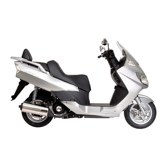
HOW TO USE THIS MANUAL CONTENTS This manual describes effective maintenance procedure for the S2-125 manufactured by DAELIM Motor Co., Ltd. To ensure safety and optimal operating conditions of the vehicle, carry out regular inspections according to the SERVICE INFORMATION maintenance schedule (Section 2). - Page 4 8. Flammable nitrogen gas is generated during charging the battery so charging must be performed in well-ventilated area and free of the open fire and spark. SERVICE RULES 1. Parts and lubrication oil must be DAELIM genuine or 2. Before maintenance, remove deposit or dust from the recommended parts.
- Page 5 SERVICE INFORMATION 3. Store the parts of each system discriminatively to install 4. After removing gasket, O-ring, piston pin clip and cotter each part in the right place. pin, always replace them with the new one. When removing the snap ring, it can be easily missed after transformation or installation.
- Page 6 SERVICE INFORMATION 11. Maintenance needed to use the specialized tools must 12. Never reuse the ball bearing removed with the ball be performed with the right tool. applied pressure when removing press-fitted the bearing. 13. Check the smooth rotation of inner or outer race of the 14.
- Page 7 SERVICE INFORMATION 19. Install the oil seal so that the manufacturer marked 20. Connect the tube until the tube fully inserted in the surface directs outer surface.(direction not covered joint. Install the clip if it is supplied. Replace the tube with oil) having slacked end.
- Page 8 SERVICE INFORMATION CAUTION WHEN WIRING •Each cord must be connected depending on its color. •When measuring voltage or resistance of the cord When connecting different cord, attach color tube terminal using tester, contact the tester plug behind of around the connector. Connect the coupler to the the coupler.
- Page 9 SERVICE INFORMATION •Turn off the main switch before connecting/dis- •When disconnecting the coupler, disconnect it while connecting. holding the coupler body. Pull while holding the wire •Release the lock to disconnect the lock of the coupler. harness cord and do not remove the coupler connection. •The lock of the coupler has two types according to releasing method(press type and pull type) so release it properly according to the shape.
- Page 10 SERVICE INFORMATION •Insert the connector until the vinyl cover is fully •When removing T-start, broaden the groove of T-start inserted into the terminal. using the wiring driver and release the torque. •The opening of the vinyl cover must face at the ground •Connect the harness and the hose to T-start and then direction but in case of the plain connector, the draining insert until the groove is locked.
- Page 11 SERVICE INFORMATION •In case that the wire harness is contacted with the end or •The wire must not hang down or be pulled excessively. the sharp edge, protect both parts with tube or tape. NOT TO PULL! •If necessary, lock the wire harness properly. •When mounting parts, make sure that the wire harness is not pressed by the parts.
-
Page 12: Serial Number Location
SERVICE INFORMATION SERIAL NUMBER LOCATION FRAME SERIAL NUMBER LOCATION ENGINE SERIAL NUMBER LOCATION ENGINE SERIAL NUMBER LOCATION FRAME SERIAL NUMBER LOCATION... -
Page 13: Specifications
SERVICE INFORMATION SPECIFICATIONS ITEM SPECIFICATIONS OVERALL LENGTH 2,110 mm OVERALL WIDTH 745 mm OVERALL HEIGHT 1,356 mm WHEEL BASE 1,481 mm DIMENSIONS SEAT HEIGHT 760 mm GROUND CLEARANCE 121 mm DRY WEIGHT 150 kg GROSS WEIGHT 294 kg TYPE Underbone FRONT SUSPENSION / STROKE Telescopic REAR SUSPENSION / STROKE... - Page 14 SERVICE INFORMATION ITEM SPECIFICATIONS TYPE / VENTURI BORE CV type ( vacuum ) ф25 mm MODEL MARK CVK 116 A CHOKE TYPE Auto-bystarter MAIN JET # 102 CARBURETOR PILOT SCREW INITIAL SETTING 2 and ½ trust out FLOAT LEVEL 20.5 mm IDLE SPEED 1.700±100 ( rpm ) CLUTCH TYPE...
- Page 15 SERVICE INFORMATION TORQUE VALUES ENGINE THREAD DIA ITEM Q’TY TORQUE VALUE REFERENCE (mm) OIL FILTER CAP 1.1 kgf·m OIL DRAIN PLUG BOLT 2.5 kgf·m VALVE ADJUST SCREW LOCK NUT 0.8 kgf·m CYLINDER HEAD BOLT 1.0 kgf·m FLYWHEEL BOLT 5.5 kgf·m DRIVE FACE NUT 7.5 kgf·m CLUTCH OUTER BOLT...
-
Page 16: Standard Torque Values
SERVICE INFORMATION STANDARD TORQUE VALUES ITEM TORQUE VALUE ITEM TORQUE VALUE 5mm BOLT, NUT 5mm SCREW 0.5 kgf·m 0.4 kgf·m 6mm BOLT, NUT 6mm SCREW 1.0 kgf·m 0.9 kgf·m 8mm BOLT, NUT 6mm FLANGE BOLT, NUT 2.2 kgf·m 1.2 kgf·m 10mm BOLT, NUT 8mm FLANGE BOLT, NUT 3.5 kgf·m... - Page 17 SERVICE INFORMATION WIRING DIAGRAM CABLE GUIDE LIGHTING CORD (EXPORT USE ONLY) WINKER SW. CORD WINKER SW. CORD LIGHTING SW. CORD (EXPORT USE ONLY) FR. BRAKE HOSE HAZARD SW. WIRE (DOMESTIC USE ONLY) RR. BRAKE HOSE FUEL NECK EARTH WIER THROTTLE CABLE AUTO CHOKE WIRE HORN WIRE BATTERY BOX...
- Page 18 SERVICE INFORMATION RR. BRAKE HOSE CABLE GUIDE FR. BRAKE HOSE WINKER SW. CORD LIGHTING SW. CORD (EXPORT USE ONLY) HORN WIRE THROTTLE CABLE THROTTLE CABLE SEAT LOCK CABLE SEAT LOCK CABLE HAZARD SW. WIER (DOMESTIC USE ONLY) COMBI. METER COUPLER FUEL SUPPLY TUBE RR.
- Page 19 SERVICE INFORMATION HEAD LIGHT RELAY WINKER RELAY EARTH CABLE BATTERY BOX COUPLER *NOTE - WHITE COLOR : EXPORT USE ONLY - BLACK COLOR : DOMESTIC USE ONLY REG. RECTIFIER REG. RECTIFIER CORD BATTERY + CABLE WIER CLIP ACG. CORD WIER CLIP START-MAGNETIC SW.
- Page 20 SERVICE INFORMATION FRAME BODY COMP. BATTERY + CABLE SPARE FUSE(15A) FUSE WIRE 12V 10AH BATTERY (MF) EARTH CORD (TO. FRAME) EARTH CABLE BATTERY + CABLE START-MAGNET SW. ASS’Y. START MOTOR CABLE TO. CARBULATOR TUBE CLIP FUEL PUMP TUBE CLIP TUBE CLIP TO.
- Page 21 MEMO...
-
Page 22: Service Information
2. INSPECTIONS/ADJUSTMENTS · · · · · · 2-1 BRAKE PAD/SHOE· · · · · · · · · · 2-7 SERVICE INFORMATION MAINTENANCE SCHEDULE ·· 2-3 BRAKE SYSTEM · · · · · · · · · · · · 2-7 FUEL LINE (FUEL TUBE) ·... - Page 23 INSPECTIONS / ADJUSTMENTS TORQUE VALUES SPARK PLUG 1.1kgf·m CYLINDER HEAD COVER BOLTS 1.0kgf·m VALVE ADJUSTING NUTS 1.1kgf·m TIMING HOLE CAP 0.6kgf·m TOOLS WRENCH 8X9mm ADJUST WRENCH COMPRESSION GAUGE...
-
Page 24: Maintenance Schedule
INSPECTIONS / ADJUSTMENTS MAINTENANCE SCHEDULE ● Carry out pre-operation check at each scheduled maintenance period based on the information described in the owner’s manual. I : INSPECT AND CLEAN, ADJUST, LUBRICATE OR REPLACE IF NECESSARY. R : REPLACE L : LUBRICATE C : CLEAN ●... -
Page 25: Fuel Line(Fuel Tube)
INSPECTIONS / ADJUSTMENTS FUEL LINE(FUEL TUBE) ● Remove the luggage box. ● Check the fuel tube of the fuel auto cock connected to the fuel tank and carburetor. If the fuel tube is cranked, damaged or leaks, replace it. THROTTLE GRIP OPERATION ●... -
Page 26: Air Cleaner
INSPECTIONS / ADJUSTMENTS AIR CLEANER ● Loosen the 6 screws securing the air cleaner case cover, remove it. ● Loosen the 2 screws securing the air cleaner element holder, remove it. ● Remove the air cleaner element. ● Wash away any accumulated dust or dirt, by gently squeezing it in non flammable or high flash point solvent. -
Page 27: Spark Plug
INSPECTIONS / ADJUSTMENTS SPARK PLUG CHECK GAP, 0.8 ~ 0.9mm DEPOSITS ● Remove the plug maintenance cover. ● Remove the spark plug cap and disassemble the plug. ● Check the plug for damage, contamination or deposits. ● If the spark plug is severely contaminated or damaged, raplace with a new one. -
Page 28: Carburetor Idle Speed
INSPECTIONS / ADJUSTMENTS CARBURETOR IDLE SPEED ● Remove the plug maintenance cover. (⇨4-5) ● Check the idle speed and adjust if necessary by turning the throttle stop screw. •Verify all engine adjustments satisfy specifications. Make adjustments, if necessary. •Heat the engine to make accurate idling inspection and adjustment. -
Page 29: Brake Fluid
INSPECTIONS / ADJUSTMENTS BRAKE FLUID ● Remove the brake fluid cover. ● Check the oil level inside the front brake reservoir. If the oil level is near the lower limit line, remove the reservoir diaphragm and fill DOT 3 and DOT 4 brake fluid to the top limit line. -
Page 30: Side Stand
INSPECTIONS / ADJUSTMENTS SIDE STAND ● Erect the main stand. ● Pull the lower end of the side stand, and see if it moves freely. ● If the side stand does not move smoothly, apply grease to the pivot area. ●... -
Page 31: Bolts, Nuts, Fasteners
INSPECTIONS / ADJUSTMENTS BOLTS, NUTS, FASTENERS ● Check all nuts and bolts of the frame during the regular maintenance to check if they meet the prescribed torque value. ● Check all pins, clips, hose clamps and cable stays. WHEELS/TIRES •Check the tire pressure when the tires have been cooled off. -
Page 32: External Parts
3. EXTERNAL PARTS SERVICE INFORMATION· · · · · · 3-1 UNDER COVER· · · · · · · · · · · · · · · · 3-5 SEAT· · · · · · · · · · · · · · · · · · · · · · · · · · · · 3-2 HANDLE COVER·... -
Page 33: Seat
EXTERNAL PARTS SEAT ● Release the seat lock by turning the main switch key to open the seat. ● Loosen the flange nuts and remove the seat. ● Install in the reverse order of removal. FLANGE NUTS FLANGE NUTS FLANGE NUTS FLANGE NUTS FLANGE NUTS FLANGE NUTS... -
Page 34: Luggage Box
EXTERNAL PARTS LUGGAGE BOX ● Remove the seat. ● Remove the pillion seat. ● Remove the luggage box top cover. ● Loosen the screws on the seat catch. ● Loosen the open stay nuts. ● Loosen the washer bolts. ● Remove the wire for the trunk lamp. ●... -
Page 35: Body Cover
EXTERNAL PARTS BODY COVER ● Remove the Rr. Grip R/L ● Remove the following parts - Seat - Luggage box - Center cover - Body side cover ● Loosen the special screw ● Loosen the body cover clip (R/L) ● Remove the wire for the tail light and pull the body cover backward. -
Page 36: Under Cover
EXTERNAL PARTS UNDER COVER ● Loosen the 4 special screws (R/L, 2Ea for each) to remove the under cover ● Install in the reverse order of removal HANDLE COVER ● Loosen the washer screw and tapping screw securing the under handle cover ●... -
Page 37: Windscreen
EXTERNAL PARTS WINDSCREEN ● Remove the front cover ● Loosen the 4 washer bolts and remove the windscreen ● Install in the reverse order of removal FRONT UNDER COVER A ● Remove the front cover and windscreen ● Loosen the 7 tapping screws securing the inner cover ●... -
Page 38: Inner Cover
EXTERNAL PARTS ● Loosen the 4 tapping screws securing the inner cover INNER COVER ● Remove the front cover and windscreen ● Remove the coolant reserve tank ● Remove the fuel tube clip ● Remove the breather tube ● Loosen the 3 screws securing the inner cover ●... -
Page 39: Front Fender
EXTERNAL PARTS FRONT FENDER ● Loosen the 4 screws (R/L, 2Ea for each) ● Install in the reverse order of removal REAL WHEEL MUDGUARD ● Loosen the 2 flange bolts of RH. ● Loosen the flange bolt securing the air cleaner and mudguard ●... -
Page 40: Lubrication System
LUBRICATION SYSTEM 4. LUBRICATION SYSTEM SERVICE INFORMATION · · · · · · 2-1 OIL PUMP · · · · · · · · · · · · · · · · · · 2-4 TROUBLESHOOTING · · · · · · · · · · 2-2 RADIATOR·... - Page 41 LUBRICATION SYSTEM TROUBLESHOOTING Oil level low •Oil consumption. •External oil leaks. •Worn piston ring or incorrect piston ring installation. •Worn valve guide or seal. Oil contamination •Oil or filter not changed often enough. •Faulty head gasket. •Worn piston rings. Low or no oil pressure •Clogged oil orifice.
-
Page 42: Engine Oil Level Inspection
LUBRICATION SYSTEM ENGINE OIL LEVEL INSPECTION ● Erect the motorcycle on the main stand. UPPER LINE ● Warm up the engine to heat the engine oil to an PROPER LINE appropriate level. LOWER LINE ● Stop the engine, and check the oil level line on the sight-glass installed on the LH. -
Page 43: Oil Pump
LUBRICATION SYSTEM OIL FILTER ELEMENT CHANGE ●Drain engine oil. (⇨4-3) ●Loosen the 3 flange bolts securing the oil filter cover, remove the oil filter cover. ●Remove the oil filter element and oil filter spring. OIL FILTER COVER ●Change the oil filter element with a new one. ELEMENT ●Check if the oil filter seal is in good condition. - Page 44 LUBRICATION SYSTEM OIL PUMP DISASSEMBLY ●Loosen the screw securing the oil pump plate. PUMP PLATE PUMP BODY INNER ROTOR ●Remove the oil pump body and the oil pump plate. ●Clean the oil pump body, inner and outer rotors with PUMP SHAFT fresh cleaning oil.
- Page 45 LUBRICATION SYSTEM OIL PUMP ASSEMBLY ●Clean all parts with fresh cleaning oil. PUMP PLATE PUMP BODY INNER ROTOR PUMP SHAFT OUTER ROTOR ROLLER2.5x11.8 ●Install the inner and outer rotors to the pump body. ●Assemble the pump shaft with setting pin. INNER ROTOR OUTER ROTOR ●Install the oil pump plate to the pump body.
- Page 46 LUBRICATION SYSTEM RADIATOR RADIATOR RADIATOR RADIATOR RADIATOR RADIATOR RADIATOR RADIATOR RADIATOR RADIATOR RADIATOR RADIATOR RADIATOR RADIATOR RADIATOR RADIATOR RADIATOR RADIATOR RADIATOR REMOVAL ●Remove the front cover. (⇨3-5) ●Remove the front wheel. (⇨12-4) ●Loosen the 2 oil bolts and the 4 drain cock packings from the main pipe bracket.
- Page 47 LUBRICATION SYSTEM RADIATOR INSTALLATION RADIATOR RADIATOR RADIATOR RADIATOR RADIATOR RADIATOR RADIATOR RADIATOR RADIATOR RADIATOR RADIATOR RADIATOR RADIATOR RADIATOR RADIATOR RADIATOR RADIATOR RADIATOR ●Tighten the 3 radiator setting flange bolts to the main pipe bracket. FLANGE BOLTS FLANGE BOLTS FLANGE BOLTS FLANGE BOLTS FLANGE BOLTS FLANGE BOLTS...
-
Page 48: Lubrication Points
LUBRICATION SYSTEM LUBRICATION SYSTEM LUBRICATION POINTS Unless specifically designated, use general grease to lubricate the lubrication points. For sliding parts not shown here, add oil or grease. CONTROL CABLE LUBRICATION Remove and clean the upper assembly of the throttle cable, and apply oil. If the cable has expanded, replace it. FRONT BRAKE LEVER PIVOT THROTTLE GRIP STEERING HEAD BEARING... - Page 49 MEMO...
-
Page 50: Fuel System
FUEL SYSTEM 5. FUEL SYSTEM AIR CLEANER · · · · · · · · · · · · · · 5-4 SERVICE INFORMATION · · · · 5-1 CARBURETOR · · · · · · · · · · · · · · 5-4 TROUBLESHOOTING ·... - Page 51 FUEL SYSTEM TROUBLESHOOTING Back firing The vehicle does not start. ● Ignition system is damaged. ● No gasoline in fuel tank. ● Mixture is too lean. ● Fuel is not coming out of carburetor. ● Too much fuel is flowing into cylinder. ●...
-
Page 52: Fuel Tank
FUEL SYSTEM FUEL TANK REMOVAL •Gasoline is extremely flammable. Avoid fire during work, and pay particular attention to electric sparks. Furthemore, the evaporated (gasified) gasoline is highly explosive. Work in a well-ventilated areas. ● Release the seat lock by turning the main switch key to open the seat. - Page 53 FUEL SYSTEM CARBURETOR DISASSEMBLY ● Remove the drain tube and air band hose. ● Loosen the 4 diaphragm cover setting screws. ● Remove the diaphragm cover. ● Remove the diaphragm spring, diaphragm assembly. ● Turn the jet needle with a ⊖ screwdriver, and remove the needle spring, spring holder, and jet needle from the vacuum piston.
- Page 54 FUEL SYSTEM FLOAT CHAMBER/FLOAT/JET DISASSEMBLY ● Loosen the 4 screws securing the float body. ● Remove the float pin, float, and float value. ● Check the float valve and valve seat for scores, scratches, clogging and damage. Replace if necessary. ●...
-
Page 55: Carburetor Cleaning
FUEL SYSTEM CARBURETOR CLEANING CARBURETOR BODY ● After removing all parts, blow open air and fuel passages in the carburetor body with compressed air. •Cleaning the air and fuel passages with a piece of wire will damage the carburetor body or fuel pump. MAIN JET SLOW JET PLUNGER ASS'Y... -
Page 56: Float Level Inspection
FUEL SYSTEM FLOAT LEVEL INSPECTION ● Install the float valve, float, float pin. ● Measure the float level with the float level gauge. FLOAT LEVEL : 13 mm TOOL : FLOAT LEVEL GAUGE ● If the level is out of specification and the float arm lip can be bent, adjust the float level by bending the lip. - Page 57 FUEL SYSTEM CABURETOR INSTALLATION ● Install the carburetor to the carburetor insulator. ● Tighten the carburetor insulator band screw. ● Tighten the setting screw securing the carburetor and set plate. ● Install the fuel tube to the carburetor. ● Install the wiring coupler of the auto bystarter. ●...
- Page 58 FUEL SYSTEM PILOT SCREW ADJUSTMENT ● Remove the carburetor maintenance cover. (⇨3-3) ① Turn the pilot screw clockwise until it seats lightly, then back it out to the specification given (1½). ② Warm up the engine to operating temperature (60℃). ③...
- Page 59 MEMO...
-
Page 60: Engine Removal/Installation
6. ENGINE REMOVAL/INSTALLATION INFORMATION· · · · · · · · · · 6-1 SERVICE ENGINE REMOVAL · · · · · · · · · · · · · · · · 6-2 SERVICE INFORMATION GENERAL SAFETY •Use a jack to remove or install the engine. Support the motorcycle with a jack firmly, taking precautions not to damage the frame, engine, cable or harness. -
Page 61: Engine Removal
ENGINE REMOVAL/INSTALLATION ENGINE REMOVAL ● Drain the engine oil. ● Release the seat lock by turning the main switch key to open the seat. ● Remove the following parts. -Luggage box (⇨3-2) -Center cover (⇨3-3) -Air cleaner (⇨2-5) -Carburetor (⇨5-3) ●... -
Page 62: Engine Installation
ENGINE REMOVAL/INSTALLATION ● Remove the RH./LH. radiator hose, remove the RH./LH. radiator hose from the frame setting clamp. RADIATOR HOSE ● Loosen the U-nut securing the engine hanger. ● Loosen the rear cushion lower bolt. ● Remove the engine. (with the rear swing arm and rear wheel attached) ●... - Page 63 LH. CRANKCASE COVER/CONTINUOUSLY VARIABLE TRANSMISSION LH. CRANKCASE COVER...
- Page 64 7. LH. CRANKCASE COVER /CONTINUOUSLY VARIABLE TRANSMISSION SERVICE INFORMATION· · · · · · 7-1 DRIVE BELT· · · · · · · · · · · · · · · · · · 7-6 TROUBLESHOOTING· · · · · · · · 7-1 MOVABLE DRIVE FACE·...
- Page 65 LH. CRANKCASE COVER/CONTINUOUSLY VARIABLE TRANSMISSION LH. CRANKCASE COVER REMOVAL ● Remove the 12 flange bolts securing LH. crankcase. ● Remove the LH. crankcase cover. ● Remove the gasket and dowel pin. INSTALLATION ● Install the new gasket and dowel pin after removing the gasket of the crankcase surface.
- Page 66 LH. CRANKCASE COVER/CONTINUOUSLY VARIABLE TRANSMISSION DRIVE BELT REMOVAL ● Remove the LH. crankcase cover. (⇨7-2 ) ● Hold the clutch outer using the universal holder and remove the nut. ● Remove the clutch outer. TOOL: UNIVERSAL HOLDER UNIVERSAL ·Use the special tool when loosening the lock nut. HOLDER Holding the rear wheel or rear brake will damage the final reduction system.
- Page 67 ● Replace the belt if the service limit is exceeded. WIDTH SERVICE LIMIT : 20.5mm ·Use only a genuine DAELIM replacement drive belt. ·Do not get oil or grease on the drive belt or pulley faces. Clean off any grease or oil before reinstalling.
-
Page 68: Movable Drive Face
LH. CRANKCASE COVER/CONTINUOUSLY VARIABLE TRANSMISSION ● Reinstall the driven pulley on the drive shaft with the drive belt attached. ● Hold the clutch outer using the universal holder. Tighten the nut to the specified torque. TORQUE VALUE : 5.0-6.0 kgf·m TOOL : UNIVERSAL HOLDER ●... - Page 69 LH. CRANKCASE COVER/CONTINUOUSLY VARIABLE TRANSMISSION MOVABLE DRIVE FACE INSPECTION WEIGHT ROLLER ● The weight rollers push on the movable drive face (by centrifugal force); worn or damaged weight rollers will interfere with this force. ● Check the rollers for wear or damage and replace as necessary.
- Page 70 LH. CRANKCASE COVER/CONTINUOUSLY VARIABLE TRANSMISSION ● Install the movable drive face on the crank shaft. BOSS MOVABLE DRIVE FACE ● Squeeze the drive belt into the drive face groove and pull the drive belt over the drive face shaft. DRIVE BELT ●...
- Page 71 LH. CRANKCASE COVER/CONTINUOUSLY VARIABLE TRANSMISSION CLUTCH/DRIVEN PULLEY REMOVAL ● Remove the LH. crankcase cover. ( 7-2) ) X h @ ) X ? g @ V / X g @ ? V / X ? f @ @ @ @ @ @ @ @ @ @ @ ? ? V / X f @ ? h f V / X ? e @ ? h f ? V / X e N 1 e...
- Page 72 LH. CRANKCASE COVER/CONTINUOUSLY VARIABLE TRANSMISSION ● Remove the seal collar from the driven pulley. SEAL COLLAR ● Remove the guide pins and guide pin rollers and the GUIDE PINS movable driven face. MOVABLE DRIVEN FACE GUIDE PIN ROLLER GUIDE PIN DRIVEN FACE ●...
- Page 73 LH. CRANKCASE COVER/CONTINUOUSLY VARIABLE TRANSMISSION CLUTCH / DRIVEN PULLEY INSPECTION Driven Face Bearing Inspection ● Check the inner bearing oil seal (if installed) for damage; replace as necessary. ● Check the needle bearing for damage or excessive play and replace as necessary. ●...
- Page 74 LH. CRANKCASE COVER/CONTINUOUSLY VARIABLE TRANSMISSION ● Check the following; -Movable driven face for damage or excessive wear. -Guide pin groove for damage or deformation. ● Replace damaged or worn parts as necessary. ● Measure the I.D. of the movable driven face; replace if the service limit is exceeded.
- Page 75 LH. CRANKCASE COVER/CONTINUOUSLY VARIABLE TRANSMISSION CLUTCH / DRIVEN PULLEY ASSEMBLY OIL SEAL ● Install new oil seals and O-rings on the movable driven pulley face. O-RING ● Install the movable face on the driven pulley face. ● Install the guide pins, or guide pins and guide pin rollers. GUIDE PINS MOVABLE DRIVEN FACE GUIDE PIN ROLLER...
- Page 76 LH. CRANKCASE COVER/CONTINUOUSLY VARIABLE TRANSMISSION CLUTCH/DRIVEN PULLEY INSTALLATION ● Install the clutch / driven pulley and drive belt onto the drive shaft. ● Install the drive belt. ( 7-3) ) X h @ ) X ? g @ V / X g @ ? V / X ? f @ @ @ @ @ @ @ @ @ @ @ ? ? V / X f @ ? h f V / X ? e...
- Page 77 A.C GENERATOR/STARTER CLUTCH STATOR COMP FLYWHEEL COOLING FAN RH. SHROUD...
-
Page 78: Generator/Starting Clutch
8. A.C GENERATOR / STARTER CLUTCH · · · · · · · · 8-1 RH. CRANKCASE COVER · · · · · · 8-4 SERVICE INFORMATION SHROUD· · · · · · · · · · · · · · · · · · · · · · · · · · · · 8-2 STARTER REDUCTION GEAR·... - Page 79 A.C GENERATOR/STARTER CLUTCH SHROUD REMOVAL ● Remove the following parts. -Luggage box (⇨3-2 ) -Center cover (⇨3-3 ) -Engine (⇨6-2 ) ● Loosen the RH. shroud 4 flange bolts and 4 tapping screws. LH. SHROUD ● Remove the RH. shroud. ●...
- Page 80 A.C GENERATOR/STARTER CLUTCH ● Install the universal holder on the flywheel. ● If the universal holder connot be used, remove the LH. crankcase cover at the left side of the crankshaft, and FLANGE NUT hold the drive face with the drive face holder. ●...
- Page 81 A.C GENERATOR/STARTER CLUTCH A.C GENERATOR INSTALLTION ● Install the stator to the RH. crankcase cover. ● Clean the tapered portion of the crankshaft. ● Clean the inside part of the flywheel. SCREW ● Check the woodruff key, install the flywheel by aligning the groove with the woodruff key.
- Page 82 A.C GENERATOR/STARTER CLUTCH ● Loosen the 9 RH. crankcase cover setting bolts. ● Remove the RH. crankcase cover. ● Remove the gasket and dowel pin. DOWEL PIN ● Remove the RH. crankcase cover oil seal. RH. CRANKCASE COVER ● Check the oil seal for wear or damage and replace with a new one as necessary.
-
Page 83: Starter Clutch
A.C GENERATOR/STARTER CLUTCH STARTER REDUCTION GEAR REDUCTION GEAR INSTALLATION SHAFT ● Install the starter reduction gear and shaft. ● Remove the gasket residues from the RH. crankcase. ● Install a new gasket and dowel pin. ● Tighten the RH. crankcase cover with setting bolts. ●... - Page 84 A.C GENERATOR/STARTER CLUTCH ● Remove the washer. STARTER CLUTCH ● Remove the starter driven gear and starter clutch. WASHER ● Check the starter driven gear and starter clutch for STARTER CLUTCH proper operation. ● Remove the starter clutch. STARTER CLUTCH INSPECTION ●...
- Page 85 A.C GENERATOR/STARTER CLUTCH STARTER CLUTCH INSTALLATION ● Install the starter oneway clutch set, starter driven gear and needle bearing to the starter clutch assembly. ● Install the starter clutch to the RH. crankshaft. ·When installing the starter clutch, match it with the groove accurately STARTER ONEWAY CLUTCH SET ●...
- Page 86 MEMO...
-
Page 87: Cylinder Head/Valve
CYLINDER HEAD / VALVE INLET VALVE ROCKER ARM CAM SHAFT HOLDER EXHAVST VALVE ROCKER ARM CAM SHAFT COMP INLET VALVE CARBURETOR INSULATOR EXHAVST VALVE CYLINDER HEAD COMP CYLINDER HEAD GASKET... - Page 88 9. CYLINDER HEAD / VALVES SERVICE INFORMATION· · · · 9-1 VALVES · · · · · · · · · · · · · · · · · · 9-6 TROUBLESHOOTING· · · · · · · · 9-2 VALVE GUIDES·...
- Page 89 CYLINDER HEAD / VALVE TOOLS VALVE GUIDE REAMER VALVE GUIDE DRIVER VALVE SPRING COMPRESSOR VALVE SEAT CUTTER SEAT CUTTER IN 37° (21.5mm) EX 37° (18.5mm) IN 45° (22.0mm) EX 45° (22.0mm) IN 55° (20.0mm) EX 55° (20.0mm) TROUBLESHOOTING Enging top-end problems useally affect engine performance. These can be diagnosed by a compression or leak down test, or by tracing noises to the top-end with a sounding rod or stethoscope.
- Page 90 CYLINDER HEAD / VALVE CAMSHAFT REMOVAL ● Remove the luggage box. (⇨3-2 ) ● Remove the center cover. (⇨3-3 ) ● Loosen the cylinder head cover bolts, remove the cover. ● Remove the shroud grommet B of the fan cover. ·The camshaft can be maintained without removing the engine.
- Page 91 CYLINDER HEAD / VALVE ● Remove the cam chain from the camshaft. CAM CHAIN ·Take precautions not to allow the cam chain to drop into the crankcase. ● Insert the 6mm bolt into the rocker arm shaft, and pulling bolts to remove the rocker arm shaft. ●...
- Page 92 CYLINDER HEAD / VALVE ● Manually turn the camshaft bearing outer race, and check if it turns smoothly. ● Check the bearing for wear or damage. ·Be sure to check the valve clearance. CAMSHAFT BEARING CYLINDER HEAD REMOVAL ● Remove the engine from the frame. (⇨6-2 ) ●...
-
Page 93: Cylinder Head Inspection
CYLINDER HEAD / VALVE ● Remove the valve spring, valve cotter, retainer, spring and valve. Using the valve spring compressor. TOOL : VALVE SPRING COMPRESSOR ·To prevent the loss of tension, do not compress the valve spring more than necessary. ·Mark the disassembled parts so that they can be reassembled into the original position later. - Page 94 CYLINDER HEAD / VALVE VALVE GUIDES VALVE GUIDE REAMER VALVE GUIDE REAMER VALVE GUIDE REAMER VALVE GUIDE REAMER VALVE GUIDE REAMER VALVE GUIDE REAMER VALVE GUIDE REAMER VALVE GUIDE REAMER VALVE GUIDE REAMER VALVE GUIDE REAMER VALVE GUIDE REAMER VALVE GUIDE REAMER VALVE GUIDE REAMER VALVE GUIDE REAMER VALVE GUIDE REAMER...
- Page 95 CYLINDER HEAD / VALVE ● Support the cylinder head and drive the old guides out of the combustion chamber side of the cylinder head. TOOL : VALVE GUIDE DRIVER VALVE GUIDE DRIVER ·Avoid damaging the head when driving the valve guide out.
- Page 96 CYLINDER HEAD / VALVE ● Remove the valve and inspect the valve seat face. ● The valve seat contact should be within the specified width and evenly all around the circumference. If the valve seat width is not within specification, reface the valve seat.
- Page 97 CYLINDER HEAD / VALVE ● Using a 55 degree cutter, remove the bottom ¼ of the old seat. 55° ● Using a 45 degree cutter, cut the seat to the proper width. SEAT WIDTH 45° ● If the contact area is too high on the valve, the seat must be lowered using a 37 degree flat cutter.
- Page 98 CYLINDER HEAD / VALVE ● After cutting the valve seat, apply lapping compound to the valve face, and insert the valve with a valve guide reamer. ·Do not excessively press and turn the valve to set it as it may cause damage. Gently strike and set the valve. ·The seat surface may become worn on one side if the valve is set in the same position.
- Page 99 CYLINDER HEAD / VALVE ● Tap the valve stems gently with a soft hammer to firmly seat the cotters. ·Take necessary precautions not to damage the valve. ● Apply engine oil to the new O-ring, and assemble it to the carburetor insulator groove. ●...
- Page 100 CYLINDER HEAD / VALVE CAMSHAFT ASSEMBLY IN. VALVE EX. VALVE ● Apply engine oil to the rocker arm shaft, and assemble ROCKER ARM ROCKER ARM the rocker arm to the camshaft holder. EX. ROCKER IN. ROCKER CAM SHAFT ARM SHAFT HOLDER ARM SHAFT ●...
- Page 101 CYLINDER HEAD / VALVE ● Apply engine oil to the camshaft, and install it on the cylinder head with the cam thread facing downward. ● Assemble the cam chain and cam sprocket after matching the cam sprocket timing mark in parallel with the top of the cylinder head.
- Page 102 CYLINDER HEAD / VALVE ● Fix the tensioner shaft with a hard clip. CAM CHAIN TENSIONER LIFTER ● Assemble a new gasket to the tensioner lifter, and install the tensioner lifter on the cylinder. ● Tighten the tensioner mounting bolts. TORQUE VALUE : 1.2 kgf ·m CLIP ●...
- Page 103 CYLINDER/PISTON CYLINDER TOP RING SECOND RING OIL RING CYLINDER GASKET PISTON 10-0...
-
Page 104: Cylinder/Piston
10. CYLINDER / PISTON SERVICE INFORMATION · · · · · · 10-1 PISTON / PISTON RING · · · · 10-3 TROUBLESHOOTING· · · · · · · · 10-1 CYLINDER INSTALLATION · · 10-5 CYLINDER· · · · · · · · · · · · · · · · · · 10-2 SERVICE INFORMATION GENERAL SAFETY ●... - Page 105 CYLINDER/PISTON CYLINDER REMOVAL ● Remove the engine from the frame. (⇨6-2 ) ● Remove the EX. pipe. (⇨3-8 ) ● Remove the camshaft. (⇨9-3 ) ● Remove the cylinder head. (⇨9-5 ) ● Remove the cam chain guide from the cylinder. ●...
- Page 106 CYLINDER/PISTON WARPAGE INSPECTION FEELER GAUGE ● Check the cylinder for warpage by placing a straight edge and feeler gauge across the stud holes. Replace the cylinder if the service limit is exceeded. SERVICE LIMIT : 0.02 mm STRAIGHT EDGE ·Any clearance between the cylinder and head due to damage or warpage will result in compression leaks and reduced performance.
- Page 107 CYLINDER/PISTON ● Insert the piston ring into the bottom of the cylinder squarely, using the piston. ● Measure the end gap using a feeler gauge. Replace the ring if the service limit is exceeded. ·Always replace piston ring as a set. FEELER GAUGE SERVICE LIMIT : TOP / SECOND : 0.50 mm OIL RING (SIDE RAIL) : 1.10 mm...
-
Page 108: Piston Installation
CYLINDER/PISTON PISTON / PISTON RING INSTALLATION ● Clean the piston heads, ring lands and skirts. ● Carefully install the piston rings onto the piston with MARK the markings facing up. ·Be careful not to damage the piston and rings during assembly. -
Page 109: Cylinder Installation
CYLINDER/PISTON ● Install new piston pin clips. ·Always use new piston pin clips. Reinstalling used piston pin clips may lead to serious engine damage. PISTON PIN CLIP ·Take care not to drop the piston pin clip into the crankcase. ·Set the piston pin clip in the groove properly. ·Do not align the clip’s end gap with the piston cutout. - Page 110 MEMO...
- Page 111 TRANSMISSION/CRANKSHAFT/CRANKCASE RH. CRANKCASE LH. CRANKCASE CRANKSHAFT 11-0...
-
Page 112: Transmission/Crankshaft/Crankcase
11. TRANSMISSION/CRANKSHAFT/CRANKCASE SERVICE INFORMATION· · · · · · · · 11-1 CRANKSHAFT REMOVAL· · · · · · 11-7 TROUBLESHOOTING · · · · · · · · · · 11-2 TRANSMISSION BEARING · · · · · · 11-8 TRANSMISSION ·... - Page 113 TRANSMISSION/CRANKSHAFT/CRANKCASE TORQUE VALUE CRANK CASE BOLT 1.0kg-m TOOLS -UNIVERSAL BEARING PULLER -BEARING REMOVER SET -REMOVER ASSEMBLY -REMOVER SHAFT -REMOVER HEAD -SLIDING WEIGHT -ASSEMBLY SHAFT TROUBLESHOOTING Engine Noise ● Connecting rod big and small ends loose. ● Crank pin bearing loose. Engine started but unable to move out ●...
- Page 114 TRANSMISSION/CRANKSHAFT/CRANKCASE TRANSMISSION DISASSEMBLY ● Loosen the drain bolt, drain the mission oil. ● Remove the LH. crankcase cover. (⇨7-2 ) ● Remove the continuously variable transmission. (⇨SECTION 7 ) ● Remove the EX. muffler. (⇨3-8 ) ● Remove the rear swing arm. (⇨13-8 ) ●...
- Page 115 TRANSMISSION/CRANKSHAFT/CRANKCASE ● Remove the final shaft and the counter shaft comp. FINAL SHAFT COUNTER SHAFT TRANSMISSION INSPECTION ● Check the drive shaft for wear or damage. DRIVE SHAFT ● Check the final shaft for wear or damage. FINAL SHAFT ● Check the counter shaft for wear or damage. COUNTER SHAFT 11-4...
- Page 116 TRANSMISSION/CRANKSHAFT/CRANKCASE TRANSMISSION BEARING INSPECTION ● Check that the bearing outer race fits the case tightly without play. ● Turn the inner race and check that the bearing turns smoothly and quietly. ● Replace the bearings if necessary. BEARING ● Install the bearing to the case with special tools. OUTER OUTER TOOLS : DRIVE HANDLE A...
- Page 117 TRANSMISSION/CRANKSHAFT/CRANKCASE ● Install a new gasket and dowel pin. ● Tighten the transmission cover with the setting bolts. ● Install the following parts. -Rear wheel (⇨13-5 ) -Rear swing arm (⇨13-8 ) -Rear brake caliper (⇨13-3 ) -EX. muffler (⇨ 3-8 ) -Continuously variable transmission (⇨SECTION 7 ) OIL CHECK BOLT -RH.
- Page 118 TRANSMISSION/CRANKSHAFT/CRANKCASE ● Remove the transmission bleeder tube. ● Remove the RH./LH. radiator hose from the RH. crankcase. RH. CRANKCASE ● Face the LH. crankcase downward, and remove the RH. crankcase from the LH. crankcase while tapping a few places on the LH. crankcase with a plastic hammer. ·Be careful not to distort the mating surface of the LH.
- Page 119 TRANSMISSION/CRANKSHAFT/CRANKCASE CRANKSHAFT INSPECTION DIAL MEASURING ● Place the crankshaft on a stand or V-block, and measure POINT GAUGE the crankshaft runout using dial gauge. SERVICE LIMIT : RIGHT : 0.1 mm LEFT : 0.1 mm ● Measure the side clearance by inserting the feeler gauge between the crankshaft and connecting rod big end as shown.
- Page 120 TRANSMISSION/CRANKSHAFT/CRANKCASE TRANSMISSION BEARING BEARING REPLACEMENT REMOVER SET LH. crankcase ● Use special tools to remove the drive shaft bearing. TOOLS : BEARING REMOVER SET REMOVER SHAFT REMOVER HEAD ● Remove the final shaft bearing and oil seal. ● Remove the countergear bearing. ●...
-
Page 121: Crankcase Installation
TRANSMISSION/CRANKSHAFT/CRANKCASE CRANKCASE INSTALLATION ● Install the dowel pins and a new gasket. DOWEL PIN ● Install the cam chain to the LH. crankcase. LH. CRANKCASE ● Install the RH. crankcase to the LH. crankcase. RH. CRANKCASE ·Make sure that the gasket is completely attached without any clearance. - Page 122 MEMO...
- Page 123 FRONT WHEEL/FRONT FORK/STEERING/BRAKE STEERING HANDLE STEERING STEM FRONT FORK FRONT DISK FRONT TIRE FRONT CASTING WHEEL 12-0...
-
Page 124: Front Wheel/Front Fork/Steering/Brake
12. FRONT WHEEL/FRONT FORK/STEERING/BRAKE INFORMATION· · · · · · · · 12-1 FRONT WHEEL INSTALLATION· · 12-7 SERVICE TROUBLESHOOTING· · · · · · · · · · 12-2 FRONT BRAKE· · · · · · · · · · · · · · · · 12-7 STEERING HANDLE ·... -
Page 125: Troubleshooting
FRONT WHEEL/FRONT FORK/STEERING/BRAKE TROUBLESHOOTING Hard steering Brake lever hard ● Steering bearing adjustment nut too tight. ● Clogged brake system ● Faulty steering stem bearings. ● Sticking caliper piston ● Damaged steering stem bearings. ● Caliper not sliding properly ● Insufficient tire pressure. ●... -
Page 126: Steering Handle
FRONT WHEEL/FRONT FORK/STEERING/BRAKE STEERING HANDLE REMOVAL ● Remove the upper handle cover and the under handle cover from the handle bar. ● Loosen the bolts securing the front and rear break master cylinder. ● Remove the front cover, front under cover and speedometer cover. -
Page 127: Front Wheel
FRONT WHEEL/FRONT FORK/STEERING/BRAKE ● Lubricate the throttle grip front end with grease and then install the throttle grip. ● Connect the throttle cable to the throttle grip. ● Install the right and left handlebar switches and tighten the screws. ·Adjust the throttle grip free play to the specified range of 2~6mm. -
Page 128: Front Wheel Bearing
FRONT WHEEL/FRONT FORK/STEERING/BRAKE WHEEL RIM ● Check the wheel rim runout. SERVICE LIMIT : RADIAL : 2.0mm replace if over AXIAL : 2.0mm replace if over DIAL GAUGE DIAL GAUGE DIAL GAUGE DIAL GAUGE DIAL GAUGE DIAL GAUGE DIAL GAUGE DIAL GAUGE DIAL GAUGE DIAL GAUGE... -
Page 129: Speedometer
FRONT WHEEL/FRONT FORK/STEERING/BRAKE SPEEDOMETER GEAR REPLACEMENT ● Remove the speedometer gear and washer from the speedometer gear box. ● Check the gear for wear or damage. ● Install the washer. ● Apply grease to the speedometer gear prior to assembling. ●... -
Page 130: Front Wheel Installation
FRONT WHEEL/FRONT FORK/STEERING ● Apply grease to the dust seal rim. ● Install the dust seal, and align the tangs of the speedometer gear retainer with the gear groove to assemble the speedometer gear box. SPEEDOMETER GEAR BOX SPEEDOMETER GEAR BOX SPEEDOMETER GEAR BOX SPEEDOMETER GEAR BOX SPEEDOMETER GEAR BOX... - Page 131 FRONT WHEEL/FRONT FORK/STEERING/BRAKE ·When servicing the brake system, use shop towels to cover rubber and plastic parts and coated surfaces to avoid being contaminated by brake fluid. ·When removing the brake fluid tube bolt, be sure to plug the tube end to avoid brake fluid leakage. DISASSEMBLY ●...
- Page 132 FRONT WHEEL/FRONT FORK/STEERING/BRAKE ·If there is any leak of fluid when installing new piston, it may indicate the side wear of the cylinder by the direction of the piston contacting face. In this case, the master cylinder must be replaced also. ●...
-
Page 133: Brake Fluid
FRONT WHEEL/FRONT FORK/STEERING/BRAKE ● Install the brake hose to the master cylinder with 2 new sealing washers and the hose bolt. TORQUE VALUE : 2.5~3.5 kgf·m ● Loosen the 2 flat screws, remove the oil cup cap, diaphragm plate and diaphragm. ●... - Page 134 FRONT WHEEL/FRONT FORK/STEERING/BRAKE ·Check the fluid level often, and replenish fluid if the amount of fluid is reduced to the lower level. ·Read the user’s manual carefully prior to disassembling or using the brake bleeder. ·Protect the bleeder valve with tape to prevent air from entering the bleeder valve.
-
Page 135: Brake Caliper
FRONT WHEEL/FRONT FORK/STEERING/BRAKE BRAKE CALIPER REMOVAL ● First drain the brake fluid from the hydraulic brake system. ● Remove the brake fluid tube bolt. ● Remove the two bolts securing the brake master cylinder. ● Remove the brake caliper. ·Pay attention not to let the brake fluid adhere to the parts because it can damage the painted surface. - Page 136 FRONT WHEEL/FRONT FORK/STEERING/BRAKE INSPECTION ● Check the caliper cylinder bore for scoring, scratches or other damage. ● Measure the caliper I.D. SERVICE LIMIT : 25.42mm ● Check the piston for scratches or wear. ● Measure the piston O.D. with a micrometer gauge. SERVICE LIMIT : 25.27mm ●...
-
Page 137: Front Fork
FRONT WHEEL/FRONT FORK/STEERING/BRAKE ● Apply the silicone grease to the boot. ● Connect the boot to the portion of the caliper. ● Install the pad spring in the caliper. ● Install the caliper pin bolt and the slide pin in the caliper. - Page 138 FRONT WHEEL/FRONT FORK/STEERING/BRAKE DISASSEMBLY ● Remove the fork pipe bolt. SPRING ·If the screw is completely loosened, the fork tube cap bolt may spring out by the force of the spring. Take due precautions. ·Remove the fork spring, and expand and release the fork pipe several times to drain fork oil.
-
Page 139: Front Fork Inspection
FRONT WHEEL/FRONT FORK/STEERING/BRAKE ● Remove the oil seal stop ring. OIL SEAL OIL SEAL OIL SEAL OIL SEAL OIL SEAL OIL SEAL OIL SEAL OIL SEAL OIL SEAL OIL SEAL OIL SEAL OIL SEAL OIL SEAL OIL SEAL OIL SEAL OIL SEAL OIL SEAL OIL SEAL... - Page 140 FRONT WHEEL/FRONT FORK/STEERING/BRAKE ● Check the slider bush contact face. ● If the slider bush is extensively damaged, replace the bottom case. FORK TUBE FRONT FORK ASSEMBLY ● Wash parts with clean oil prior to assembling. ● Assemble the rebound spring and thd fork piston to the BOTTOM CASE fork tube.
- Page 141 FRONT WHEEL/FRONT FORK/STEERING/BRAKE ● Install the oil seal stopper ring ● Accurately assemble the oil seal stop ring to the bottom OIL SEAL OIL SEAL OIL SEAL OIL SEAL OIL SEAL OIL SEAL OIL SEAL OIL SEAL OIL SEAL OIL SEAL OIL SEAL OIL SEAL OIL SEAL...
-
Page 142: Steering Stem
FRONT WHEEL/FRONT FORK/STEERING/BRAKE ● Install the front fork to the steering stem. ● Install the front fork setting bolts. TORQUE VALUE : 7.5 kgf·m ● Install the brake hose clip A to the RH. front fork. STEERING STEM REMOVAL ● Remove the following parts. -Handle cover -Handle bar -Front cover... - Page 143 FRONT WHEEL/FRONT FORK/STEERING/BRAKE ● Remove the steering top ball race from the head pipe. ● Remove the steering bottom race. ·Check all of the races and balls for damage or abnormal wear and replace as necessary. ·If the vehicle has been involved in an accident, examine the area around the steering head for crack.
- Page 144 MEMO...
- Page 145 REAR WHEEL / BRAKE / SUSPENSION / REAR SWING ARM 13-0...
-
Page 146: Rear Wheel/Brake/Suspension/Rear Swing Arm
13. REAR WHEEL/BRAKE/SUSPENSION/REAR SWING ARM SERVICE INFORMATION · · · · · · 13-1 PARKING WHEEL ·· · · · · · · · · · 13-5 TROUBLESHOOTING· · · · · · · · 13-2 REAR CUSHION · · · · · · · · · · ·13-7 REAR BRAKE ··... - Page 147 REAR WHEEL / BRAKE / SUSPENSION / SWING ARM TROUBLESHOOTING Wobble or vibration in motorcycle ● Tire pressure incorrect ● Faulty tire ● Bent rim ● Loose wheel bearing ● Swing arm bushing worn ● Wheel out of balance Soft suspension ●...
-
Page 148: Rear Brake
REAR WHEEL / BRAKE / SUSPENSION / SWING ARM REAR BRAKE REMOVAL ● Remove the muffler. ● Loosen the rear break tube bolt and remove the break tube. ● Loosen 2 bolts and remove rear break caliper. SETTING BOLTS INSPECTION ●... - Page 149 REAR WHEEL / BRAKE / SUSPENSION / SWING ARM ● Disassemble the piston seal and the dust seal. ● Clean the piston and inside of caliper with break fluid. INSPECTION ● Check the caliper cylinder bore for scoring, scratches PISTON or other damage.
- Page 150 REAR WHEEL / BRAKE / SUSPENSION / SWING ARM REAR WHEEL REMOVAL REAR CALIPER ● Support the motorcycle on the main stand. ● Loosen the parking brake rod adjust nut B, and remove the parking brake cable. ● Remove the brake arm joint B from the rear parking brake arm.
- Page 151 REAR WHEEL / BRAKE / SUSPENSION / SWING ARM REAR WHEEL INSPECTION ● Check the rim for wobbles by rotating the wheel. DIAL GAUGE SERVICE LIMIT : Radical 2.0mm Axial 2.0mm TOOL : DIAL GAUGE REAR WHEEL INSTALLATION ● Install the rear brake disk. FINAL SHAFT ●...
-
Page 152: Rear Cushion
REAR WHEEL / BRAKE / SUSPENSION / SWING ARM REAR CUSHION ADJUST ● Adjust the cushion spring according to the load condition. ● The rear cushion can be adjusted as below. soft medium hard REAR CUSHION REMOVAL ● Remove the luggage box. ●... - Page 153 REAR WHEEL / BRAKE / SUSPENSION / SWING ARM DISASSEMBLY REAR SWING ARM ● Disassemble the rear wheel outside collar from the rear swing arm. ● Disassemble the oil seal (28×42×7) and radial ball bearing (6302UU). ● Install in the reverse order of removal. AXLE U-NUT TORQUE VALUE - REAR WHEEL AXLE NUT : 6.0~8.0 kgf·m...
- Page 154 MEMO...
- Page 155 CHARGING SYSTEM REGULATOR RECTIFIER MAIN SWITCH A.C. GENERATOR YELLOW GREEN BLACK YELLOW (CABLE) MAIN YELLOW FUSE SWITCH (15A) ENGINE EARTH BLACK GREEN REGULATOR FRAME RECTIFIER BATTERY EARTH AC.GENERATOR (12V 10AH) 14-0...
-
Page 156: Charging System
14. CHARGING SYSTEM INFORMATION· · · · · · · · · · · · 14-1 CHARGING SYSTEM INSPECTION· · 14-3 SERVICE TROUBLESHOOTING· · · · · · · · · · · · · · · · 14-2 A.C. GENERATOR INSPECTION · · · · 14-4 BATTERY ·... - Page 157 CHARGING SYSTEM TROUBLESHOOTING No power (Key turned on) Low power (Engine running) ● Dead battery. ● Battery undercharged. ● Battery is failing. -Low fluid level. ● Charging system failure. -Low specific gravity. -Charging system failure. ● Disconnected battery cable. Intermittent power ●...
- Page 158 CHARGING SYSTEM BATTERY ● Remove the seat and luggage box. ● Loosen the screws secuning the battery cover and remove the battery cover. ● Remove the battery. ● First disconnect the negative “⊖” battery cable, and then disconnect the positive “⊕” cable. ·When disconnecting the battery positive ⊕...
-
Page 159: Charging System Inspection
CHARGING SYSTEM CHARGING SYSTEM INSPECTION LEAK TEST ● Trun off the ignition switch, and disconnect the ground (-) cable from the battery. ● Connect an ampere meter between negative (-) terminal and ground cable. ● With the ignition switch off, measure the leakage current. LEAK CURRENT : Not to exceed 0.5A(max) TOOL : DIGITAL TESTER ·When measuring current using a tester, set it to a... - Page 160 CHARGING SYSTEM REGULATOR RECTIFIER INSPECTION ● Remove the luggage box. ● Remove the regulator rectifier coupler. ● Measure each terminal. RESISTANCE VALUE Unit : ㏀, (20℃) Tester ⊕ Tester ⊖ ∞ ∞ ∞ ∞ 25-40K ∞ ∞ ∞ ∞ ∞ ∞...
- Page 161 IGNITION SYSTEM BATTERY REGULATOR RECTIFIER IGNITION UNIT MAIN SWITCH A.C. GENERATOR SIDE STAND SWITCH SPARK IGNITION COIL PLUG MAIN SWITCH GREEN BLUE/YELLOW GREEN FUSE (15A) AC.GENERATOR GREEN BATTERY PULSE CDI UNIT (12V 10AH) GENERATOR 15-0...
-
Page 162: Ignition System
15. IGNITION SYSTEM SERVICE INFORMATION· · · · · · · · 15-1 IGNITION COIL INSPECTION· · · · 15-5 TROUBLESHOOTING· · · · · · · · · · 15-3 IGNITION TIMING INSPECTION· · 15-6 CDI UNIT INSPECTION · · · · · · · · 15-7 SIDE STAND IGNITION CUT-OFF SWITCH·... - Page 163 IGNITION SYSTEM TROUBLESHOOTING No spark at plug. UNUSUAL CONDITION PROBABLE CAUSE (CHECK IN NUMERICAL ORDER) 1. The multitester impedance is too low. 2. Cranking speed is too slow. - Battery is undercharged (or operating force of the kick starter is weak).
- Page 164 IGNITION SYSTEM CDI UNIT INSPECTION CDI IGNITION CIRCUIT INSPECTION ·Follow the steps described in the troubleshooting flow chart when servicing the ignition system. ● Release the seat lock with the main key. ● Remove the luggage box. (⇨3-3) ● Disconnect the coupler from the CDI unit, and check the ignition system circuits from the wiring coupler side.
- Page 165 IGNITION SYSTEM IGNITION COIL INSPECTION ● Remove the seat lock with the main key. ● Remove the luggage box. ● Remove the center cover. ● Remove the primary wire. ·Since the resistance value of the primary coil is inherently very small, it is difficult to distinguish it from a shorted wire.
- Page 166 IGNITION SYSTEM IGNITION TIMING INSPECTION ·As the system uses the CDI unit, the ignition timing need not be adjusted. Check the ignition system if the ignition timing is incorrect. ● Start and warm up the engine. ● Remove the plug maintenance cover. TIMING CHECK ●...
- Page 167 IGNITION SYSTEM REMOVAL ● Remove the floor mat. ● Remove the center cover. (⇨3-3) ● Remove the RH. floor side cover. (⇨3-4) ● Remove the coupler of the side stand switch. ● Remove the LH. floor side cover. (⇨3-4) ● Loosen the side stand switch mounting 2 bolts. ●...
- Page 168 MEMO...
-
Page 169: Starter System
STARTER SYSTEM STOP SWITCH BATTERY MAIN SWITCH STARTER MOTOR STARTER RELAY CABLE CABLE GREEM/YELLOW STOP LAMP GREEM/YELLOW STARTER YELLOW/RED MOTOR GREEN STARTER RR.STOP FR.STOP SWITCH SWITCH SWITCH GREEN MAIN FUSE SWITCH (15A) BLACK BATTERY (12V 10AH) 16-0... - Page 170 16. STARTER SYSTEM SERVICE INFORMATION· · · · · · · · 16-1 STARTER MOTOR · · · · · · · · · · · · 16-4 STARTER DEVICES LOCATION· · 16-2 STARTER MAGNETIC SWITCH · · 16-7 TROUBLESHOOTING · · · · · · · · · · 16-3 SERVICE INFORMATION GENERAL SAFETY ·Always turn the ignition switch OFF before servicing the starter motor.
- Page 171 STARTER SYSTEM TROUBLESHOOTING Starter motor will not turn. ● Check for a blown main fuse before servicing. ● Check that the stop light is correctly adjusted. ● Check that the side stand is positioned in the condition under which the engine can be started. Connect the starter motor (+) terminal to the With the ignition switch “ON”and squeeze battery positive terminal.
-
Page 172: Starter Motor
STARTER SYSTEM STARTER MOTOR REMOVAL ● Release the seat lock with the main key. ● Remove the luggage box. (⇨3-3) ● Remove the starter motor cable from the starter FLANGE magnetic switch. BOLTS ● Loosen the 2 flange bolts securing the engine case, remove the battery earth cable and starter motor. - Page 173 STARTER SYSTEM ● Remove the brush spring, and then remove the brush. ● Measure the brush length. Replace the brush if it is worn beyond the service limit. BRUSH SERVICE LIMIT : 5 mm TOOL : VERNIER CALIPER ·If replacement, replace with a brush holder set. ●...
- Page 174 STARTER SYSTEM STARTER MOTOR ASSEMBLY ● Install the brush and brush spring to the brush hold set. ● Insert the brush terminal into the rear bracket, and install the terminal set and flange nut. ● Align the brush holder set with the rear bracket groove, and install the brush holder set.
- Page 175 STARTER SYSTEM STARTER MAGNETIC SWITCH STARTER MOTOR CABLE REMOVAL ● Release the seat lock with the main key. ● Remove the luggage box. (⇨3-3) ● Remove the center cover. (⇨3-3) ● Remove the battery (+) cable from the starter magnetic switch terminal.
- Page 176 STARTER SYSTEM OPERATION CHECK ● Disconnect the magnetic switch wire connector. ● Apply battery voltage between terminals, when the yellow / red wire is connected to the positive (+) battery terminal and the green / yellow wire to the negative (-) battery terminal. ●...
- Page 177 MEMO...
- Page 178 17. LIGHTS/SWITCHS/HORN SERVICE INFORMATION · · · · · · · · 17-1 HEADLIGHT CONTROLLER · · 17-4 TROUBLESHOOTING· · · · · · · · · · 17-1 COOLANT TEMPERATURE GAUGE· · 17-5 MAIN SWITCH· · · · · · · · · · · · · · 17-2 THROTTLE POSITION SENSOR·...
-
Page 179: Lights/Switchs/Horn
LIGHTS/SWITCH/HORN MAIN SWITCH ● Remove the front covers. ● Disconnect the ignition switch wire couplers. ● Check for continuity between the wire terminals. BLACK HANDLE SWITCH ● Remove the headlight. ● Disconnect the connector of handle switch. ● Check for continuity between teminals. ●... -
Page 180: Horn
LIGHTS/SWITCH/HORN PASSING SWITCH BAT2 BLACK BLUE COLOR DIMMER SWITCH BAT4 BAT2 COLOR BROWN/WHITE BLUE WHITE BLACK HORN ● Remove the horn from the wire connector. ● Connect the horn terminal with 12V battery. ● Normal if it sounds. FUEL UNIT ●... -
Page 181: Headlight Bulb Replacement
LIGHTS/SWITCH/HORN HEADLIGHT BULB REPLACEMENT ● Remove the front cover. ● Remove the headlight coupler and winker coupler. ● Remove the bulb socket of rubber boots. ● Remove the rubber boots. ● Replace the headlight bulb. •When replacing the bulb, be sure not to put finger and contaminated gloves prints on the headlight bulb, as they may create hot spots on the bulb and cause is to fail. -
Page 182: Wiring Diagram
18. WIRING DIAGRAM COMBINATION METER ASS’Y. 2P MINI 2P MINI 2P MINI Br/W BAT3 Br/L Br/L Br/L Br/W Br/W 6P MINI 18-1... - Page 183 SERVICE MANUAL 2004. 11. PRINTED NO COPY 2004. 11. PUBLICATION...
- Page 184 HEAD OFFICE (FACTORY) #58, SUNG SAN-DONG, CHANGWON, KYUNGNAM, KOREA TEL : (82-55) 239-7000 / FAX : (82-55) 239-7524 OVERSEAS SALES OFFICE #13-5, SUNG SOO 1DONG 1GA, SUNG DONG GU, SEOUL, KOREA TEL : (82-2) 498-6465 / FAX : (82-2) 467-9997 SM51-0411-01E...