Advertisement
Quick Links
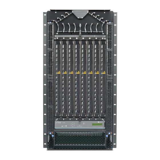
Quick Start Guide
QFX3008-I
IN THIS GUIDE
Step 1: Begin | 1
Step 2: Up and Running | 4
Step 3: Keep Going | 5
Step 1: Begin
IN THIS SECTION
Mount the QFX3008-I | 2
Connect to the Earth Ground and Attach Rear Support Anchors | 3
Connect to Single-Phase AC Power | 3
To install a Juniper Networks QFX3008-I Interconnect device, you need:
Mechanical lift rated for at least 750 lb (340.2 kg) (not provided)
Rack mounting shelf, rear support bracket, and two rear support anchors (provided)
32 mounting screws appropriate for your four-post rack or cabinet (12 to attach the rear support bracket to the rack,
6 to attach the rack mounting shelf to the rack, and 14 to attach the chassis to the rack) (not provided)
Screwdriver appropriate for your rack mounting screws (not provided)
Phillips (+) screwdriver, number 2, to remove and tighten screws
Grounding cable—minimum 2 AWG (33.6mm2), minimum 60º C wire—with appropriate grounding lug (provided) attached
by a licensed electrician
Advertisement

Related Manuals for Juniper QFX3008-I


Summary of Contents for Juniper QFX3008-I
- Page 1 Connect to the Earth Ground and Attach Rear Support Anchors | 3 Connect to Single-Phase AC Power | 3 To install a Juniper Networks QFX3008-I Interconnect device, you need: Mechanical lift rated for at least 750 lb (340.2 kg) (not provided)
- Page 2 These instructions apply only to a four-post 19-in. rack or cabinet installation and single-phase AC wiring trays. Mount the QFX3008-I 1. Place the rack in its permanent location, allowing adequate clearance for airflow and maintenance, and secure it to the building structure.
- Page 3 5. On the front of each front rack rail, partially insert a mounting screw 1 U below where you intend to install the chassis. 6. Install the four-post rack mounting shelf on the front rack rails. Rest the front of the four-post rack mounting shelf on the mounting screws you installed on the front rack rails.
-
Page 4: Step 2: Up And Running
6. Push the power cord into the slot in the adjustment nut. Turn the nut until it is against the base of the coupler and the slot in the nut is turned 90° from the top of the switch. 7. If the AC power source outlet has a power switch, set it to the OFF (O) position. 8. - Page 5 QFabric system. For detailed information about the following steps, see the QFX3000-G QFabric System Deployment Guide https://www.juniper.net/documentation/en_US/junos/information-products/pathway-pages/qfx-series/qfabric-deployment.html. 1. Connect up to four of the Gigabit Ethernet SFP ports on each control board on the QFX3008-I Interconnect device to the Juniper Networks EX4200 Ethernet Switch Virtual Chassis that connects the control plane network. Each device in your QFX3000-G QFabric system is connected to the control plane through the Virtual Chassis.
-
Page 6: Power Cable Warning (Japanese)
Before connecting the device to a power source, read the installation instructions in the QFX Series documentation. Do not install the QFX3008-I Interconnect device chassis without a mechanical lift. If the rack has stabilizing devices, install them in the rack before mounting or servicing the device in the rack. - Page 7 Juniper Networks, the Juniper Networks logo, Juniper, and Junos are registered trademarks of Juniper Networks, Inc. in the United States and other countries. All other trademarks, service marks, registered marks, or registered service marks are the property of their respective owners. Juniper Networks assumes no responsibility for any inaccuracies in this document. Juniper Networks reserves the right to change, modify, transfer, or otherwise revise this publication without notice.