Sign In
Upload
Manuals
Brands
YOKOGAWA Manuals
Measuring Instruments
digitalYEWFLO DY300
YOKOGAWA digitalYEWFLO DY300 Manuals
Manuals and User Guides for YOKOGAWA digitalYEWFLO DY300. We have
1
YOKOGAWA digitalYEWFLO DY300 manual available for free PDF download: User Manual
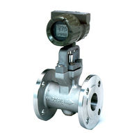
YOKOGAWA digitalYEWFLO DY300 User Manual (169 pages)
Vortex Flowmeter FOUNDATION Fieldbus Communication Type
Brand:
YOKOGAWA
| Category:
Measuring Instruments
| Size: 5.52 MB
Table of Contents
Table of Contents
2
1 Introduction
7
Using this Instrument Safety
8
Warranty
9
ATEX Documentation
10
2 Amplifier for Fieldbus Communication
11
3 About Fieldbus
12
Outline
12
Internal Structure of Digitalyewflo
12
System/Network Management VFD
12
Function Block VFD
12
Logical Structure of each Block
13
Wiring System Configuration
13
4 Getting Started
14
Connection of Devices
14
Host Setting
15
Power-On of Digitalyewflo and Bus
15
Integration of DD
16
Reading the Parameters
16
Continuous Record of Values
16
Generation of Alarm
17
5 Configuration
18
Network Design
18
Network Definition
18
Function Block Link Definitions
19
Setting of Tags and Addresses
20
Communication Setting
21
VCR Setting
21
Function Block Execution Control
22
Block Setting
23
Link Objects
23
Trend Objects
23
View Objects
24
Function Block Parameters
24
6 Explanation of Basic Items
32
Setting and Changing Parameters for the Whole Process
32
Transducer Block Parameters
33
AI Function Block Parameters
35
Parameters of DI Function Block
37
Integral LCD Indicator
37
7 In-Process Operation
39
Mode Transition
39
Generation of Alarm
39
Indication of Alarm
39
Alarms and Events
41
Simulation Function
41
8 Device Status
42
9 General Specifications
45
Standard Specifications
45
Model and Suffix Codes
47
Optional Specifications
48
10 Explosion Protected Type Instrument
52
Atex
52
Iecex
60
Csa
62
Tiis
64
Appendix 1. List of Parameters
65
A1.1 Resource Block
65
A1.2 al Function Block
67
A1.3 Transducer Block
70
Appendix 2. Application, Setting and Change of Basic Parameters
76
A2.1 Applications and Selection of Basic Parameters
76
A2.2 Setting and Change of
77
Basic Parameters
77
A2.3 Setting the AI Function Blocks
77
A2.4 Setting the Transducer Block
79
A2.5 Setting the DI Function Blocks
81
Appendix 3. Operation of each Parameter in Failure Mode
82
Appendix 4. Function Diagrams of Function Blocks
97
A4.1 AI Function Block
97
A4.2 DI Function Block
97
Appendix 5. Integrator (It) Block
98
A5.1 Schematic Diagram of Integrator Block
98
A5.2 Input Process Section
99
A5.2.1 Determining Input Value Statuses
99
A5.2.2 Converting the Rate
99
A5.2.3 Converting Accumulation
100
A5.2.4 Determining the Input Flow Direction
100
A5.3 Adder
101
A5.3.1 Status of Value after Addition
101
A5.3.2 Addition
101
A5.4 Integrator
101
A5.5 Output Process
103
A5.5.2 Determining the Output Value
104
A5.5.3 Mode Handling
105
A5.6 Reset
105
A5.6.1 Reset Trigger
105
A5.6.2 Reset Timing
105
A5.6.3 Reset Process
106
A5.7 List of Integrator Block Parameters
107
APPENDIX 6. Enhanced ARITHMETIC (AR) BLOCK
109
A6.1 Schematic Diagram of Arithmetic Block
109
A6.2 Input Section
110
A6.2.1 Main Inputs
110
A6.2.2 Auxiliary Inputs
110
A6.2.3 Input_Opts
111
A6.2.4 Relationship between the Main Inputs and PV
111
A6.3 Computation Section
112
A6.3.1 Computing Equations
112
A6.3.2 Enhanced Computing Equations
112
A6.3.3 Compensated Values
113
A6.3.4 Average Calculation
113
A6.4 Output Section
113
A6.4.1 Mode Handling
114
A6.4.2 Status Handling
114
A6.5 List of the Arithmetic Block Parameters
115
A6.6 Example of Connection
117
A6.7 Setting Procedure of the Mass Flow Rate Calculation
118
Appendix 7. Link Master Functions
119
A7.1 Link Active Scheduler
119
A7.2 Link Master
119
A7.3 Transfer of las
120
A7.4 LM Functions
121
A7.5 LM Parameters
122
A7.5.1 LM Parameter List
122
A7.5.2 Descriptions for LM Parameters
124
A7.6 Trouble Shooting
126
Appendix 8. Pid Block
128
A8.1 Function Diagram
128
A8.2 Functions of PID Block
128
A8.3 Parameters of PID Block
129
A8.4 PID Computation Details
131
A8.5 Control Output
131
A8.6 Direction of Control Action
131
A8.7 Control Action Bypass
132
A8.8 Feed-Forward
132
A8.9 Block Modes
132
A8.10 Bumpless Transfer
133
A8.11 Setpoint Limiters
133
A8.11.1 When PID Block Is in AUTO Mode
133
A8.11.2 When PID Block Is in CAS or RCAS Mode
133
A8.12 External-Output Tracking
134
A8.13 Measured-Value Tracking
134
A8.14 Initialization and Manual Fallback (IMAN)
134
A8.15 Manual Fallback
135
A8.16 Auto Fallback
135
A8.17 Mode Shedding Upon Computer Failure
135
A8.18 Alarms
136
A8.18.2 Process Alarms
136
A8.19 Example of Block Connections
137
Appendix 9. DD Menu
138
Appendix 10. Method
147
A10.1 Transducer Block
147
A10.2 Enhanced AR Block
151
APPENDIX 11. SOFTWARE DOWNLOAD (Option /EE)
155
A11.1 Benefits of Software Download
155
A11.2 Specifications
155
A11.3 Preparations for Software Downloading
155
A11.4 Software Download Sequence
156
A11.5 Download Files
156
A11.6 Steps after Activating a Field Device
157
A11.7 Troubleshooting
158
A11.8 Resource Block's Parameters Relating to Software Download
158
A11.9 System/Network Management VFD Parameters Relating to Software Download
160
A11.9.1 Parameter List
160
APPENDIX 12. DEVICEVIEWER WINDOW EXECUTED from PRM (Plant Resource Manager)
163
Revision Information
168
Advertisement
Advertisement
Related Products
YOKOGAWA DY30
YOKOGAWA DY025-/R1
YOKOGAWA DY100-/R1
YOKOGAWA DY200-/R1
YOKOGAWA digitalYEWFLO DY040/R2
YOKOGAWA digitalYEWFLO DY050/R2
YOKOGAWA digitalYEWFLO DY080/R2
YOKOGAWA digitalYEWFLO DY100/R2
YOKOGAWA digitalYEWFLO DY150/R2
YOKOGAWA DY040-/R1
YOKOGAWA Categories
Measuring Instruments
Test Equipment
Transmitter
Controller
Media Converter
More YOKOGAWA Manuals
Login
Sign In
OR
Sign in with Facebook
Sign in with Google
Upload manual
Upload from disk
Upload from URL