Sign In
Upload
Manuals
Brands
YASKAWA Manuals
Controller
JEPMC-MP2300S-E
YASKAWA JEPMC-MP2300S-E Manuals
Manuals and User Guides for YASKAWA JEPMC-MP2300S-E. We have
5
YASKAWA JEPMC-MP2300S-E manuals available for free PDF download: User Manual, Manual
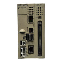
YASKAWA JEPMC-MP2300S-E User Manual (557 pages)
Built-in Motion Module. Machine Controller
Brand:
YASKAWA
| Category:
Control Unit
| Size: 11 MB
Table of Contents
2 Settings and Installation
34
Safety Information
6
Safety Precautions
7
Revision History
18
Specifications
27
Table of Contents
34
LED Indicators and Switch Settings
35
External Appearance
35
Indicators
35
Module Status Indication
35
Switch Settings
37
Applicable Machine Controllers for SVB-01 Modules
39
Mounting/Removing SVB-01 Modules
40
Mounting an SVB-01 Module
40
Removing SVB-01 Modules for Replacement
42
3 Self-Configuration and Created Definition Files
45
Self-Configuration Overview
46
How to Execute Self-Configuration
48
System Startup Using Self-Configuration
49
Starting the System for First Time
49
System Startup When Adding Electronic Devices
51
System Startup When Replacing Electronic Devices
53
Self-Configuration and Definition Files
54
Module Configuration Definition
55
Engineering Tool MPE720 Version
55
MECHATROLINK Transmission Definition
58
SVB Definition
64
Current Value and Setting Data in SVB
72
Precautions When Saving SERVOPACK Parameters
79
4 Motion Parameters
80
Motion Parameters Register Numbers
81
Motion Parameter Register Numbers for MP2000 Series Machine Controllers
81
Motion Parameters Setting Window
83
How to Open the Motion Parameter Setting Windows
83
Motor Type and Related Alarms
84
Motion Parameter Lists
85
Fixed Parameter List
85
Setting Parameter List
87
Register no
87
Name
87
Ow0F
90
Monitoring Parameter List
93
MP2000 Series Machine Controller Parameter Details
97
Motion Fixed Parameter Details
97
Motion Setting Parameter Details
104
Motion Monitoring Parameter Details
137
5 Motion Parameter Setting Examples
152
Electronic Gear
153
Example Setting of Motion Parameters for the Machine
153
Reference Unit
153
Axis Type Selection
155
Position Reference
156
Speed Reference
160
Acceleration/Deceleration Settings
163
Acceleration/Deceleration Filter Settings
164
Linear Scale Pitch and Rated Speed
165
6 Motion Commands
166
Motion Commands
168
Motion Command Table
168
Motion Commands Supported by SERVOPACK Models
169
Motion Command Details
170
Position Mode (POSING) (Positioning)
170
Latch Target Positioning (EX_POSING) (External Positioning)
176
Zero Point Return (ZRET)
181
Interpolation (INTERPOLATE)
201
Interpolation Mode with Latch Input (LATCH)
205
Jog Mode (FEED)
209
Relative Position Mode (STEP) (Step Mode)
213
Set Zero Point (ZSET)
217
Change Acceleration Time (ACC)
219
Change Deceleration Time (DCC)
221
Change Filter Time Constant (SCC)
223
Change Filter Type (CHG_FILTER)
225
Change Speed Loop Gain (KVS)
227
Change Position Loop Gain (KPS)
229
Change Feed Forward (KFS)
231
Read User Constant (PRM_RD)
233
Write User Constant (PRM_WR)
235
Alarm Monitor (ALM_MON)
237
Alarm History Monitor (ALM_HIST)
239
Clear Alarm History (ALMHIST_CLR)
241
Absolute Encoder Reset (ABS_RST)
243
Speed Reference (VELO)
246
Torque /Thrust Reference (TRQ)
250
Phase References (PHASE)
254
Change Position Loop Integral Time Constant (KIS)
258
Stored Parameter Write (PPRM_WR)
260
Multiturn Limit Setting (MLTTRN_SET)
262
Motion Subcommands
266
Motion Subcommand Table
266
Motion Subcommand Settings
266
Motion Subcommand Details
267
No Command (NOP)
267
Read User Constant (PRM_RD)
268
Write User Constant (PRM_WR)
270
Status Monitor (SMON)
272
Read Fixed Parameters (FIXPRM_RD)
274
7 Switching Commands During Execution
276
Switchable Motion Commands and Subcommands
277
Switching between Motion Commands
277
Setting a Subcommand During Command Execution
279
Motions after Switching Motion Commands
280
Switching from POSING
281
Switching from EX_POSING
285
Switching from ZRET
289
Switching from INTERPOLATE
292
Switching from ENDOF_INTERPOLATE or LATCH
295
Switching from FEED
296
Switching from STEP
300
Switching from ZSET
303
Switching from VELO
304
Switching from TRQ
309
Switching from PHASE
314
8 Control Block Diagrams
318
Position Control
319
Control Block Diagram for Position Control
323
Phase Control
325
Control Block Diagram for Phase Control
329
Torque Control
331
Control Block Diagram for Torque Control
335
Speed Control
337
Control Block Diagram for Speed Control
341
9 Absolute Position Detection
343
Absolute Position Detection Function
344
Outline of the Function
344
Reading Absolute Data
344
Finite Length/Infinite Length Axes and Absolute Position Detection
345
Setting Procedure of Absolute Position Detection Function
346
System Startup Flowchart
346
Initializing the Absolute Encoder
347
Absolute Position Detection for Finite Length Axes
348
Parameter Settings for Finite Length Axes
348
Setting the Zero Point for a Finite Length Axis
351
Turning on the Power after Setting the Zero Point of Machine Coordinate System
354
Absolute Position Detection for Infinite Length Axes
355
Simple Absolute Infinite Length Position Control
355
Setting the Zero Point and Turning on Power as Simple Absolute Positions
360
Turning on the Power after Setting the Zero Point
361
Infinite Length Position Control Without Simple Absolute Positions
361
10 Settings for Connecting Inverters
370
Specifications for Communications with Connected Inverters
371
Operation Precautions
373
Operation Procedure
375
10.2 Operating Inverters Using an MPE720
373
Input Command
377
Manually Allocating Inverters
380
I/O Options
381
Command Details
386
Subcommand Details
391
10.3 Main Commands and Subcommands
386
Motion Parameter Details
397
Fixed Parameter List
397
Setting Parameter List
398
0: Disabled, 1: Enabled
399
Ow10
402
Monitoring Parameter List
406
Bit 2: Multi-Function Input Command S3
408
Bit 3: Multi-Function Input Command S4
408
Bit 4: Multi-Function Input Command S5
408
Bit 5: Multi-Function Input Command S6
408
Bit 6: Multi-Function Input Command S7
408
Bit 9: Multi-Function Analog Input A3
408
Bit A: Multi-Function Input Terminal
408
Bit B: Multi-Function Analog Input A1
408
Bit C: Encoder Counter
408
Bits D to F Reserved by the System
408
10.5 Inverter Alarm and Warning Codes
420
Communication Warnings
420
Communication Alarm
420
Optional Interface Settings
420
11 Utility Functions
422
User Constants Self-Writing Function Enabled) - - - - - - - - - - - - - - - - - - - - - - - - - - - - - -
422
Controlling Vertical Axes
424
Holding Brake Function of the SERVOPACK
424
Connections to Σ-II Series SGDH Servopacks, Σ-III Series SGDS Servopacks
424
Σ-V Series SGDV Servopacks, and Σ-7 Series SGD7S Servopacks
424
Connections to Σ-I Series SGDB SERVOPACK
427
Connections to Σ-I Series SGD SERVOPACK
429
Overtravel Function
431
Connections to Σ-II Series SGDH Servopacks, Σ-III Series SGDS Servopacks, Σ-V Series SGDV Servopacks, and Σ-7 Series SGD7S Servopacks
431
Connections to Σ-I Series SGDB or SGD SERVOPACK
434
Software Limit Function
436
Fixed Parameter Settings
436
Processing after an Alarm Occurs
437
Modal Latch Function
438
Bank Switching Function
439
Bank Switching Specifications
439
Bank Switching Function Unsupported Motion Commands
439
SERVOPACK Parameter Settings for Bank Switching
439
Bank Member Setting
441
Parameters Updated When a MECHATROLINK Connection Is Established
444
Parameters Updated When a MECHATROLINK Connection Is Established
445
Parameters Updated When a Setting Parameter Is Changed
445
Parameters Updated When a Motion Command Is Executed
446
Parameters Updated During Self-Configuration
447
Precautions When Using Σ-V-Series SGDV Servopacks
450
Software Limit Settings
450
When the Tuning-Less Function Is Enabled
450
Saving the Parameter Bank Data
450
Motion Command Operation for External Latches with DC Power Input Σ-V-Series Servopacks
451
Precautions When Using Σ-7-Series SGD7S Servopacks with Rotary Servomotors
452
SGD7S Electronic Gear Ratio Settings
452
Link Assignment
452
Number of Pulses Per Motor Rotation
452
Motion Image
452
Software Limit Settings
453
When the Tuning-Less Function Is Enabled
453
Saving the Parameter Bank Data
453
Troubleshooting
454
Overview - - - - - - - - - - - - - - - - - - - - - - - - - - - - - - - - - - - - - - - - - - - - - - - - -
503
Appendix A System Registers Lists
507
A.3 Program Software Numbers and Remaining Program Memory Capacity Name - - - - - - - - - - - -
507
Appendix B Settings When Connecting MECHATROLINK Compatible I/O Modules
522
Appendix C Initializing the Absolute Encoder
522
Appendix D Setting the Multiturn Limit
522
Appendix E Fixed Parameter Setting According to Encoder Type and Axis Type
522
I.3 Motion Parameters that Can be Used in Servo Driver Transmission Reference Mode - - - - - -
542
Parameter Settings for Simple Absolute Infinite Length Position Control - - - - - - - - - - - - - - -
551
Advertisement
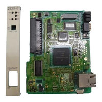
YASKAWA JEPMC-MP2300S-E User Manual (462 pages)
Machine Controller, Basic Module
Brand:
YASKAWA
| Category:
Controller
| Size: 14 MB
Table of Contents
1 Overview
15
Table of Contents
15
MP2300S Features
16
MP2300S Configuration
17
Basic Module Appearance
17
MP2300S Modules
18
System Configuration
19
Example
19
Example of Distributed Synchronizing System
20
MECHATROLINK-Compatible Devices
21
Servopacks
21
Modules
21
Cables and Accessories
22
Cables
22
Accessories and Options
23
Software (Programming Tool)
23
2 Specifications and Functions
25
Specifications
26
General Specifications
26
Product Specifications
27
Function Lists
28
Basic Module
31
Outline of Functions
31
External Appearance, LED Indicators, and Switch Settings
32
Specifications
35
218IFA Module (Ethernet)
36
Built-In SVB Module
54
SVR Virtual Motion Module
71
M-EXECUTOR Module (Motion Program Executor)
74
Option Module
85
Option Module Overview List
85
Machine Controller MP2000 Series SVB/SVB
85
External Appearance
87
Basic Module
87
Basic Module with Metal Fittings
88
3 Mounting and Wiring
89
Mounting MP2300S
90
Method
90
MP2300S Mount Direction
95
Space Required for Mounting MP2300S
96
Replacing and Adding Optional Modules
97
Basic Module Connections
100
Connectors
100
Power Supply Connector
101
MECHATROLINK Connectors
102
Ethernet Connector Details
107
RLY out Connector Details
111
System Connection Example
113
4 System Start up and Easy Programming
115
Overview - - - - - - - - - - - - - - - - - - - - - - - - - - - - - - - - - - - - - - - - - - - - - - - - -
115
System Startup Overview
116
Preparation (Step 1)
117
Wiring
117
Self Configuration
119
Test Operation
120
Programming (Step 2)
123
Programming Procedure
123
Executing Motion (Step 3)
125
Registering Program Execution
125
Starting a Motion Program Using the Operation Control Panel
126
Starting Motion Program from an External Signal
127
Overview
127
Required Equipment
127
Creation Procedure
129
5 Outline of Motion Control Systems
133
Startup Sequence and Basic Operation
134
DIP Switch Settings
134
Startup Sequence
135
Startup Sequence Operation Details
136
LED Indicator Details
137
User Programs
138
Types and Execution Timing of User Program
138
Motion Programs
139
Sequence Program
160
Ladder Drawings (DWG)
163
Registers
168
Types of Registers
168
Data Types
171
How to Use Subscripts I, J
172
Register Designation
173
Self-Configuration
174
How to Execute Self-Configuration
175
Definition Information Updated with Self-Configuration
183
Precaution on Using MP2300S
186
Precautions When User Definition File Is Configured/Changed
186
Setting or Changing Module Configuration Definition Files
187
Setting and Changing the Scan Time
188
6 Ethernet Communications
191
Communication Methods
192
Communication with Other MP Series
193
When the MP2300S Acts as Slave (Automatic Receive Function Is Used)
193
Param no
201
When the MP2300S Acts as a Slave (Ladder Program Which Uses a MSG-RCV Function)
207
OUT Process Result
214
OUT Status
214
IN Connection Number
214
IN Option
222
IN Function Code
222
IN Remote CPU Number
222
When MP2300S Acts as Master (I/O Message Communication Function Is Used)
226
IN Coil Offset
235
IN Input Relay Offset
235
IN Input Register Offset
235
When the MP2300S Acts as Master (Ladder Program Which Uses MSG-SND Function)
239
IN Holding Register Offset
246
Communication with Touch Panel
255
When MP2300S Acts as Slave
255
Communication with PLC Manufactured by Mitsubishi Electric Corporation (MELSEC Protocol)
265
When the MP2300S Acts as Slave (Automatic Receive Function Is Used)
265
When the MP2300S Acts as Master (I/O Message Communication Function Is Used)
273
7 Slave CPU Synchronous Function
281
Overview - - - - - - - - - - - - - - - - - - - - - - - - - - - - - - - - - - - - - - - - - - - - - - - - - - - - - - - - - - -
281
Function
282
Overview
282
Requirements and Setting of Execution
283
Supported Version
283
Requirements to Execute Slave CPU Synchronous Function
283
How to Set up Slave CPU Synchronous Function
284
How to Execute Slave CPU Synchronous Function
287
Operation
289
Input/Output Register
289
How to Determine Slave CPU Synchronous State
295
Calculation of Slave CPU Synchronous Delay Time
296
How to Use Scan Counter
297
How to Determine Input Error
298
Management to Resume Slave CPU Synchronization
304
Precautions
308
Precautions on Usage
308
Effect of Error on Slave CPU Synchronous Operation
309
8 Maintenance, Inspection, and Troubleshooting
311
Inspection Items
312
Daily Inspections
312
Regular Inspections
313
Replacing the Basic Module Battery
314
Troubleshooting
315
Basic Flow of Troubleshooting
315
MP2300S Error Check Flowchart
316
LED Indicators
316
Troubleshooting System Errors
321
Motion Program Alarms
335
List of Causes for Command Error Completed Status
340
Troubleshooting Motion Errors
343
Appendices
355
Appendix A System Registers Lists
355
A.1 System Service Registers - - - - - - - - - - - - - - - - - - - - - - - - - - - - - - - - - - - - - - - - - - - - - - - - -
355
A System Registers Lists
356
System Service Registers
356
Scan Execution Status and Calendar
358
Program Software Numbers and Remaining Program Memory Capacity
358
B SERVOPACK Parameter Data Flow
359
Operations and Parameter Data Flow
359
C Initializing Servopacks
368
D Initializing the Absolute Encoder
369
E Motion Parameter Details
374
Fixed Parameter List
374
Setting Parameter List
376
Monitoring Parameter List
381
F How to Set up Communication Process
385
Preparation
385
Procedure
385
G MSG-SND/ MSG-RCV Functions
390
Message Transmit Function (MSG-SND
390
G.1.3 Message Transmit Function Parameter List (Param) Overview
394
Note: IN: Input, OUT: Output, SYS: for System Use
394
Send_Ok
397
Rec_Ok
397
Abort_Ok
397
Fmt_Ng
397
Seq_Ng
397
SYS Reserved
394
To 16 SYS Reserved
394
Code (Hex) Abbreviation U_SEND U_REC ABORT
417
Message Receive Function (MSG-RCV
429
Communication Buffer Channel
456
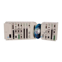
YASKAWA JEPMC-MP2300S-E User Manual (375 pages)
Machine Controller, Motion Module
Brand:
YASKAWA
| Category:
Controller
| Size: 3 MB
Table of Contents
Table of Contents
13
1 Overview
18
Module Overview and Features
19
Overview
19
Features
20
System Configuration Example
21
Specifications
22
Hardware Specifications
22
Functional Specifications
24
Performance Specifications
25
Applicable Servopacks
26
2 Settings and Installation
27
External Appearance and LED Indicators
28
External Appearance
28
LED Indicators
28
Module Status Indication
29
Applicable Machine Controllers for SVA-01 Modules
30
Mounting/Removing SVA-01 Modules
31
Mounting a SVA-01 Module
31
Removing SVA-01 Modules for Replacement
33
Module Connections
35
Connectors
35
Connection Procedure for 24-V Input Cable
36
CN1 and CN2 Connector Pin Arrangement
37
Cable Specifications and Connections
38
Cables
38
JEPMC-W2040--E Details
38
JEPMC-W2041--E Details
40
Restrictions for Feedback Pulse Inputs
43
Restrictions for SERVOPACK Pulse Output Frequency
43
Restrictions in SVA-01 Module Pulse Input Frequency
44
3 Setup
45
Setting Items
46
Module Configuration Definition of Machine Controller
47
How to Execute Self-Configuration
47
Opening the Module Configuration Window
48
Module Configuration Window
49
Manually Allocating Modules
50
SVA Definition
51
Opening the SVA Definition Window
51
Setting the SVA-01 Module Fixed Parameters
53
SERVOPACK Parameter Settings
54
SGDA SERVOPACK Parameter Settings
54
SGDB SERVOPACK Parameter Settings
55
SGDM, SGDH, SGDS, SGDV, and SGD7S SERVOPACK Parameter Settings
56
SERVOPACK Reference Offset Adjustment
57
Automatic Adjustment of the Analog Reference Offset
57
Manual Servo Tuning of the Speed Reference Offset
58
4 Operation Modes
60
Module Operation Mode Selection
61
Normal Operation Mode
62
Motion Parameters that Can be Used in Normal Operation Mode
62
DI/DO Signals in Normal Operation Mode
62
Simulation Mode
63
Motion Parameters that Can be Used in Simulation Mode
63
Position and Speed in Simulation Mode
63
Torque in Simulation Mode
63
Functions that Cannot be Simulated
63
Output Signals in Simulation Mode
64
General-Purpose I/O Mode
65
Motion Parameters that Can be Used in General-Purpose I/O Mode
65
Correspondence between Motion Parameter and Connector Pin Number
67
General-Purpose I/O Signal Connection Example
68
Pulse Input Modes
69
Pulse Counter Connection Example
71
5 Motion Parameters
72
Motion Parameters Register Numbers
73
Motion Parameter Register Numbers for MP2000 Series Machine Controllers
73
Motion Parameters Setting Window
74
How to Open the Motion Parameter Setting Windows
74
Selecting a Motor Type
75
Motion Parameter Lists
76
Fixed Parameter List
76
Setting Parameter List
79
Monitoring Parameter List
84
MP2000 Series Machine Controller Parameter Details
88
Motion Fixed Parameter Details
88
Motion Setting Parameter Details
96
Motion Monitoring Parameter Details
114
6 Motion Parameter Setting Examples
124
Example Setting of Motion Parameters for the Machine
125
Reference Unit
125
Electronic Gear
125
Axis Type Selection
127
Position Reference
128
Speed Reference
132
Acceleration/Deceleration Settings
134
Acceleration/Deceleration Settings
135
Acceleration/Deceleration Filter Settings
136
Linear Scale Pitch and Rated Motor Speed
138
Motion Command Table
141
Motion Commands
141
7 Motion Commands
141
Motion Command Details
142
Positioning (POSING)
142
External Positioning (EX_POSING)
148
Zero Point Return (ZRET)
154
Interpolation (INTERPOLATE)
196
Latch (LATCH)
199
JOG Operation (FEED)
202
STEP Operation (STEP)
206
Zero Point Setting (ZSET)
210
Speed Reference (VELO)
212
Torque Reference (TRQ)
216
Phase References (PHASE)
220
Motion Subcommands
224
No Command (NOP)
224
Read Fixed Parameters (FIXPRM_RD)
225
8 Switching Commands During Execution
227
Switchable Motion Commands
228
Switching between Motion Commands
228
Switching from POSING
229
Switching from EX_POSING
233
Switching from ZRET
237
Switching from INTERPOLATE
239
Switching from ENDOF_INTERPOLATE or LATCH
242
Switching from FEED
243
Switching from STEP
247
Switching from ZSET
250
Switching from VELO
251
Switching from TRQ
256
Switching from PHASE
262
9 Control Block Diagram
268
Module Control Block Diagram
269
10 Absolute Position Detection
271
Absolute Position Detection Function
272
Outline of the Function
272
Reading Absolute Data
272
Finite Length/Infinite Length Axes and Absolute Position Detection
273
Setting Procedure of Absolute Position Detection Function
274
System Startup Flowchart
274
Initializing the Absolute Encoder
275
Absolute Position Detection for Finite Length Axes
276
Parameter Settings for Finite Length Axes
276
Detailed Descriptions on Parameter Settings for Finite Length Axes
278
Setting the Zero Point for a Finite Length Axis
280
Setting the Zero Point for a Finite Length Axis
281
Turning on the Power after Setting the Zero Point of Machine Coordinate System
283
Absolute Position Detection for Infinite Length Axes
284
Simple Absolute Infinite Length Position Control
284
Parameters Setting for Simple Absolute Infinite Length Position Control
286
Detailed Descriptions on Parameter Settings for Simple Absolute Infinite Length Axes
288
Setting the Zero Point and Turning on Power as Simple Absolute Positions
290
Turning on the Power after Setting the Zero Point for Simple Absolute Infinite Length Axes
291
Infinite Length Position Control Without Simple Absolute Positions
292
11 Utility Functions
300
Controlling Vertical Axes
301
Holding Brake Function of the SERVOPACK
301
Connections to Σ-II, Σ-III, Σ-V, or Σ-7 Series SGDM, SGDH, SGDS, SGDV, and SGD7S Servopacks
301
Connections to Σ-I Series SGDB SERVOPACK
303
Connections to Σ-I Series SGDA SERVOPACK
305
Overtravel Function
307
Connections to Σ-II, Σ-III, Σ-V, or Σ-7 Series SGDH, SGDS, SGDV, and SGD7S Servopacks
307
Connections to Σ-I Series SGDB or SGDA SERVOPACK
309
Rotation Direction Selection
311
Software Limit Function
312
Parameter Settings
312
Software Limit Detection Function
312
Axis Stopping Operation at Alarm Occurrence
313
Processing after an Alarm Occurs
313
Other Utility Functions
314
Modal Latch Function
314
Reading Absolute Data after Power Is Turned on
315
Reading Absolute Data Online
315
General-Purpose DO_2 Signal Selection
316
12 Troubleshooting
319
Basic Flow of Troubleshooting
320
Troubleshooting
320
MP2000 Series Machine Controller Error Check Flowchart
321
LED Indicators (MP2200/MP2300)
322
Troubleshooting System Errors
324
Outline of System Errors
324
Outline of System Errors
325
Troubleshooting Flowchart for System Errors
327
Correcting User Program Errors
328
System Register Configuration and Error Status
329
Motion Program Alarms
345
Motion Program Alarm Configuration
345
Motion Program Alarm Code List
345
Troubleshooting Motion Errors
346
Overview of Motion Errors
346
Axis Alarm Details and Corrections
347
Analog Servo Alarm List
350
Appendix A System Registers Lists
357
System Service Registers
357
A System Registers Lists
357
Scan Execution Status and Calendar
359
Program Software Numbers and Remaining Program Memory Capacity
359
Appendix B Initializing the Absolute Encoder
360
Σ-III, Σ-V, or Σ-7 Series SERVOPACK
360
B Initializing the Absolute Encoder
360
Σ-II Series Servopacks
361
Σ-I Series SERVOPACK
363
C Fixed Parameter Setting According to Encoder Type and Axis Type
366
Appendix C Fixed Parameter Setting According to Encoder Type
367
Appendix D Terminology
367
D Terminology
367
Revision History
373
Advertisement
YASKAWA JEPMC-MP2300S-E Manual (24 pages)
Machine Controller
Brand:
YASKAWA
| Category:
Controller
| Size: 0 MB
Table of Contents
Related Manuals
3
General Precautions
3
Safety Information
4
Notes for Safe Operation
5
Storage and Transportation
6
Maintenance and Inspection
8
Interpreting Manufacturing Year and Month
12
Installation Sites
13
General Specifications
18
EMC Standard Compliance
19
UL Standard Compliance
19
Revision History
20
Safety Precautions
21
YASKAWA JEPMC-MP2300S-E Manual (22 pages)
Machine Controller
Brand:
YASKAWA
| Category:
Controller
| Size: 0 MB
Table of Contents
Related Manuals
3
General Precautions
3
Safety Information
4
Notes for Safe Operation
5
Storage and Transportation
6
Maintenance and Inspection
8
Installation Sites
12
General Specifications
17
Revision History
18
Safety Precautions
20
Advertisement
Related Products
YASKAWA JEPMC-MP2300
YASKAWA JEPMC-MP2300-Y Series
YASKAWA JEPMC-MP2310
YASKAWA JEPMC-MP2300S
YASKAWA JEPMC-MP23 Series
YASKAWA JEPMC-MT20 E Series
YASKAWA JEPMC-MTD2310-E
YASKAWA JEPMC-MT290-E Series
YASKAWA JEPMC-MT20-E Series
YASKAWA JEPMC-REP2000
YASKAWA Categories
Controller
DC Drives
Servo Drives
Robotics
Control Unit
More YASKAWA Manuals
Login
Sign In
OR
Sign in with Facebook
Sign in with Google
Upload manual
Upload from disk
Upload from URL