Sign In
Upload
Manuals
Brands
Yamaha Manuals
Outboard Motor
F200A
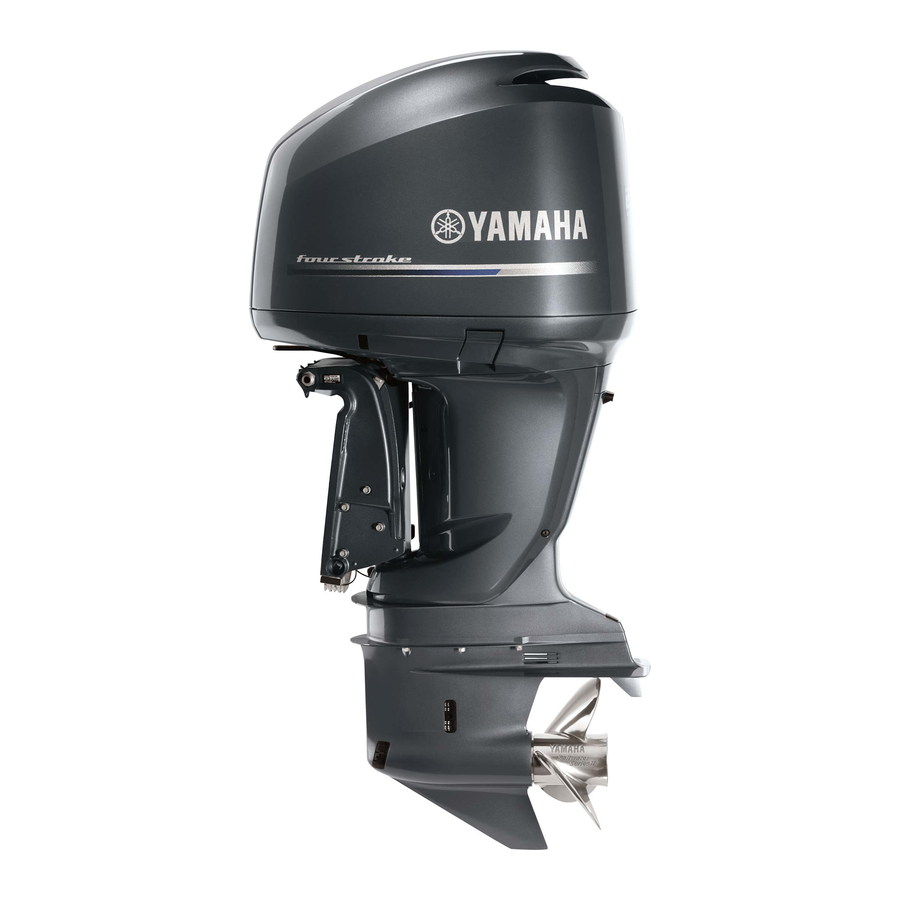
Yamaha F200A Manuals
Manuals and User Guides for Yamaha F200A. We have
3
Yamaha F200A manuals available for free PDF download: Rigging Manual, Owner's Manual, Supplementary Service Manual
Yamaha F200A Rigging Manual (329 pages)
Brand:
Yamaha
| Category:
Outboard Motor
| Size: 11.2 MB
Table of Contents
Table of Contents
5
Engine Oil Reminder Tag (4-Stroke Engines)
10
Top Cover Pictograph Description
10
Uncrating Procedure (for Typical Steel Frame)
11
Mounting the Outboard Motor
13
Water Level Guideline (4-Stroke Engines)
17
Adjusting Twin Engines
18
Max. Boat Speed Estimation
18
Mounting the Remote Oil Tank
19
Remote Oil Tank Dimensions
19
Notice for Mounting the Remote Oil Tank
19
Outboard Motor Dimensions
20
Overall Dimension Items
20
Overall Dimensions (4-Stroke)
22
Overall Dimensions (2-Stroke)
31
Clamp Bracket Dimension Items
37
Clamp Bracket Dimensions
38
Propellers
65
Propeller Specifications
66
Propeller Types
66
Propeller Identification
69
2014 Propeller Applications
70
Standard Propeller
70
STANDARD PROPELLERS (Shift Dampener System [SDS])
76
Dual Thrust Propellers
77
Weedless Propellers
78
Reliance Series Propellers (Std)
78
RELIANCE SERIES PROPELLERS (Shift Dampener System [SDS])
79
Saltwater Series Propellers
80
Saltwater Series II Propellers (Std)
81
SALTWATER SERIES II PROPELLERS (Shift Dampener System [SDS])
82
Saltwater Series Hs4 Propellers (Std)
83
SALTWATER SERIES HS4 PROPELLERS (Shift Dampener System [SDS])
83
SALTWATER SERIES XL PROPELLERS (Shift Dampener System [SDS])
84
SALTWATER SERIES XL4 PROPELLERS (Shift Dampener System [SDS])
84
Vmax Series Propellers
85
Performance Series Propellers
85
High Performance Series Propellers
86
Propeller Selection
70
Wot Operation Range Table
87
Remote Controls
89
Remote Control Types and Applications
90
Remote Switch Types and Applications
106
Remote Control Cables
121
Remote Control Attachment Kit
123
Steering Hook
127
Steering Guide Attachment Kit
130
Tie-Bar Kit
132
Conventional Wire Harness
133
Digital Electronic Remote Control Wire Harness
134
Tiller Handles
139
6X4 Multi-Function Tiller Handle
140
Multi-Function Tiller Handle Kit (for Us)
140
Tiller Handle Kit Contents
141
Wiring Diagram (for Us)
149
Exploded Diagram (for Us)
150
Multi-Function Tiller Handle Kit (for Japan)
151
Wiring Diagram (for Japan)
153
Exploded Diagram (for Japan)
154
Multi-Function Tiller Handle Contents (for Others)
155
Tiller Handle Grommet Description
155
Multi-Function Tiller Handle Kit (for Eu & Anz)
156
Handle Immobilizer Kit Contents
160
Wiring Diagram (for Eu & Anz)
161
Steering Friction Contents
162
Conventional Gauge (6Y5 & 6Y7)
165
Mounting the Meters
168
Meter Mounting Procedure
168
Analog Gauge Illumination (6Y7 Type)
168
Analog Tachometer
169
Analog Tachometer Applications
169
Analog Tachometer Dimensions
170
Pole Number Set up
170
Digital Tachometer
171
Digital Tachometer Applications
171
Digital Tachometer Dimensions
171
Pole Number Set up
172
Speedometer
173
Speedometer Types and Applications
173
Speedometer Dimensions
174
Water Pressure Damper (Op)
174
Speedometer Tube Routing
175
Digital Speedometer Set up
175
Fuel Management Gauge
176
Fuel Management Gauge Types and Applications
176
Fuel Management Gauge Dimensions
177
Fuel Sensor Installation
178
Wiring Description
179
Fuel Management Gauge Set up
181
Fuel Mgt Gauge with Speedometer Set up
181
Analog Trim Meter
182
Analog Trim Meter Applications
182
Analog Trim Meter Dimensions
182
Trim Sensor Adjustment
182
Coolant Pressure Meter
183
Coolant Pressure Meter Applications
183
Coolant Pressure Meter Dimensions
183
Coolant Press. Attachment Installation
183
Coolant Temp. Meter
184
Coolant Temp. Meter Types and Applications
184
Coolant Temp. Meter Dimensions
184
Coolant Press. Attachment And/Or Coolant Temp
185
Routing Coolant Temp. Lead
186
Routing the Coolant Press. Tube
186
Coolant Temp. Sensor And/Or Coolant Press
187
(For 4-Stroke Models)
187
Routing the Coolant Temp. Lead & Coolant Press. Tube
189
Sensor/Attachment Installation and Routing
190
Hour Meter
191
Hour Meter Applications
191
Hour Meter Dimensions
191
Wiring the Mechanical Hour Meter
192
Wiring the Digital Hour Meter
192
Voltage Meter
193
Voltage Meter Types and Applications
193
Voltage Meter Dimensions
193
Wiring the Voltage Meter
193
Fuel Meter
194
Fuel Meter Types and Applications
194
Fuel Meter Dimensions
194
Wiring the Fuel Meter
194
Charge Warning Unit
195
Charge Warning Unit Types and Applications
195
Wiring the Charge Warning Unit
195
Wire Harnesses
196
Remote-Oil Tank Harness
196
Additional Accessory Lead
196
Meter Harness
197
Trim Meter Lead
198
Trim and Oil Lead
198
Combination Trim and Oil Lead
198
Conversion Harness 1
199
Fuel Management Gauge Harness
199
Lighting Coil Extension Harness
199
Rectifier Kit
199
Wiring Diagrams
200
Wire Color Code
200
Digital Meter (6Y5)
201
Analog Meter (6Y7)
206
INTERCHANGEABILITY between TACHOMETER and ENGINE (up to 2006 and after 2007)
208
Rigging Grommet Description
211
Digital Network Gauge (6Y8)
215
Digital Network Gauge Compatible Models
216
Digital Network Gauge Application
216
Square Style Gauge Application
216
Digital Network Gauge Dimensions
217
Round Style Gauge Application
217
Square Style Gauge Dimensions
217
Round Style Gauge Dimensions
218
Optional Equipment
219
Multi-Sensor Application
219
Fitting Plate
219
Speed Sensor Kit
220
Coolant Pressure Sensor Kit
220
Speed/Coolant Pressure Sensors Kit
221
Wire Harness
222
Main Bus Wire
222
Pigtail Bus Wire
222
System Power Supply Wire
222
Immobilizer Power Distribution Wire 1
222
Network Hub
223
Fuel Tank / Gps Wire
223
Optional Equipment
224
Nmea2000 Gateway
224
Analog Gauge Interface (If)
224
Immobilizer Unit
225
Network Wiring Diagrams
226
FUEL INJECTED F30-F250 [Mechanical RC] & HPDI ENGINES
226
Initial Gauge Setup
230
Setting for Gauge When 6Y9 Multi-Sensor Is Connected
230
Troubleshooting
231
Nmea0183 Compatible Equipment Connection
232
Basic Requirements
232
Digital Network Gauge (6Y8) Function Table
233
Digital Network Premium Gauge (6Y9)
234
Digital Network Premium Gauge Compatible Models
236
Digital Network Premium Gauge Application
236
Digital Network Premium Gauge Dimensions
237
Premium Color Gauge Dimensions
237
Optional Equipment
238
Transom Multi-Sensor (6Y9)
238
Immobilizer Unit
238
Nmea2000 Gateway
239
Analog Gauge Interface (If)
239
Speed Sensor Kit
240
Coolant Pressure Sensor Kit
240
Network Hub
241
Wire Harness
242
Main Bus Wire
242
Pigtail Bus Wire
242
Gps Wire
242
Tank Wire
242
System Power Supply Wire
243
System Power Distribution Wire
243
Conversion Harness
244
Conversion Harness 1
244
Conversion Harness 4
244
Conversion Harness L
245
Twinning Harness
245
Conversion Harness M (for 2Nd Helm)
245
Conversion Harness N (for 2Nd Helm)
245
Conversion Harness P (for 2Nd Helm)
246
Conversion Harness K (for Dual Station)
246
Network Wiring Diagrams
247
SINGLE STATION W/ 6Y9 GAUGE SINGLE ENGINE APPLICATION (6X6 Binnacle Mount Digital Electronic Control)
247
SINGLE STATION W/ 6Y8 GAUGE SINGLE ENGINE APPLICATION (6X6 Binnacle Mount Digital Electronic Control)
249
SINGLE STATION W/ 6Y9 GAUGE SINGLE ENGINE APPLICATION (6X7 Concealed Digital Electronic Control)
251
SINGLE STATION W/ 6Y8 GAUGE SINGLE ENGINE APPLICATION (6X7 Concealed Digital Electronic Control)
253
Single Station W/ 6Y9 Gauge Twin Engine Application
255
Single Station W/ 6Y8 Gauge Twin Engine Application
257
Single Station W/ 6Y9 Gauge Triple Engine Application
259
Single Station W/ 6Y8 Gauge Triple Engine Application
261
Single Station W/ 6Y9 Gauge Quad Engine Application (for F/Lf225Ca, F/Lf250Ca, F/Lf300Ca, F/Lf350Ca/B)
263
Dual Station W/ 6Y9 Gauge Single Engine Application
267
Dual Station W/ 6Y8 Gauge Single Engine Application
269
Dual Station W/ 6Y9 Gauge Twin Engine Application
271
Dual Station W/ 6Y8 Gauge Twin Engine Application
273
Dual Station W/ 6Y9 Gauge Triple Engine Application
275
Dual Station W/ 6Y9 Gauge Quad Engine Application (for F/Lf225Ca, F/Lf250Ca, F/Lf300Ca, F/Lf350Ca/B)
277
Battery
281
Battery
282
Recommended Battery
282
Battery Cable Length
284
Battery Wiring
286
Isolator Equipped Model (above 150Ps Model)
286
Example for Battery Cable Wiring (Twin Engine Application)
287
Recommended Extension Length of Battery Cables
288
Recommended Battery Switch Capacity
292
Battery Charging Capability
292
Appendix
294
Model Name Designation
296
Global Models Identification Code
296
Us & Canada Models Identification (Code)
297
Us & Canada New Models Identification Code
297
Fuel System Vacuum Pressure Standard
298
Fuel Hose Routing Resistance Measuring Method
298
Lowest Vacuum Pressure Standard
299
Portable Fuel Tanks (Typical)
300
Fuel Pipes (Typical)
301
Primary Pump (Typical)
301
Pre-Delivery Inspection (Pdi)
302
Conventional Rigging Kit Contents
303
Digital Tachometer Kit
303
Digital Tachometer and Speedometer Kit
303
Twin-Motor Kit
304
Remote Oil Tank Kit (for 2-Stroke Engine)
305
Digital Network Gauge Rigging Kit Contents
306
Square/Round Style Gauge Rigging Kit Contents for Us and Canada
306
Square Style Gauge Rigging Kit for Europe
306
Round Style Gauge Rigging Kit for Europe
310
Square Style Gauge Rigging Kit for Anz
311
Square Style Gauge Rigging Kit for Japan
313
Round Style Gauge Rigging Kit for Japan
314
Immobilizer Rigging Kit Contents
315
Immobilizer Kit 1 (for Us, Anz, Crb)
315
Immobilizer Kit 2 (for Jpn)
315
Single Engine Gauge Kit for Immobilizer (for Eu, Anz, Jpn, Gen)
315
Twin Engine Gauge Kit for Immobilizer
316
Digital Network Premium Gauge Rigging Kit Contents
317
Twin Engine Premium Gauge Kit
318
Triple Engine Premium Gauge Kit (for Eu, Anz, Gen)
318
Main Helm Sw Panel Twin Engine Kit (for Us, Can)
318
Main Helm Sw Panel Triple Engine Kit (for Us, Can)
319
2Nd Helm Sw Panel Single Engine Kit (for Us, Can)
319
2Nd Helm Sw Panel Twin Engine Kit (for Us, Can)
319
2Nd Helm Sw Panel Triple Engine Kit (for Us, Can)
319
Other Rigging Kit Contents
320
Tilt Limit Switch Kit (for Us, Ca, Eu, Anz, Rus, Jpn)
320
Tilt Limit Switch Kit 2 (for Us, Ca, Eu, Anz, Jp, Rus, Tur)
320
Tilt Limit Switch Kit 3 (for Us, Ca, Eu, Anz, Jp, Rus, Tur)
321
Tilt Limit Switch Kit 4 (for Us, Ca, Eu, Anz, Jp, Rus, Tur)
321
Lighting Coil Kit (for Eu, Ca, Jpn)
322
2014 Year Models Manufacture Starting Serial Numbers
323
Advertisement
Yamaha F200A Owner's Manual (204 pages)
Brand:
Yamaha
| Category:
Outboard Motor
| Size: 10.09 MB
Table of Contents
Table of Contents
7
Identification Numbers Record
10
Outboard Motor Serial Number
10
Key Number
10
Labels
10
EC Label
10
Numeros D'identification
11
Safety Information
12
Informations De Securite
13
Fueling Instructions
16
Instructions Pour Le Carburant
17
Gasoline
18
Engine Oil
18
Essence
19
Battery Requirement
20
Choix De La Batterie
21
Propeller Selection
22
Choix De L'helice
23
Start-In-Gear Protection
24
Contre Le Demarrage En Prise
25
Composants De Base
27
Main Components
28
Operations of Controls and Other Functions
30
Remote Control
30
Trim Tab
42
Power Trim/Tilt Switch
44
Digital Tachometer
46
Digital Speedometer
54
Fuel Management Meter
60
Tilt Support Lever
66
Top Cowling Lock Levers
68
Flushing Device
68
Warning System
70
Overheat Warning
70
Low Oil Pressure Warning
72
Engine Trouble Warning
72
Operation
74
Installation
76
Breaking in (Running In) Engine
78
Rodage Du Moteur
79
Rodaje Del Motor
79
Pre-Operation Checks
80
Procedure Prealable
81
Checking the Engine Oil Level
82
Filling Fuel
82
Starting Engine
84
Demarrage Du Moteur
85
Arranque Del Motor
85
Procedure for Remote Control Model
86
Warming up Engine
90
Checking Points after Starting Engine
90
Mise a Temperature Du
91
Shifting
92
Forward
92
Reverse
92
Cambio De Marcha
93
Marche Avant
93
Stopping Engine
94
Arret Du Moteur
95
Parada Del Motor
95
Trimming Outboard Motor
96
Adjusting Trim Angle
98
Tilting Up/Down
102
Procedure for Tilting up
104
Procedure for Tilting down
106
Cruising in Other Conditions
108
Cruising in Salt Water
108
Entretien
111
Specifications
112
Transporting and Storing Outboard Motor
118
Trailering Outboard Motor
118
Storing Outboard Motor
118
Periodic Maintenance
128
Replacement Parts
128
Maintenance Chart
130
Greasing
133
Cleaning and Adjusting Spark Plug
134
Checking Fuel System
138
Inspecting Fuel Filter
140
Changing Engine Oil
144
Replacing Fuse
150
Checking Wiring and Connectors
152
Exhaust Leakage
152
Water Leakage
152
Engine Oil Leakage
152
Checking Power Trim and Tilt System
154
Checking Propeller
156
Changing Gear Oil
160
Inspecting and Replacing Anode(S)
162
Checking Battery
164
(For Electric Start Models)
164
Checking Bolts and Nuts
170
Cleaning Cooling-Water Passages
172
Checking Top Cowling
174
Motor Exterior
174
Coating the Boat Bottom
174
Restablecimientoen
177
Caso De Problema
177
Troubleshooting
178
Temporary Action in Emergency
190
Impact Damage
190
Running Single Engine
190
Power Trim/Tilt Will Not Operate
192
Treatment of Submerged Motor
194
Indice
197
Yamaha F200A Supplementary Service Manual (56 pages)
Brand:
Yamaha
| Category:
Outboard Motor
| Size: 0.74 MB
Table of Contents
Table of Contents
3
General Information
4
Specifications
5
How to Use this Manual
6
Manual Format
6
Symbols
7
Identification
8
Applicable Models
8
Serial Number
8
Features and Benefits
9
Electronic Control System
9
Ignition and Fuel Injection Timing
10
Technical Tips
11
Fuel Injection Control
11
Propeller Selection
12
Propeller Size
12
Selection
12
Predelivery Checks
13
Checking the Fuel System
13
Checking the Gear Oil
13
Checking the Engine Oil
13
Checking the Battery
13
Checking the Outboard Motor Mounting Height
14
Checking the Remote Control Cables
14
Checking the Steering Wheel
15
Checking the Gearshift and Throttle Operation
15
Checking the Tilt System
15
Checking the Engine Start Switch and Engine Stop Switch/Engine Shut-Off Switch
15
Checking the Cooling Water Pilot Hole
16
Test Run
16
Break-In
16
After Test Run
16
General Specifications
17
Maintenance Specifications
19
Power Unit
19
Spec
22
Lower Unit
22
Electrical
23
Dimensions
26
Tightening Torques
29
Specified Torques
29
General Torques
32
Special Service Tools
32
Maintenance Interval Chart
33
Chk
34
Adj
34
Power Trim and Tilt Unit
35
Assembling the Gear Pump
35
Elec
36
Fuel Control System
36
Checking the Fuel Injector
36
Checking the Low-Pressure Fuel Pump and High-Pressure Fuel Pump
37
Electrical Systems
36
Trbl Shtg
38
Yamaha Diagnostic System
38
Introduction
38
Getting Started
38
Troubleshooting
38
Self-Diagnosis
47
Diagnosing the Electronic Control System
47
Index
49
Wiring Diagram
52
Advertisement
Advertisement
Related Products
Yamaha F200AET
Yamaha F200D
Yamaha F200
Yamaha F200BET
Yamaha F200CET
Yamaha F200GET
Yamaha F200DET
Yamaha F200G1
Yamaha F200 2015
YAMAHA F200C
Yamaha Categories
Motorcycle
Musical Instrument
Electronic Keyboard
Receiver
Amplifier
More Yamaha Manuals
Login
Sign In
OR
Sign in with Facebook
Sign in with Google
Upload manual
Upload from disk
Upload from URL