Xantrex XTR6-110, XTR8-100, XTR12-70, Manuals
Manuals and User Guides for Xantrex XTR6-110, XTR8-100, XTR12-70,. We have 3 Xantrex XTR6-110, XTR8-100, XTR12-70, manuals available for free PDF download: Operating Manual

Xantrex XTR6-110, XTR8-100, XTR12-70, Operating Manual (274 pages)
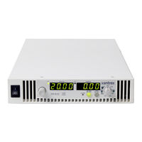
XTR 850 Watt and 1700 Watt Series Programmable DC Power Supply
Brand: Xantrex
|
Category: Power Supply
|
Size: 3 MB
Table of Contents
-
-
-
-
Introduction50
-
-
-
-
Introduction94
-
-
-
-
-
Introduction124
-
-
-
Data Format139
-
End of Message139
-
Hyperterminal139
-
-
Status Byte148
-
-
-
-
-
Introduction190
-
-
-
Gain Calibration193
-
-
-
Gain Calibration194
-
-
-
-
User Diagnostics206
-
Advertisement
Xantrex XTR6-110, XTR8-100, XTR12-70, Operating Manual (286 pages)
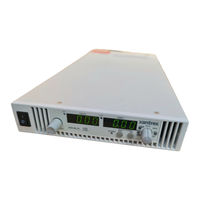
XTR 850 Watt Series Programmable DC Power Supply
Brand: Xantrex
|
Category: Power Supply
|
Size: 3 MB
Table of Contents
-
-
Front Panel26
-
-
-
Introduction46
-
-
-
-
Introduction94
-
-
-
-
-
Introduction128
-
-
-
Data Format143
-
End of Message143
-
Hyperterminal143
-
Table A-3 Table148
-
-
Status Byte154
-
-
-
Xantrex XTR6-110, XTR8-100, XTR12-70, Operating Manual (286 pages)
XTR 850 Watt Series Programmable DC Power Supply
Brand: Xantrex
|
Category: Power Supply
|
Size: 1 MB
Table of Contents
-
Figures
19-
-
Front Panel26
-
-
-
Introduction46
-
-
-
-
Introduction94
-
-
-
-
-
Introduction128
-
-
Table A-1 Table148
-
-
Status Byte154
-
Reset Command178
-
Save and Recall195
-
-
-
Introduction200
-
-
-
Gain Calibration204
-
-
-
Gain Calibration205
-
-
-
-
User Diagnostics225
-
-
-
Error Messages263
-
Error Messages264
-
-
-
Query Error List268
-
-
Advertisement
Advertisement