Sign In
Upload
Manuals
Brands
Woodward Manuals
Controller
VS-I
Woodward VS-I Manuals
Manuals and User Guides for Woodward VS-I. We have
1
Woodward VS-I manual available for free PDF download: Product Manual
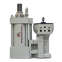
Woodward VS-I Product Manual (88 pages)
Electro-hydraulic Actuator
Brand:
Woodward
| Category:
Controller
| Size: 6 MB
Table of Contents
Table of Contents
3
Warnings and Notices
8
Electrostatic Discharge Awareness
9
Regulatory Compliance
10
Chapter 1. General Information
14
Introduction
14
VS-I Integrated and Remote Construction
16
Figure 1-1. Varistroke-I, Key Features
16
Figure 1-2. Varistroke-I Remote, Key Features
17
Figure 1-3. Hydraulic Power Cylinder - Stroke Adjustment Options
18
Figure 1-4. Application Example
19
VS-I Remote Servo Only Construction
20
Figure 1-5. Varistroke-I Remote Servo, Key Features
21
Figure 1-6. Nomenclature and Ordering Number Encoder
22
Chapter 2. Specifications
23
Physical and Performance Specifications
23
Figure 2-1. VSI Maximum Transient Flow Rates (During Full Slew)
26
Special Ambient Temperature Specifications / Allowances
27
Figure 2-2. Steady State Flow Rate
27
Performance Index
28
Diagrams
29
Figure 2-3. Performance Chart for 4", 5", and 6" Bore Actuators
29
Figure 2-4. Basic Device Block Diagram Without Trip Function
29
Figure 2-5. VS-I Integrated Hydraulic Schematic
30
Figure 2-6. VS-I Remote Hydraulic Schematic
30
Figure 2-7. VS-I Remote Servo Hydraulic Schematic
31
Figure 2-8. VS-I Spring Assist Integrated Hydraulic Schematic
31
Figure 2-9. VS-I Spring Assist Remote Hydraulic Schematic
32
Chapter 3. Installation
35
Receiving Instructions
35
Unpacking Instructions
35
Installation Instructions
36
Figure 3-1A. VS-I Integrated Product Installation Interface - Bolting Pattern and Installation Features
36
Figure 3-1B. VS-I Integrated Product Installation Interface - Bolting Pattern and Installation Features
37
Figure 3-2A. VS-I Remote. Product Installation Interface - Bolting Pattern and Installation Features
38
Figure 3-2B. VS-I Remote. Product Installation Interface-Bolting Pattern and Installation Features
39
Figure 3-2C. Hydraulic Rod Position for Different Cylinders Versions
40
Figure 3-3. VS-I Remote Servo. Product Installation Interface - Bolting Pattern
41
Figure 3-4. VS-I Lifting Positions
42
Figure 3-5. Incorrect Lifting Method
43
Figure 3-6. Suggested Configuration
45
Figure 3-7. Electrical Wiring Diagram
47
Figure 3-8. Power Supply Input Connections
48
Figure 3-9. Correct Wiring to Power Supply Input
49
Figure 3-10. Example of Incorrect Wiring to Power Supply Input
49
Figure 3-11. Recommended Wiring Strain Relief
50
Figure 3-12. Analog Input Connections
51
Figure 3-13. Final Cylinder Position Feedback Analog Input Connections
52
Figure 3-14. Cylinder Position Sensor Wiring Diagram When Using Vs-1 Internal Power
52
Figure 3-15. Cylinder Position Sensor Wiring Diagram When Using External Power Supply
53
Figure 3-16. Example of Incorrect Cylinder Position Sensor Connection When Using External Power
53
Figure 3-17. Cylinder Position Connectors
53
Figure 3-18. Cylinder Position Sensor Connection Scheme with MTS Sensor
53
Figure 3-19. Analog Output Connection
54
Figure 3-20. Discrete Inputs Connections
55
Figure 3-21. Discrete Output Connections
56
Figure 3-22. CAN Ports Connections
57
Chapter 4. Service Tool Installation
59
System Requirements
59
Setup
59
Installing the Varistroke-I Service Tool
60
Figure 4-1. Service Port Connections
60
Figure 4-2. Service Tool Welcome Screen
61
Figure 4-3. End-User License Agreement Screen
61
Figure 4-4. Service Tool Installation Screen
62
Figure 4-5. Service Tool Installation Progress Screen
62
Figure 4-6. Installation Complete and Finish Screen
63
Connecting to the Varistroke-I
64
Figure 4-7. VS 1 Service Tool Home Screen
64
Chapter 5. Calibration and Monitoring
65
Introduction
65
System Information
65
Figure 5-1. System Information and Status Overview Scree
65
System Information Page
67
Figure 5-2. System Information Page
67
Configuration and Calibration
68
Figure 5-3. Configuration/Calibration Page
68
Cylinder Configuration
69
Figure 5-4. Service Tool Calibration Screen
71
Figure 5-5. Calibration Find Minimum Stop Screen
72
Figure 5-6. Calibration in Progress Screen
73
Figure 5-7. Calibration Complete Screen
74
Manual Operation
75
Figure 5-8. Manual Operation Screen
75
Chapter 6. Configuration
76
Input Configuration
76
Figure 6-1. Input Configuration Screen
76
Output Configuration
78
Figure 6-2. Output Configuration Screen
78
Advanced Configuration
80
Figure 6-3. Advanced Configuration Screen
80
Linearization
81
Alarms/Shutdown
81
Figure 6-4. Linearization Screen
81
Figure 6-5. Alarms and Shutdowns Screen
82
Figure 6-6. Alarms and Shutdowns Configuration Screen
83
Saving and Loading Settings
84
Figure 6-7. Settings Menu
84
Chapter 7. Repair and Troubleshooting
85
General
85
Shaft Seal Replacement
85
Figure 7-1. Shaft Seals Replacement Kits and Installation
86
Servo Valve / Hydraulic Cylinder Replacement
87
Troubleshooting
87
Advertisement
Advertisement
Related Products
Woodward VariStroke-I
Woodward Vertex-Pro
Woodward Vertex
Woodward VariStroke-DX
Woodward 2301A
Woodward 2301D
Woodward 2301D-EC
Woodward 2301E
Woodward 3151A
Woodward 3161 Governor
Woodward Categories
Controller
Control Unit
Relays
Control Systems
Industrial Equipment
More Woodward Manuals
Login
Sign In
OR
Sign in with Facebook
Sign in with Google
Upload manual
Upload from disk
Upload from URL