Sign In
Upload
Manuals
Brands
Woodward Manuals
Control Unit
Vertex
User Manuals: Woodward Vertex Compressor Controller
Manuals and User Guides for Woodward Vertex Compressor Controller. We have
1
Woodward Vertex Compressor Controller manual available for free PDF download: Product Manual
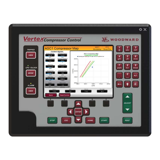
Woodward Vertex Product Manual (267 pages)
Digital Control for performance and Compressor Control
Brand:
Woodward
| Category:
Control Unit
| Size: 8 MB
Table of Contents
Table of Contents
3
Warnings and Notices
8
Electrostatic Discharge Awareness
10
Regulatory Compliance
11
Abbreviations
14
Chapter 1. General Information
15
Introduction
15
Part Number Options
15
Figure 1-1. Vertex Compressor Control (with Display)
15
General Installation and Operating Notes and Warnings
16
Figure 1-2. Vertex Compressor Control (Without Display)
16
Controller Overview
17
Figure 1-1. Typical One Section Compressor Application
18
Figure 1-2. Typical Two Section Compressor Application
18
Figure 1-3. Load Sharing Compressor Application
19
Figure 1-4. Overview of ASC Functionality Notes
20
Figure 1-5. Overview of ASC Functional Block Diagram
21
Figure 1-6. Overview of Performance Control Block Diagram
22
Figure 1-7. Overview of Load Share Control Block Diagram
22
Vertex Inputs and Outputs
24
Optional Distributed I/O
29
Keypad and Display
30
Figure 1-9. Vertex Keypad and Display
30
Watchdog Timer/Cpu Fault Control
32
Chapter 2. Installation
33
Introduction
33
Shipping Carton
33
General Installation
33
General Wiring Guidance
34
Chapter 3. Hardware Specifications
36
Vertex Description and Features
36
Figure 3-1. Functional Block Diagram (Vertex Control)
36
Environmental Specifications
37
Maintenance Info and Recommendations
37
Electromagnetic Compatibility (EMC)
38
Outline Drawing for Installation
38
Figure 3-2. Vertex Outline Drawing
39
Figure 3-3. Vertex Outline Drawing
41
Input Power Specification
42
Visual Indicators (Led's) & CPU Configuration
43
Communications (Ethernet)
43
Table 3-5 Ethernet Ports #1-4 (10/100)
44
Communications (CAN)
45
Table 3-8. Belden YR58684, Bulk Cable (Woodward PN 2008-1512)
46
Communications (RS-232/RS-485)
47
Figure 3-3. COM1 Example RS-485 Wiring
47
Communications (Service Ports)
48
Hardware - Terminal Blocks & Wiring
48
Figure 3-5. CPU Service Port (3 Pin, 2 MM)
48
Figure 3-3. Vertex Back Cover Label
48
Figure 3-4. Vertex Back Cover Label
49
Figure 3-5. Vertex Terminal Block Connectors
50
Hardware - Speed Sensor Inputs
51
Hardware - Analog Inputs (4-20 Ma)
52
Figure 3-6. Speed Sensor Block Diagram
52
Hardware - Analog Outputs (4-20 Ma)
53
Figure 3-7. Analog Input - Self-Powered Block Diagram
53
Figure 3-8. Analog Input - Loop-Powered Block Diagram
53
Hardware - Actuator Outputs
54
Figure 3-9. Analog Output Block Diagram
54
Hardware - Discrete Inputs
55
Figure 3-10. Actuator Output Block Diagram
55
Figure 3-11. Discrete Input Block Diagram
55
Hardware - Relay Outputs
56
Figure 3-12. Relay Output Block Diagram
56
Troubleshooting Fault Codes
57
Troubleshooting & Commissioning Checks
57
Chapter 4. Manual Network Setup
61
Factory Set IP Addresses for the Control
61
Factory Set Network Passwords
61
Network Setup Instructions for the Control
62
Figure 4-1. Network Setup Flowchart
62
Figure 4-2. Network Cable Connections
64
Chapter 5. Distributed I/O Expansion
65
Network Wiring Considerations
65
Figure 5-1. Daisy Chain Network (Preferred)
65
Figure 5-2. Trunk and Daisy Chain Network
65
Table 5-1. Useful Woodward Part Numbers at the Time of Writing
66
Chapter 6. Control Description
67
Introduction
67
Anti-Surge Control
68
Figure 6-1. Typical Compressor Application
68
Anti-Surge Control 2
69
Figure 6-2. Surge Cycle
69
Figure 6-3. Stonewall
70
Figure 6-4. Standard Compressor Map
71
Figure 6-6. Process Control Diagram
72
Figure 6-9. Compressor Map S_PV Regions
74
Figure 6-9. Mode Select
75
Figure 6-10. Manual Setting of Anti-Surge Valve
76
Figure 6-11. On-Line Detection
77
Figure 6-12. Anti-Surge Functions
79
Figure 6-13. Surge Detection and Counter
80
Figure 6-14. Surge Recovery and Surge Minimum Position (SMP)
81
Figure 6-15. Anti-Surge Valve Response to a Surge
82
Figure 6-16. Boost
83
Figure 6-17. Compressor Map Margin and Region
83
Figure 6-18. Anti-Surge PID
84
Figure 6-19. Rate Controller PID
85
Figure 6-20. Automatic Gain Compensation
86
Figure 6-21. Anti-Surge Decoupling
87
Figure 6-22. Effect of Valve Layout on Adjacent Stage Decoupling Amounts
88
Figure 6-23. Pressure Override Control
90
Figure 6-24. Auxiliary Control Variables
91
Figure 6-25. Analog 4-20 Ma Input Signal Filtering and Failure Monitoring
92
Figure 6-26. Valve Position Freeze Routine
93
Figure 6-27. Valve Overstroke
94
Figure 6-28. Valve Dither
94
Figure 6-29. Valve Characterization
95
Figure 6-30. Boost Response with Pre-Pack
96
Figure 6-31. Gas Properties Calculations
97
Figure 6-32. Input Signal Configure and Failure Response
98
Table 6-2. Temperature Fallback Strategy
99
Table 6-4. Suction Pressure Fallback Strategy
100
Table 6-7. Typical Discharge Coefficients
103
Figure 6-33. Two Section Compressor with One ASV
107
Commands
108
Train Commands
108
Performance Control
109
Figure 6-34. Performance Control Overview
109
Figure 6-36. Mode Select
111
Figure 6-37. Performance PID Overview
112
Figure 6-38. Limiter 1 PID Overview
115
Figure 6-39. Limiter 2 PID Overview
117
Load Sharing Control
119
Figure 6-40. Load Sharing Functional Block Overview
119
Figure 6-41. Two Compressors Supplied by a Common Suction Header
120
Figure 6-42. Load Share (LS) Implementation
121
Figure 6-43. Load Share Communication Overview
126
Figure 6-44. Load Share Communication Status
127
Chapter 7. Configuration Procedures
128
Program Architecture
128
Display Modes and User Levels
128
Configuring the Vertex
129
Figure 7-1. Initial HOME Screen (Unit Not Configured)
129
Figure 7-2. Configuration Menu - Configuration Mode (Edit)
131
Table 7-3. Configure Menu Descriptions
132
Exiting the Configure Mode
169
Table 7-4. Configuration Error Messages
170
Calibration/Stroking Procedure
176
Chapter 8. Vertex Operation
178
Software Architecture
178
Figure 8-1. Software Architecture
178
Power-Up Screen
179
Figure 8-2. Vertex Splash Screen
179
Control Mode Architecture
180
Figure 8-3. Boot-Up to HOME Screen
180
User Login Levels
181
Figure 8-4. Control Mode Architecture
181
Figure 8-5. Mode Screen
181
Navigation
182
Figure 8-6. Navigation Cross
182
Page Organization
183
Figure 8-7. Service Menu Showing "Compressor 1 Control" IN-Focus
183
Figure 8-8. Configuration Menu - Operation Mode (View Only)
184
Figure 8-9. Configuration Menu - Configuration Mode (Edit)
184
Figure 8-10. Overview Screen
185
Figure 8-11. ASC Control Popup
186
Figure 8-12. ASC Demands Screen
186
Figure 8-13. ASC Demands Screen
187
Figure 8-14. ASC Compressor Map Screen
188
Figure 8-15. ASC Control Dynamics Screen
189
Figure 8-16. Performance Control Screen
190
Figure 8-17. Performance Sequencing Screen
191
Figure 8-18. Performance Valve Demand Screen
192
Figure 8-19. Controllers Screen
193
Figure 8-20. Analog Input Summary Screen
194
Figure 8-21. Contact Input Summary Screen
195
Figure 8-22. Analog Output Summary Screen
196
Figure 8-23. Relay Output Summary Screen
197
Stop Key
198
Alarm Summary
198
Figure 8-24. Actuator Driver Summary Screen
198
Figure 8-25. ALARM Screen
199
Shutdown Summary
205
Figure 8-26. Shutdown Summary Screen
206
Manual Dynamic Adjustments of Anti-Surge, Performance, Limiter 1, Limiter 2, Load Sharing, and Pressure Override PID Controls
207
Figure 8-27. ASC Dynamics Adjustment Screen
208
Chapter 9. Communications
210
Modbus Communications
210
Figure 9-1. ASCII/RTU Representation of Three
211
Figure 9-2. Modbus Frame Definition
212
Port Adjustments
213
Vertex Control Modbus Addresses
213
Table 9-6. Boolean Write Addresses
214
Table 9-7. Boolean Read Addresses
217
Table 9-8. Analog Read Addresses
230
Table 9-9. Analog Write Addresses
238
Chapter 10. Product Support and Service Options
240
Product Support Options
240
Product Service Options
240
Returning Equipment for Repair
241
Replacement Parts
242
Engineering Services
242
Contacting Woodward's Support Organization
242
Technical Assistance
243
Appendix A. Vertex Configuration Mode Worksheets
244
Revision History
264
Declarations
265
Advertisement
Advertisement
Related Products
Woodward Vertex-Pro
Woodward VariStroke-I
Woodward VariStroke-DX
Woodward VS-I
Woodward 2300E
Woodward 26283
Woodward 3103
Woodward 505XT
Woodward 5448-880
Woodward 5448-881
Woodward Categories
Controller
Control Unit
Relays
Control Systems
Industrial Equipment
More Woodward Manuals
Login
Sign In
OR
Sign in with Facebook
Sign in with Google
Upload manual
Upload from disk
Upload from URL